Previous Year Paper

UPPSC AE Mechanical 2013 Official Paper I (Previous Year Paper)

Held in 2013

100 questions120 minutes
With answers
Free

Paper last updated:

Practise under exam conditions

Take this paper as a timed mock test. Review your answers after you submit.

Attempt timed test

Questions & answers

Read the paper at your pace. Open an explanation when you need it.

Mechanical Engineering (100 questions)

Question 1

3-2-1 principle is related with

  1. AOption (a)

    design of locating devices

  2. BOption (b)

    tool design

  3. COption (c)

    plant layout design

  4. DOption (d)

    work sampling

View answer & explanation

Correct answer

Answer: (a)A.

design of locating devices

Why this answer is correct

3-2-1 Principle :

  • There are 12 degree of freedom of a work piece i.e., movement about negative and positive axis and clockwise and anti-clockwise rotation about the three axis.
  • By providing three pins in the base, five degree of freedom will be arrested i.e. movement about negative Z-axis and the clockwise and anti-clockwise rotation about X and Y axis.
  • These three pins also ensure that machining always takes place on single plane perpendicular to the base, long the length direction.
  • This arrests movement of work piece along negative Y-direction in clockwise and anti-clock wise rotation about Z-axis.
  • A sixth pin is provided on a plane perpendicular to the previous two planes, which also arrests movement about negative X-axis.
  • By providing six pins, nine degree of freedom is arrested. Two more Degree of freedom will be arrested by providing clamping elements and from 12th direction, tool comes for machining. A smaller size of pin is called button and are used in walls.
  • Hence we can see that this principle helps us in locating the devices.
Question 2

Which of the following non-conventional machining methods does not cause tool wear?

  1. AOption (a)

    USM

  2. BOption (b)

    ECM

  3. COption (c)

    EDM

  4. DOption (d)

    Anode mechanical machining

View answer & explanation

Correct answer

Answer: (b)B.

ECM

Why this answer is correct

Explanation:

In ECM, there is no mechanical contact between the workpiece and the cutting tool and hence there is no possibility of tool wear. The material from the workpiece is removed by the chemical action of the electrolyte using Faraday’s law of electrolysis. Workpiece forms electrode (anode) and the cutting tool negative electrode (cathode).

The tool material used in ECM should have following property

  • It should have high electrical conductivity
  • It should be easily machinable and it should have high stiffness
  • Its corrosion resistance should be high.
<br>

The advantages of ECM include

  • Complex shapes can be made accurately
  • The surface finish is good due to atomic level dissolution
  • Tool wear practically absent
  • Its material removal rate is highest.

Question 3

In a blanking operation, the clearance is provided on

  1. AOption (a)

    the die

  2. BOption (b)

    both the die and the punch equally

  3. COption (c)

    the punch

  4. DOption (d)

    neither the punch nor the die

View answer & explanation

Correct answer

Answer: (c)C.

the punch

Why this answer is correct

Concept:

  • Punching or blanking is a process in which the punch removes a portion of material from the larger piece or a strip of sheet metal.
  • If the small removed piece is discarded, the operation is called punching, whereas if the small removed piece is the useful part and the rest is scrap, the operation is called blanking.

Blanking operation: 

  • Die size = blank size
  • As the Blank is fixed since the blank here is a useful part. The clearance will be provided on the punch in the blanking operation.
  • Punch size = blank size – 2 x clearance.

Piercing/Punching operation:

  • Punch size = hole size
  • As the Hole size is here is a useful part. The clearance will be provided on the die in the punching operation.
  • Die size = blank size + 2 x clearance.

Question 4

The relationship between blank diameter 'D' and the cup diameter 'd' during deep drawing process is given as

  1. AOption (a)

    D=d2+4hdD = \sqrt {{d^2} + 4hd}

  2. BOption (b)

    D=d2+2hdD = \sqrt {{d^2} + 2hd}

  3. COption (c)

    D=d2+dhD = \sqrt {{d^2} + dh}

  4. DOption (d)

    D=d2+0.5dhD = \sqrt {{d^2} + 0.5dh}

View answer & explanation

Correct answer

Answer: (a)A.

D=d2+4hdD = \sqrt {{d^2} + 4hd}

Why this answer is correct

Concept:

The relationship between blank diameter 'D' and the cup diameter 'd' during the deep drawing process is given as 

D=d2+4hdD = \sqrt {{d^2} + 4hd}

where

D = blank diameter

d = cup diameter

Additional Information

What is Deep drawing?

  • Cup drawing or deep drawing is one of the widely used sheets metal forming operations.
  • Cup-shaped objects, utensils, pressure vessels, gas cylinders, cans, shells, kitchen sink sets are some of the products of deep drawing.
  • In this process, a sheet metal called blank is placed on a die cavity, held in position using a holding plate or holding ring, and pressed against the die cavity using a solid punch.
  • The sheet metal attains the shape of the die cavity with a flat bottom.

Question 5

When a hole of diameter 'd' is punched in a metal of thickness 't', then the force required to punch a hole is equal to:

  1. AOption (a)

    dtτu

  2. BOption (b)

    πdtτu

  3. COption (c)

    πdt

  4. DOption (d)

    π4d2tτu\frac{\pi }{4}{d^2}t\tau_u

View answer & explanation

Correct answer

Answer: (b)B.

πdtτu

Why this answer is correct

Concept:

In punching and blanking, the shearing action on the sheet takes place which will depend on the shear strength of the metal.

Punching force F = Lt τ

Where L is Length of the periphery, t = thickness, τ = Ultimate shear strength

For circular section L = πd

∴ F = πdtτ

Question 6

In a tool life test, doubling the cutting speed reduces the tool life to 1/8th of the original value. Taylor’s tool life index is

  1. AOption (a)

    1

  2. BOption (b)

    1/2

  3. COption (c)

    1/3

  4. DOption (d)

    1/4

View answer & explanation

Correct answer

Answer: (c)C.

1/3

Why this answer is correct

Concept:

Taylor's tool life equation is:

V1T1n=C{V_1}T_1^n = C

Calculation:

Given:

V2 = 2V1, T2 = T1/8

V1T1n=C{V_1}T_1^n = C

V1T1n=V2T2n{V_1}T_1^n = {V_2}T_2^n

V1T1n=2V1(T18)n{V_1}T_1^n = {2V_1}\left(\frac{T_1}{8}\right)^n

T1n=2(T1n23n)T_1^n = {2}\left(\frac{T_1^n}{2^{3n}}\right)

23n = 2

3n = 1

∴ n = 1/3

Question 7

If r = chip thickness ratio, α = rake angle, then shear angle ϕ is expressed as

  1. AOption (a)

    tan⁡−1(rcos⁡α1−rsin⁡α){\tan ^{ - 1}}\left( {\frac{{r\cos\alpha }}{{1 - r\sin\alpha }}} \right)

  2. BOption (b)

    cot⁡−1(rcos⁡α1−rsin⁡α){\cot ^{ - 1}}\left( {\frac{{r\cos\alpha }}{{1 - r\sin\alpha }}} \right)

  3. COption (c)

    sin⁡−1(rcos⁡α1−rsin⁡α){\sin ^{ - 1}}\left( {\frac{{r\cos\alpha }}{{1 - r\sin\alpha }}} \right)

  4. DOption (d)

    cos⁡−1(rcos⁡α1−rsin⁡α){\cos ^{ - 1}}\left( {\frac{{r\cos\alpha }}{{1 - r\sin\alpha }}} \right)

View answer & explanation

Correct answer

Answer: (a)A.

tan⁡−1(rcos⁡α1−rsin⁡α){\tan ^{ - 1}}\left( {\frac{{r\cos\alpha }}{{1 - r\sin\alpha }}} \right)

Why this answer is correct

In machining process,

Chip thickness ratio (r) = uncut;chip;thickness(t1)chip;thickness(t2)\frac{{uncut;chip;thickness\left( {{t_1}} \right)}}{{chip;thickness\left( {{t_2}} \right)}}

r=t1t2=sin⁡ϕcos⁡(ϕ−α)r = \frac{{{t_1}}}{{{t_2}}} = \frac{{\sin \phi }}{{\cos \left( {\phi - \alpha } \right)}}

where, φ = shear angle, α = rake angle

the uncut chip thickness value is less than the chip thickness value thus chip thickness ratio is less than 1.

then tan⁡ϕ=rcosα1−rsin;α\tan \phi = \frac{{{\bf{rcos}}\alpha }}{{1 - rsin;\alpha }}

ϕ=tan⁡−1(rcos⁡;α1−rsin⁡;α)\phi = {\tan ^{ - 1}}\left( {\frac{{r\cos;\alpha }}{{1 - r\sin;\alpha }}} \right)

Question 8

In Electro Discharge Machining better surface finish is obtained at

  1. AOption (a)

    low frequency and low discharge current

  2. BOption (b)

    low frequency and high discharge current

  3. COption (c)

    high frequency and low discharge current

  4. DOption (d)

    high frequency and high discharge current

View answer & explanation

Correct answer

Answer: (c)C.

high frequency and low discharge current

Why this answer is correct

Electrical discharge machining (EDM) is a manufacturing process whereby a desired shape is obtained by using electrical discharges (sparks). Material is removed from the work-piece by a series of rapidly recurring current discharges between two electrodes, separated by a dielectric liquid and subject to an electric voltage.

EDM has the lowest specific power requirement and can achieve sufficient accuracy.

  • The accuracy and surface finish which are dependent on the overcut produced can be easily controlled by varying the frequency and current. The overcut is increased by increasing current and by decreasing frequency.
  • For optimum metal removal and better surface finish, high frequency and minimum possible current is used.
  • For roughing operation, low frequency and high current are used and for finishing application, high frequency and low current settings are used.

Question 9

Which of the following statements is incorrect about the continuous chip?

  1. AOption (a)

    It is formed while machining ductile materials at high cutting speeds.

  2. BOption (b)

    It is formed when feed and depth of cut are low

  3. COption (c)

    It results in good surface finish

  4. DOption (d)

    None of the above

View answer & explanation

Correct answer

Answer: (d)D.

None of the above

Why this answer is correct

Concept:

Machining of metals and formation of chips

Types of chip:

  1. Discontinuous chips – Formed during machining of brittle materials and while machining ductile materials at low speed.

Favourable conditions for this are:

  1. Brittle workpiece
  2. Slow speed of cutting
  3. Small rake angle
  4. Large depth of cut
  5. Continuous chips – formed during machining of ductile materials at high speed. Favourable conditions for this type of chip to be formed are as follows:
  6. Ductile material
  7. Large rake angle
  8. High cutting speed
  9. Low depth of cut
  10. Proper use of coolant and lubricant

Benefits of continuous chips are:

  • Gives high surface finish
  • High tool life
  • Low power consumption
  1. Continuous chips with built up edges – These type of chips are formed during the machining of ductile materials at medium cutting speed. Favorable conditions for this are:
  2. Ductile material
  3. High friction at face of tool
  4. Lack of coolant and lubricant

Question 10

Consider the following work piece materials:

i) Carbides

ii) Glass

iii) Copper

iv) Ceramics

Which of the above materials are best suited for ultrasonic Machining?

  1. AOption (a)

    (ii) Only

  2. BOption (b)

    (ii) and (iii)

  3. COption (c)

    (i), (ii) and (iv)

  4. DOption (d)

    (ii), (iii) and (iv)

View answer & explanation

Correct answer

Answer: (c)C.

(i), (ii) and (iv)

Why this answer is correct

During ultrasonic machining, the metal removal is achieved by hammering action of abrasive particles.

In ultrasonic machining, a tool of the desired shape vibrates at an ultrasonic frequency (19 ∼ 25 kHz) with an amplitude of around 15 – 50 μm over the workpiece.

Generally, the tool is pressed downward with a feed force, F.

Between the tool and workpiece, the machining zone is flooded with hard abrasive particles generally in the form of a water-based slurry.

As the tool vibrates over the workpiece, the abrasive particles act as the indenters and indent both the work material and the tool.

The abrasive particles, as they indent the work material, would remove the work material, particularly if the work material is brittle (due to crack initiation, propagation and brittle fracture of the material).

Applications of USM

  • USM process is used in machining hard and brittle metallic alloys, semiconductors, glass, ceramics, carbides etc
  • In machining of advanced ceramics for applications in auto-engine components
  • In machining, wire drawing, punching or blanking of small dies

Question 11

To prolong the life of shaper tools, after they are ground, they should be undergone through the following operation

  1. AOption (a)

    sand blasting

  2. BOption (b)

    shot peening

  3. COption (c)

    lapping

  4. DOption (d)

    hardening

View answer & explanation

Correct answer

Answer: (c)C.

lapping

Why this answer is correct

Concept:

Lapping:

  • It is a surface finish process that improves the surface finish of components which have been previously grounded or fine turned.
  • In this process, two surfaces are rubbed together with some abrasion in between them, by hand movement or by machine.
  • This lapping can traditionally take different forms such as: Grinding etc.

Hardening:

  • Hardening is a heat treatment process in which steel is heated to 30 – 50° above the critical range.
  • Soaking time is allowed to enable the steel to obtain a uniform temperature throughout its cross-section. Then the steel is rapidly cooled through a cooling medium. Hardening increase the brittleness in the metal.

Shot peening:

  • Shot peening is a process specifically designed to enhance the fatigue strength of components which are subjected to high alternating stress.
  • In shot peening, small spherical shots bombards the surface of the part to be finished.

Sand Blasting:

  • Sandblasting is also known as abrasive blasting. Basically, it is the operation of forcibly propelling a stream of abrasive material against a surface.
  • The sandblasting operation is done under high pressure to smooth a rough surface, roughen a smooth/Shape the surface to remove its contaminants.

Question 12

An Operating Characteristics curve (OC-curve) is a plot between

  1. AOption (a)

    consumer’s risk and producer’s risk

  2. BOption (b)

    probability of acceptance and probability of rejection

  3. COption (c)

    percentage of defective and probability of acceptance

  4. DOption (d)

    average outgoing quality and probability of acceptance

View answer & explanation

Correct answer

Answer: (c)C.

percentage of defective and probability of acceptance

Why this answer is correct

Concept:

OC curve:

  • An operating characteristic curve is a plot between probability of acceptance versus percentage of defective items (or lots).
  • Percentage of defective items is a measure of probability of rejection.

Question 13

An X̅ chart uses the following data

  1. AOption (a)

    count data

  2. BOption (b)

    attribute measurement data

  3. COption (c)

    variable measurement data

  4. DOption (d)

    None of the above

View answer & explanation

Correct answer

Answer: (c)C.

variable measurement data

Why this answer is correct

In a weaving operation, the parameter to be controlled is the number of defects per 10 square yards of material. Control chart appropriate for this task is C chart.

Explanation:

Control charts are statistical tool, showing whether a process is in control or not.

Two types of process data:

  • Variable is a continuous data, things we can measure; Example includes length, weight, time, temperature, diameter, etc.
  • Attribute is a discrete data, things we count; Examples include number or percent defective items in a lot, number of defects per item etc.
<br>

Types of Control Charts:

Variable charts are meant for variable type of data. X bar and R Chart, X bar and sigma chart, chart for the individual units

Attribute charts are meant for attribute type of data. p chart, np chart, c chart, u chart, U chart

Control charts for the variable type of data (X bar and R charts)

  • In the x bar chart, the sample means are plotted in order to control the mean value of a variable
  • In R chart, the sample ranges are plotted in order to control the variability of a variable

Control charts for Attribute type data (p, c, u charts)

  • p-charts calculates the percent defective in sample; p-charts are used when observations can be placed in two categories such as yes or no, good or bad, pass or fail etc.
  • c-charts counts the number of defects in an item; c-charts are used only when the number of occurrences per unit of measure can be counted such as number of scratches, cracks etc.
  • u-chart counts the number of defects per sample; The u chart is used when it is not possible to have a sample size of a fixed size

Question 14

Which of these would not be a reason for using acceptance sampling?

  1. AOption (a)

    a very high inspection cost

  2. BOption (b)

    boredom and fatigue

  3. COption (c)

    a process needing statistical control

  4. DOption (d)

    destructive testing

View answer & explanation

Correct answer

Answer: (b)B.

boredom and fatigue

Why this answer is correct

Concept:

Acceptance sampling is used in:

  1. Destructive testing
  2. When inspection cost is extremely high and it is technologically not feasible
  3. A statistical quality control to decide to decide whether to accept or reject a lot.

Question 15

For a M/M/I/∞/∞/FCFS queue model, the mean arrival rate is equal to 10 per hour and the mean service rate is 15 per hour. The expected queue length is

  1. AOption (a)

    1.33

  2. BOption (b)

    1.53

  3. COption (c)

    2.75

  4. DOption (d)

    3.20

View answer & explanation

Correct answer

Answer: (a)A.

1.33

Why this answer is correct

Concept:

Queuing Theory

Given:

Mean arrival rate (λ) = 10/hr, Mean service rate (μ) = 15/hr

∴ Traffic intensity, ρ=λμ=23\rho = \frac{\lambda }{\mu } = \frac{2}{3}

Queue length = ρ21−ρ\frac{{{\rho ^2}}}{{1 - \rho }}

Calculation:

Queue length = 4/91/3\frac{{4/9}}{{1/3}} = 4/3

∴ Queue length = 1.33

Question 16

ABC analysis, as an input, requires

  1. AOption (a)

    Annual usage and cost of the items

  2. BOption (b)

    Cost and criticality of the items

  3. COption (c)

    Criticality and availability of the items

  4. DOption (d)

    Availability and annual usage of items

View answer & explanation

Correct answer

Answer: (a)A.

Annual usage and cost of the items

Why this answer is correct

The inventory comprises of a large number of items. All items are not of equal importance. The firm, therefore, should pay more attention and care to those whose items whose usage value is high and fewer values to those whose usage value is low.

ABC analysis is also known as Always Better Control analysis. This is also known as the principal of the Law of Vital Few and Trivial Many.

Annual Usage Value = Annual Usage rate × Unit Cost

There are different types of selective inventory control:

ABC analysis(Always Better Control)Inventory items are classified based on their annual usage value in monetary terms.Class A - item: 10 % of the item accounts 75% costs. Class B - item: 20% of the item accounts 15% costs. Class C - item: 70% of the item accounts 10% costs.
VED Analysis (Vital, Essential, Desirable)Inventory items are classified on the basis of their criticality i.e. according to the cost of incurring a stock outV-Vital: Without which the production process would come to standstill E-Essential: Their non-availability will adversely affect the efficiency of the production system. It should be given second priority. D-Desirable: Without which the process is unaffected but is good if they are available for better efficiency.
SDE Analysis (Scarce, Difficult, Easily Available)This type of analysis is useful in the study of those items which are scarce in availabilityS-Scarce: Imported items which are generally in short supply D-Difficult: These are available in market but not always traceable or immediately supplied E-Easily: Easily available in the market
HML Analysis (High, Medium, Low Cost)This type of analysis is similar to ABC analysis, except that cost per item is taken.H-Highest: Items whose unit cost is very high, or maximum are given top priority M-Medium: Items whose unit cost is of medium value L-Low: Items whose unit cost is low
FSND Analysis (Fast, Slow, Non-moving, Dead items)Inventory items are classified in the descending order of their usage (Consumption rate/ movement value).F-Fast moving items: That are consumed in short span of time N-Normal moving items: That are consumed over a period of one year S-Slow moving items: These items are not frequently issued and consumed over a period of two years or more. D-Dead items: Consumption of such items are almost nil. It can also be taken as obsolete items

Question 17

The finite production rate inventory model relaxes which of the following EOQ assumptions?

  1. AOption (a)

    instantaneous replenishment

  2. BOption (b)

    constant lead time

  3. COption (c)

    fixed deterministic demand

  4. DOption (d)

    no variation in unit time

View answer & explanation

Correct answer

Answer: (a)A.

instantaneous replenishment

Why this answer is correct

Concept:

Based on assumptions of Economic order quantity (EOQ) model:

  • Lead time = 0
  • Constant rate of usage
  • Fixed price of material
  • Holding cold per unit component/item per unit time is fixed
  • Demand is deterministic in nature

Question 18

In a time study the observed time is 0.75 min, performance rating factor is 110% and allowances are 20% of the normal time. The standard time is

  1. AOption (a)

    0.82 min

  2. BOption (b)

    0.975 min

  3. COption (c)

    0.99 min

  4. DOption (d)

    1.03 min

View answer & explanation

Correct answer

Answer: (c)C.

0.99 min

Why this answer is correct

Concept:

Normal time = Rating;factor(%)100\frac{{{\rm{Rating;factor}}\left( {\rm{\% }} \right)}}{{100}} × observed time

Standard time = normal time × (1+allowance(%)100)\left( {1 + \frac{{{\rm{allowance}}\left( {\rm{\% }} \right)}}{{100}}} \right)

Calculation:

Normal time = 0.75 × (110/100)

∴ Normal time = 0.825 min

Standard time = 0.825 × (1 + 0.2)

∴ Standard time = 0.99 minutes

Question 19

Value engineering is used in

  1. AOption (a)

    understanding customer’s requirements

  2. BOption (b)

    designing products according to the customer’s requirements

  3. COption (c)

    producing products according to the customer’s requirements

  4. DOption (d)

    providing products to customer with enhanced functionality at no additional cost.

View answer & explanation

Correct answer

Answer: (d)D.

providing products to customer with enhanced functionality at no additional cost.

Why this answer is correct

Concept:

Value engineering or value analysis is a management technique. It seeks the best functional balance between cost, reliability, performance of a product, project, service.

  • It is a systematic approach to providing necessary functions at lowest cost
  • Promotes substitution of materials with less expensive alternatives.

Question 20

Which type of control chart should be used to directly monitor the number of defectives in a process for making iron castings?

  1. AOption (a)

    X - chart

  2. BOption (b)

    P - chart

  3. COption (c)

    C - chart

  4. DOption (d)

    R - chart

View answer & explanation

Correct answer

Answer: (c)C.

C - chart

Why this answer is correct

Control chart appropriate for this task is C chart.

Explanation:

Control charts are statistical tool, showing whether a process is in control or not.

Two types of process data:

  • Variable is a continuous data, things we can measure; Example includes length, weight, time, temperature, diameter, etc.
  • Attribute is a discrete data, things we count; Examples include number or percent defective items in a lot, number of defects per item etc.
<br>

Types of Control Charts:

Variable charts are meant for variable type of data. X bar and R Chart, X bar and sigma chart, chart for the individual units

Attribute charts are meant for attribute type of data. p chart, np chart, c chart, u chart, U chart

Control charts for the variable type of data (X bar and R charts)

  • In the x bar chart, the sample means are plotted in order to control the mean value of a variable
  • In R chart, the sample ranges are plotted in order to control the variability of a variable

Control charts for Attribute type data (p, c, u charts)

  • p-charts calculates the percent defective in sample; p-charts are used when observations can be placed in two categories such as yes or no, good or bad, pass or fail etc.
  • c-charts counts the number of defects in an item; c-charts are used only when the number of occurrences per unit of measure can be counted such as number of scratches, cracks etc.
  • u-chart counts the number of defects per sample; The u chart is used when it is not possible to have a sample size of a fixed size

Question 21

A production line is to be designed to make 2400 items/week for at least the next 3 months. The line operates 40 hours/week. The standard time required to assemble each item is 244 second. What is the smallest number of workstations required?

  1. AOption (a)

    5

  2. BOption (b)

    6

  3. COption (c)

    7

  4. DOption (d)

    8

View answer & explanation

Correct answer

Answer: (a)A.

5

Why this answer is correct

Concept:

Throughput rate/time = (Itemstime)(operating;timetime)\frac{{\left( {\frac{{Items}}{{time}}} \right)}}{{\left( {\frac{{{\rm{operating;time}}}}{{time}}} \right)}}

Cycle time = 1/Throughput rate

Machines required = Total production time/ cycle time

Calculation:

Throughput rate = 2400/40 = 60 items/hr

Cycle time = 1/60 = 1 min = 60s

Machines required = 244/60 = 4.067

∴ 5 machine are required.

Question 22

A basic feasible solution in a linear programming problem with m constraints and n variables will have

  1. AOption (a)

    at the most m variables with non zero values.

  2. BOption (b)

    at least m variables with non zero values.

  3. COption (c)

    at the most n variables with non zero values.

  4. DOption (d)

    at least n variables with non zero values.

View answer & explanation

Correct answer

Answer: (a)A.

at the most m variables with non zero values.

Why this answer is correct

The correct answer is 'at the most m variables with non zero values.'

Key Points

  • Basic Feasible Solution (BFS):
  • In a Linear Programming Problem (LPP), a basic feasible solution is obtained by setting some variables equal to zero and solving the remaining variables from the system of equations.
  • If an LPP has:
  • m constraints
  • n variables
  • Then, in a basic solution:
  • Exactly m variables can be selected as basic variables.
  • The remaining (n − m) variables are set equal to zero and are called non-basic variables.
  • Among the m basic variables, some may also become zero due to degeneracy.
  • Therefore, a basic feasible solution can have:
  • At most m variables with non-zero values.
  • Hence, the correct statement is:

“A basic feasible solution has at the most m variables with non-zero values.”

Important Points

  • A feasible solution is any solution that satisfies all constraints and non-negativity conditions.
  • A basic solution is obtained by selecting m basic variables and setting the remaining variables equal to zero.
  • A basic feasible solution is a basic solution that also satisfies all feasibility conditions.
  • If all basic variables are positive, the solution is called a non-degenerate basic feasible solution.
  • If one or more basic variables become zero, the solution is called a degenerate basic feasible solution.
  • Basic feasible solutions correspond to the corner points (extreme points) of the feasible region in linear programming.
  • The Simplex Method moves from one basic feasible solution to another in search of the optimal solution.

Question 23

The maximum value of the average outgoing quality for all possible values of proportion defective is called

  1. AOption (a)

    Average Outgoing Quality (AOQ)

  2. BOption (b)

    Acceptable Quality Level (AQL)

  3. COption (c)

    Average Outgoing Quality Limit (AOQL)

  4. DOption (d)

    Lot Tolerance Proportion Defective (LTPD)

View answer & explanation

Correct answer

Answer: (c)C.

Average Outgoing Quality Limit (AOQL)

Why this answer is correct

Concept:

Average Outgoing Quality Limit (AOQL) represents the maximum percentage defective in the outgoing product. The average out going quality depends on the incoming quality, the probability that he lot will be accepted.

  1. Incoming quality is good = outgoing quality is good
  2. Incoming quality is bad = whole lot is rejected. Therefore, outgoing quality is good since bad parts won’t get through.
  3. Incoming quality is neither very good nor very bad = outgoing quality gets worse and % defective reaches maximum known as AOQL

Question 24

20 samples of size 100 are taken. The total number of defective items is 200. What is the upper control limit of 3-sigma P-chart?

  1. AOption (a)

    0.13

  2. BOption (b)

    0.16

  3. COption (c)

    0.19

  4. DOption (d)

    None of the above

View answer & explanation

Correct answer

Answer: (c)C.

0.19

Why this answer is correct

Concept:

Pˉ=Total;number;of;defectiveTotal;number;of;observation\bar P = \frac{{Total;number;of;defective}}{{Total;number;of;observation}}

Calculation:

Pˉ=20020×100=0.1\bar P = \frac{{200}}{{20 \times 100}} = 0.1

UCL=Pˉ+z×Pˉ(1−Pˉ)n{\rm{UCL}} = \bar P + {\rm{z}} \times \sqrt {\frac{{\bar P\left( {1 - \bar P} \right)}}{n}}

UCL=0.1+30.1(0.9)100{\rm{UCL}} = 0.1 + 3\sqrt {\frac{{0.1\left( {0.9} \right)}}{{100}}}

∴ UCL = 0.19

Question 25

Which of the following is not an underlying assumption of the basic EOQ model?

  1. AOption (a)

    Stochastic demand

  2. BOption (b)

    Instant replenishment

  3. COption (c)

    Fixed lead time

  4. DOption (d)

    No shortages

View answer & explanation

Correct answer

Answer: (a)A.

Stochastic demand

Why this answer is correct

Assumption of the Basic EOQ model is:

  • Demand is known deterministic and constant
  • Cost of product is constant
  • Lead time is zero
  • Usage rate is constant
  • Inventory cost is fixed

∴ So, stochastic demand is not an underlying assumption of the basic EOQ model.

Question 26

The error estimate (e) in work sampling varies with sample size (n) as

  1. AOption (a)

    e∝1ne \propto \frac{1}{n}

  2. BOption (b)

    e∝1ne \propto \frac{1}{{\sqrt n }}

  3. COption (c)

    e∝ne \propto \sqrt n

  4. DOption (d)

    e∝1n2e \propto \frac{1}{{{n^2}}}

View answer & explanation

Correct answer

Answer: (b)B.

e∝1ne \propto \frac{1}{{\sqrt n }}

Why this answer is correct

Concept:

The general formula for the margin of error for a sample proportion is

e=Z∗ρ(1−ρ)ne = {Z^*}\sqrt {\frac{{\rho \left( {1 - \rho } \right)}}{n}}

Where, Z∗{Z^*}= value for your desired level of confidence, ρ = sample proportion, n = sample size

∴e;α1n\therefore {\bf{e}};{\bf{\alpha }}\frac{1}{{\sqrt n }}

Question 27

The producer’s risk is the probability with which a consumer will

  1. AOption (a)

    reject a bad lot

  2. BOption (b)

    reject a good lot

  3. COption (c)

    accept a good lot

  4. DOption (d)

    accept a bad lot

View answer & explanation

Correct answer

Answer: (b)B.

reject a good lot

Why this answer is correct

Concept:

  • The producer’s risk is the probability with which a consumer will reject a good lot. It is also known as Type-I error.
  • The consumer’s risk is the probability with which a consumer will accept a bad lot this is also known as Type-II error.

Question 28

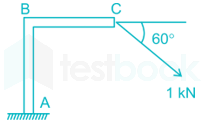
Calculate the value of thrust (in kN) at the point A for the figure shown below.

  1. AOption (a)

    0.866

  2. BOption (b)

    0.5

  3. COption (c)

    2

  4. DOption (d)

    3

View answer & explanation

Correct answer

Answer: (a)A.

0.866

Why this answer is correct

Concept:

The horizontal component of the force applied at C point causes shear stress and bending moment at point A.

The vertical component of the force applied at C point exerts thrust at point A

Calculation:

Given:

F = 1 kN

The vertical component of force is Fv = F × sin θ

Thrust at point A, Fv =  F × sin θ = 1 × sin 60° = 0.866 kN.

Question 29

The possible loading in various members framed structure are

  1. AOption (a)

    buckling or shear

  2. BOption (b)

    compression or tension

  3. COption (c)

    shear on tension

  4. DOption (d)

    bending

View answer & explanation

Correct answer

Answer: (b)B.

compression or tension

Why this answer is correct

Concept:

  • In framed structure or truss only compression or tension forces will developed.
  • In truss all joint are pin joint and load applied only at joint will be consider.

Question 30

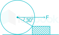
A roller of weight W is to be rolled over a wooden block as shown in the figure. The pull F required to just cause the said motion

  1. AOption (a)

    W/2

  2. BOption (b)

    W

  3. COption (c)

    3W\sqrt 3 W

  4. DOption (d)

    2W

View answer & explanation

Correct answer

Answer: (c)C.

3W\sqrt 3 W

Why this answer is correct

Concept:

Let R is the normal reaction act on roller due to block

Now,

Balancing the forces.

R cos 60° = W

R sin 60° = F

So, R = 2W

∴;F=2W×32\therefore {\rm{;F}} = 2{\rm{W}} \times \frac{{\sqrt 3 }}{2}

∴F=3W\therefore {\bf{F}} = \sqrt 3 W

Question 31

In virtual work equation some forces are neglected. Select the most appropriate answer from the following:

  1. AOption (a)

    Reaction of a rough surface on a body which rolls on it without slipping.

  2. BOption (b)

    Reaction of any smooth surface with which the body is in contact.

  3. COption (c)

    Reaction at a point or on an axis, fixed in space, around which a body is constrained to turn.

  4. DOption (d)

    All of the above

View answer & explanation

Correct answer

Answer: (d)D.

All of the above

Why this answer is correct

Concept:

  • Virtual work concept is used in the application of the principle of least action to the study of forces and movement of a mechanical system.
  • In virtual work equation reaction due to rough surface on a body which rolls on it without slipping or smooth surface with which body is in contact and reaction at a point or on an axis, fixed in space, around which a body is constrained to turn are neglected.

Question 32

A circular disc rolls down without slipping on an inclined plane. The ratio of its rotational kinetic energy to the total kinetic energy is

  1. AOption (a)

    1/4

  2. BOption (b)

    1/2

  3. COption (c)

    1/3

  4. DOption (d)

    2/3

View answer & explanation

Correct answer

Answer: (c)C.

1/3

Why this answer is correct

Concept:

Rotational kinetic energy KER=12Iω2{\rm{KE_R}} = \frac{1}{2}I{\omega ^2}

KER=12MR22ω2{\rm{K}}{{\rm{E}}_{\rm{R}}} = \frac{1}{2}\frac{{M{R^2}}}{2}{\omega ^2}

∴ Rotational kinetic energy (KER)=14Mv2\left( {{\rm{K}}{{\rm{E}}_{\rm{R}}}} \right) = \frac{1}{4}M{v^2} (∵ v = Rω)

Translational Kinetic energy KET = 12Mv2\frac{1}{2}M{v^2}

Total kinetic energy = KER + KET

Total kinetic energy = 34Mv2\frac{3}{4}M{v^2}

Calculation:

Given:

∴Rotational;kinetic;energyTotal;Kinetic;energy=14Mv2;;34Mv2\therefore \frac{{{\rm{Rotational;kinetic;energy}}}}{{{\rm{Total;Kinetic;energy}}}} = \frac{{\frac{1}{4}M{v^2}{\rm{;;}}}}{{\frac{3}{4}M{v^2}}}

∴Rotational;kinetic;energyTotal;Kinetic;energy=13\therefore \frac{{{\rm{Rotational;kinetic;energy}}}}{{{\rm{Total;Kinetic;energy}}}} = \frac{1}{3}

Question 33

Two masses 2 kg and 8 kg are moving with equal kinetic energy. The ratio of magnitude of their momentum is

  1. AOption (a)

    0.25

  2. BOption (b)

    0.50

  3. COption (c)

    0.625

  4. DOption (d)

    1.00

View answer & explanation

Correct answer

Answer: (b)B.

0.50

Why this answer is correct

Concept:

When two masses are moving with equal kinetic energy, we can find the ratio of their momentum by using the relation between kinetic energy and momentum.

Kinetic energy (KE) is given by:

KE=12mv2 KE = \frac{1}{2}mv^2

Momentum (p) is given by:

p=mv p = mv

Calculation:

Let the velocities of the 2 kg and 8 kg masses be v1v1

and v2v2

respectively.

Since the kinetic energies are equal:

12×2×v12=12×8×v22\frac{1}{2} \times 2 \times v_1^2 = \frac{1}{2} \times 8 \times v_2^2

Simplifying, we get:

2v12=8v222v_1^2 = 8v_2^2

v12=4v22v_1^2 = 4v_2^2

v1=2v2v_1 = 2v_2

Now, we find the momentum of each mass:

Momentum of the 2 kg mass, p1=2×v1p_1 = 2 \times v_1

Momentum of the 8 kg mass, p2=8×v2p_2 = 8 \times v_2

Substitute v1=2v2v1=2v2

into the equation for p1p1

:

p1=2×2v2=4v2p_1 = 2 \times 2v_2 = 4v_2

p2=8×v2p_2 = 8 \times v_2

Now, find the ratio of their momenta:

p1p2=4v28v2=48=12\frac{p_1}{p_2} = \frac{4v_2}{8v_2} = \frac{4}{8} = \frac{1}{2}

p1p2=0.50 \frac{p_1}{p_2} = 0.50

Thus, the ratio of the magnitude of their momenta is:

  1. 0.50

Question 34

The efficiency of a screw jack is maximum, when

Where α = Helix angle and ϕ = Angle of friction.

  1. AOption (a)

    α=45∘+ϕ2\alpha = 45^\circ + \frac{\phi }{2}

  2. BOption (b)

    α=45∘−ϕ2\alpha = 45^\circ- \frac{\phi }{2}

  3. COption (c)

    α = 90° + ϕ

  4. DOption (d)

    α = 90° - ϕ

View answer & explanation

Correct answer

Answer: (b)B.

α=45∘−ϕ2\alpha = 45^\circ- \frac{\phi }{2}

Why this answer is correct

Concept:

The maximum efficiency of screw jack is when helix angle α is

α=45∘−ϕ2\alpha = 45^\circ- \frac{\phi }{2}

Note:

If the friction angle is greater than the helix angle, the torque required to lower the load will positive, indicating that an effort is applied to lower the load. Such a screw is known as a self-locking screw.

Additional Information

Screw jack

  • A screw jack is a portable device consisting of a screw mechanism used to raise or lower the load. There are two types of jack Hydraulic and mechanical
  • A Hydraulic jack consists of a cylinder and piston mechanism. The movement of piston rod is used to raise or lower the load.
  • Mechanical jack can be either hand operated or power driven

The maximum efficiency of screw jack is:

η=1−sinϕ1+sinϕ\eta = \frac{{1 - sin\phi }}{{1 + sin\phi }}

Question 35

When two bodies collide without the presence of any other force or force fields?

  1. AOption (a)

    Their total kinetic energy must be conserved

  2. BOption (b)

    Their total momentum must be conserved

  3. COption (c)

    Their collision must be direct

  4. DOption (d)

    Both 1) and 2)

View answer & explanation

Correct answer

Answer: (b)B.

Their total momentum must be conserved

Why this answer is correct

Concept:

It follows the law of conservation of momentum.

The following is observed after the collision:

When two bodies collide without the presence of any other force or force fields:

  • Their total momentum must be conserved

Question 36

The tension in the cable supporting a lift is more when the lift is ________.

  1. AOption (a)

    moving downwards with uniform velocity

  2. BOption (b)

    moving upwards with uniform velocity

  3. COption (c)

    stationary

  4. DOption (d)

    moving upwards with acceleration

View answer & explanation

Correct answer

Answer: (d)D.

moving upwards with acceleration

Why this answer is correct

Concept:

When at rest,

T = mg

When the lift is moving downward:

R1=W−ma=W−Wga=W(1−ag){R_1} = W - ma = W - \frac{W}{g}a = W\left( {1 - \frac{a}{g}} \right)

When the lift is moving upward:

R1=W+ma=W+Wga=W(1+ag){R_1} = W + ma = W + \frac{W}{g}a = W\left( {1 + \frac{a}{g}} \right)

Question 37

The angle between two forces P and Q is α. The resultant of these forces is

  1. AOption (a)

    P2+Q2+2PQsin⁡α\sqrt {{P^2} + {Q^2} + 2PQ\sin \alpha }

  2. BOption (b)

    P2+Q2+2PQcos⁡α\sqrt {{P^2} + {Q^2} + 2PQ\cos \alpha }

  3. COption (c)

    P2+Q2 \sqrt {{P^2} + {Q^2} \ }

  4. DOption (d)

    P2+Q2−2PQcos⁡α\sqrt {{P^2} + {Q^2} - 2PQ\cos \alpha }

View answer & explanation

Correct answer

Answer: (b)B.

P2+Q2+2PQcos⁡α\sqrt {{P^2} + {Q^2} + 2PQ\cos \alpha }

Why this answer is correct

Concept:

Resultant force F, of any two forces F1 and F2 with an angle θ between them can be given by vector addition as

Fr2=F12+F22+2F1F2cos⁡θF_r^2 = F_1^2 + F_2^2 + 2{F_1}{F_2}\cos \theta

Hence by comparing the options with the above equation option 2 is the correct answer.

Question 38

A fixed gear having 200 teeth is in mesh with another gear having 50 teeth. The two gears are connected by an arm. The number of turns made by the smaller gear for one revolution of arm about the center of the bigger gear is

  1. AOption (a)

    2

  2. BOption (b)

    3

  3. COption (c)

    4

  4. DOption (d)

    5

View answer & explanation

Correct answer

Answer: (d)D.

5

Why this answer is correct

Step noArmPinionGear
Fixed arm x rotate y0 0 y+ 1 + x X + y-TP/TG - x TP/TG y – x TP/TG

NG = 0,  (Given)

y−x4=0y - \frac{x}{4} = 0,

y = x/4; x=4y

for one revolution of arm: y = 1; x = 4 rev.

NP=X+y

∴ NP = 5 revolution.

Question 39

For high speed engine the cam follower should move with

  1. AOption (a)

    Uniform velocity

  2. BOption (b)

    Simple harmonic motion

  3. COption (c)

    Uniform acceleration and retardation

  4. DOption (d)

    Cycloidal motion

View answer & explanation

Correct answer

Answer: (d)D.

Cycloidal motion

Why this answer is correct

Concept:

Cycloidal motion curve has the best dynamic characteristics. The acceleration is finite at all times and the starting and ending acceleration is zero. It will yield a cam mechanism with the lowest vibration, stress, noise and shock characteristics. Hence for the high-speed engine, the cam follower should move with Cycloidal motion.

Note:

Uniform velocity motion

Uniform Acceleration and Retardation

Simple harmonic motion

Cycloidal motion

Question 40

A flywheel is fitted to the crank shaft of an engine having W amount of indicated work per revolution. Permissible limits of coefficient of fluctuation of energy and speed are CE and CS respectively. The kinetic energy of the flywheel is given by

  1. AOption (a)

    2W⋅CECS2\frac{{W \cdot {C_E}}}{{{C_S}}}

  2. BOption (b)

    W⋅CE2CS\frac{{W \cdot {C_E}}}{{{2C_S}}}

  3. COption (c)

    W⋅CECS\frac{{W \cdot {C_E}}}{{{C_S}}}

  4. DOption (d)

    W⋅Cs2CE\frac{{W \cdot {C_s}}}{{{2C_E}}}

View answer & explanation

Correct answer

Answer: (b)B.

W⋅CE2CS\frac{{W \cdot {C_E}}}{{{2C_S}}}

Why this answer is correct

Concept:

Coefficient of fluctuation of energy:

CE=Maximum;fluctuation;of;energyWork;done;per;cycle{C_E} = \frac{{Maximum;fluctuation;of;energy}}{{Work;done;per;cycle}}

CE=ΔEW⇒ΔE=CE.W{C_E} = \frac{\Delta E}{W} \Rightarrow \Delta E=C_E.W

Coefficient of fluctuation of speed:

CS=Maximum;fluctuation;of;speedMean;speed CS=ω1−ω2ω=2(ω1−ω2)(ω1+ω2)\begin{array}{l} {C_S} = \frac{{Maximum;fluctuation;of;speed}}{{Mean;speed}}\ {C_S} = \frac{{{ω _1} - {ω _2}}}{ω } = \frac{{2\left( {{ω _1} - {ω _2}} \right)}}{{\left( {{ω _1} + {ω _2}} \right)}} \end{array}

ω = mean angular speed during the cycle (rad/s)

ω=ω1+ω22ω = \frac{{{ω _1} + {ω _2}}}{2}

Maximum fluctuation of energy: ΔE = CE. W

ΔE=12Iω12−12Iω22=12I(ω1+ω2)(ω1−ω2) ΔE=Iω(ω1−ω2)=Iω2(ω1−ω2)ω=Iω2CS K.E=12Iω2=12.ΔECS=CEW2CS\begin{array}{l} {\rm{\Delta }}E = \frac{1}{2}Iω _1^2 - \frac{1}{2}Iω _2^2 = \frac{1}{2}I\left( {{ω _1} + {ω _2}} \right)\left( {{ω _1} - {ω _2}} \right)\ {\rm{\Delta }}E = Iω \left( {{ω _1} - {ω _2}} \right) = I{ω ^2}\frac{{\left( {{ω _1} - {ω _2}} \right)}}{ω } = I{ω ^2}{C_S}\ K.E = \frac{1}{2}I{ω ^2} = \frac{1}{2}.\frac{{{\rm{\Delta }}E}}{{{C_S}}} = \frac{{{C_E}W}}{{2{C_S}}} \end{array}

Question 41

If the ratio of the length of connecting rod to crank radius increases, then

  1. AOption (a)

    primary unbalanced force increases

  2. BOption (b)

    primary unbalanced force decreases

  3. COption (c)

    secondary unbalanced force increases

  4. DOption (d)

    secondary unbalanced force decreases

View answer & explanation

Correct answer

Answer: (d)D.

secondary unbalanced force decreases

Why this answer is correct

Concept:

The unbalanced force due to reciprocating masses varies in magnitude but constant in direction while due to the revolving masses, the unbalanced force is constant in magnitude but varies in direction.

Unbalanced force,

FU;=;m.ω2.r(cosθ+cos2θn);=;m.ω2.rcosθ+m.ω2.r×cos2θn;=;FP+FS{F_U}; = ;m.{\omega ^2}.r\left( {cosθ + \frac{{cos2θ }}{n}} \right); = ;m.{\omega ^2}.rcosθ + m.{\omega ^2}.r \times \frac{{cos2θ }}{n}; = ;{F_P} + {F_S}

The expression (m. ω2.r cos θ) is known as primary unbalanced force and (m.ω2.r×cos2θn)\left( {m.{\omega ^2}.r \times \frac{{cos2θ }}{n}} \right) is called secondary unbalanced force.

Unbalanced force is given by

FU=m.ω2.r.cosθ+m.ω2.r.cos2θn=FPrimary+FSecondary{F_U} = m.{\omega ^2}.r.cos\theta + m.{\omega ^2}.r.\frac{{cos2\theta }}{n} = {F_{Primary}} + {F_{Secondary}}

Where n = Ratio of length of the connecting rod to the crank radius = l / r

So secondary unbalanced force, FSecondary=m.ω2.r.cos2θn{F_{Secondary}} = m.{\omega ^2}.r.\frac{{cos2\theta }}{n} decreases when n increases.

Question 42

A system in dynamic balance implies that

  1. AOption (a)

    the system is critically damped 

  2. BOption (b)

    there is no critical speed in the system 

  3. COption (c)

    the system is also statically balanced

  4. DOption (d)

    there will be absolutely no wear of bearings

View answer & explanation

Correct answer

Answer: (c)C.

the system is also statically balanced

Why this answer is correct

Explanation:

If the rotor is statically balanced, it will not roll under the action of gravity, regardless of the angular position of the rotor. The requirement for static balance is that the centre of gravity of the system of masses is at the axis of rotation.

Static balance: ΣF = 0

A rotating system of mass is in dynamic balance when the rotation does not produce any resultant centrifugal force or couple.

Dynamic balance: ΣF = 0 and ΣM = 0

It can be said that if the rotor is dynamically balanced then it is also statically balanced. The converse is not true for all the rotors. A statically balanced rotor is not always dynamically balanced, the exception being the single plane rotors.

Question 43

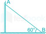
A rod AB of length 1 m is sliding as shown in the figure. At an instant when the rod makes 60° angle with the horizontal plane, the downwards velocity of point A is 1 m/s. What is the angular velocity of the rod at that instant?

  1. AOption (a)

    2.0 rad/s

  2. BOption (b)

    1.5 rad/s

  3. COption (c)

    0.5 rad/s

  4. DOption (d)

    0.75 rad/s

View answer & explanation

Correct answer

Answer: (a)A.

2.0 rad/s

Why this answer is correct

Concept:

The instantaneous center (I) is the intersection point of the normal drawn at point A and B.

So,

Angular velocity (ω) of the rod at this instant is

ω=VR=VAIA{\rm{\omega }} = \frac{V}{R} = \frac{{{V_A}}}{{IA}}

Calculation:

Given:

ω=11×cos⁡60∘{\rm{\omega }} = \frac{1}{{1 \times \cos60^\circ }}

∴ ω = 2 rad/s

Additional Information

Instantaneous Centre:

The instantaneous center of a rigid body is located by the point where the lines perpendicular to the direction of the velocity of two different points on the body meets. If two points have velocity parallel to each other then the line drawn perpendicular to those points will meet at infinity, therefore their instantaneous center will lie at infinity.

Properties of Instantaneous Centre:

  • At the instantaneous centre of rotation, one rigid link rotates instantaneously relative to another for the configuration of the mechanism considered.
  • The two rigid links have no linear velocities to each other at the instantaneous centre.
  • The two rigid links have the same linear velocity relative to the third rigid link, or any other link.


The number of Instantaneous Centres:

The number of Instantaneous centres in a mechanism is equal to the number of possible combinations of two links.

N=n(n−1)2N =\frac{{n(n-1)}}{{2}}N=n(n−1)2N=n(n−1)2N=n(n−1)2N=n(n−1)2


Where

n = number of links. 

Types of Instantaneous Centres:

  • Fixed instantaneous centres.
  • Permanent instantaneous centres.
  • Neither fixed nor a permanent instantaneous centre.

Question 44

Isochronism in a governor is desirable when

  1. AOption (a)

    the engine operates at low speeds.

  2. BOption (b)

    the engine operates at high speeds

  3. COption (c)

    only one speed is desired to be kept at all loads

  4. DOption (d)

    the engine operates at variable speeds

View answer & explanation

Correct answer

Answer: (c)C.

only one speed is desired to be kept at all loads

Why this answer is correct

Explanation:

Isochronous Governor: 

  • A governor is said to be isochronous when the equilibrium speed is constant (i.e. range of speed is zero) for all radii of rotation of the balls within the working range, neglecting friction.
  • The isochronism is the stage of infinite sensitivity.
  • A spring-loaded governor can only possibly be an Isochronous governor.

Hunting: 

  • If a governor is too sensitive, a small variation of speed causes large change in the sleeve movement. Thus, a governor is said to be hunt if the speed of the engine fluctuates continuously above and below the mean speed.

Stability: 

  • A governor is said to be stable when for each speed within the working range there is only one radius of rotation of the fly-ball at which the governor is in equilibrium.

Question 45

A rigid body can be replaced by two masses placed at fixed distance apart. The two masses form an equivalent dynamic system, if (select the most appropriate answer).

  1. AOption (a)

    the sum of the two masses is equal to the total mass of the body

  2. BOption (b)

    the centre of gravity of two masses coincide with that of the body

  3. COption (c)

    the sum of the mass moment of inertia of the masses about their centre of gravity is equal to the mass moment inertia of the body

  4. DOption (d)

    All of the above

View answer & explanation

Correct answer

Answer: (d)D.

All of the above

Why this answer is correct

Concept:

The two masses form an equivalent dynamic system if:

  1. The sum of the two masses is equal to the total mass of the body
  2. The centre of gravity of two masses coincide with that of the body
  3. The sum of the mass moment of inertia of the masses about their centre of gravity is equal to the mass moment inertia of the body

Question 46

A torsional system with discs of moment of inertia I1 and I2 are shown in figure, which are gear driven. The ratio of speed of shaft B to shaft A is G. The equivalent moment of inertia of disc on shaft B at the speed of shaft ‘A’ is equal to

  1. AOption (a)

    GI2

  2. BOption (b)

    G2I2

  3. COption (c)

    I2/G

  4. DOption (d)

    I2/G2

View answer & explanation

Correct answer

Answer: (b)B.

G2I2

Why this answer is correct

Concept:

It is given that the ratio of speed of shaft B to shaft A is G and we have to calculate the equivalent moment of inertia of disc.

So we will equate the kinetic energy of both the shafts.

Since we are having the ratio of their speeds by equating the kinetic energy we will directly get the equivalent moment of inertia of B at the speed of shaft A.

∴ According to question:

\(\frac{1}{2}{{I}_{2}}\omega {B}^{2}=\frac{1}{2}{{I}{eq}}\omega _{A}^{2}\)

\({{I}{eq}}={{(\frac{{{\omega }{B}}}{{{\omega }{A}}})}^{2}}\times {{I}{2}}\)

∴ Ieq = G2I2

Question 47

Identify lower pairs. Select the most appropriate answer.

  1. AOption (a)

    ball and socket

  2. BOption (b)

    cam and follower

  3. COption (c)

    piston and cylinder

  4. DOption (d)

    both (1) and (2)

View answer & explanation

Correct answer

Answer: (c)C.

piston and cylinder

Why this answer is correct

Explanation:

Kinematic pairs are classified under three headings namely, lower pair, higher pair and wrapping pair.

Lower Pair: 

A pair is said to be a lower pair when the connection between two elements is through the area of contact. Some of the types of Lower pair are:

  • Revolute Pair
  • Prismatic Pair
  • Screw Pair
  • Cylindrical Pair
  • Planar Pair

Higher Pair: 

A pair is said to be higher pair when the connection between two elements has only a point or line of contact. Examples of higher pairs are:

  • A point contact takes place when spheres rest on plane or curved surfaces (in case of ball bearings)
  • Contact between teeth of a skew-helical gears
  • Contact made by roller bearings
  • Contact between teeth of most of the gears
  • Contact between cam-follower
  • Spherical Pair
<br>

Wrapping Pairs:

In a higher pair, the contact between the two bodies has only a line contact or a point contact. Whereas in a wrapping pair, one body completely wraps over the other. The typical example is of a belt and a pulley or a chain and a sprocket where the belt completely wraps around the pulley or the chain completely wraps around the sp


Spherical Pair:

This pair usually look like lower pair but it is multiple point contact pair like wrapping pair which is a higher pair.

  • Example. Ball in Socket joint.

Question 48

In a spring dash pot, mass system if m = mass, k = spring stiffness and ωn = natural frequency of vibration, then critical damping is equal to

  1. AOption (a)

    2km2\sqrt {km}

  2. BOption (b)

    2 m⋅ωn

  3. COption (c)

    both 1) and 2)

  4. DOption (d)

    neither 1) nor 2)

View answer & explanation

Correct answer

Answer: (c)C.

both 1) and 2)

Why this answer is correct

Concept:

The critical damping cc is defined as the value of damping coefficient c for which the term 

(c2m)2;−;km;=;0 cc2m;=;km⇒cc;=;2mkm;=;2mωn;=;2km\begin{array}{l} {\left( {\frac{c}{{2m}}} \right)^2}; - ;\frac{k}{m}; = ;0\ \frac{{{c_c}}}{{2m}}; = ;\sqrt {\frac{k}{m}} \Rightarrow {c_c}; = ;2m\sqrt {\frac{k}{m}} ; = ;2m{\omega _n}; = ;2\sqrt {km} \end{array}

Question 49

An imaginary circle on a gear which gives a rolling action, as same as the motion as the actual gear, is called:

  1. AOption (a)

    Pitch circle

  2. BOption (b)

    Clearance circle

  3. COption (c)

    Addendum circle

  4. DOption (d)

    Dedendum circle

View answer & explanation

Correct answer

Answer: (a)A.

Pitch circle

Why this answer is correct

Pitch circle is an imaginary circle which by the pure rolling action, would give the same motion as the actual gear. The diameter of the pitch circle is known as Pitch circle diameter. The size of the gear is usually specified by the pitch circle diameter. It is also known as pitch diameter.

Addendum Circle: It is the circle drawn through the top of the teeth and is concentric with the pitch circle. It is also called the Outside circle.

Dedendum circle: It is the circle drawn through the bottom of the teeth. It is also called the root circle.

Clearance is the radial distance from the top of the tooth to the bottom of the tooth, in a meshing gear (the difference between the dedendum of one gear and the addendum of the mating gear).

Important Point:

Pitch circle diameter: It is the diameter of the pitch circle. The size of the gear is usually specified by the pitch circle diameter. It is also known as pitch diameter.

Circular pitch: It is the distance measured on the circumference of the pitch circle from a point of one tooth to the corresponding point on the next tooth. It is usually denoted by pc. Mathematically,

Circular pitch, pc=πdTp_c = \frac{{\pi d}}{T}

Diametral Pitch: It is the ratio of the number of teeth to the pitch circle diameter in millimeters. It is denoted by pd. Mathematically,

pd=Td=πpcp_d = \frac{T}{d}= \frac{\pi}{p_c}

Module (m): It is the ratio of the pitch circle diameter in millimeters to the number of teeth. It is usually denoted by m. Mathematically

m=dTm = \frac{d}{T}

Question 50

The pressure angle in a cam depends on

  1. AOption (a)

    the angle of ascent

  2. BOption (b)

    the lift of the follower

  3. COption (c)

    offset between centre lines of cam and follower

  4. DOption (d)

    All of the above

View answer & explanation

Correct answer

Answer: (d)D.

All of the above

Why this answer is correct

Concept:

  • The Pressure angle is defined as the angle between the normal to the pitch curve at a point and the direction of the follower motion.
  • Its values depends on the angle of ascent, the lift of the follower and offset between centre lines of cam and follower.
  • Pressure angle varies in magnitude at all instants of the follower motion.

Question 51

In a flat belt drive, the centrifugal tension in the belt

  1. AOption (a)

    Increases the power transmitted

  2. BOption (b)

    Decreases the power transmitted

  3. COption (c)

    Has no effect on the power transmitted

  4. DOption (d)

    increases power transmitted up to a certain speed and then decreases

View answer & explanation

Correct answer

Answer: (b)B.

Decreases the power transmitted

Why this answer is correct

Explanation:

Centrifugal effects on belts:

  • While in motion, as a belt passes over a pulley, the centrifugal effect due to its own weight tends to lift the belt from the pulley.
  • Owing to symmetry, the centrifugal force produces equal tensions on the two sides of the belt i.e. on the tight side as well as on the slack side.

The magnitude of centrifugal force is Tc = mv2

Thus, we can say that the centrifugal tension is independent of the tight and slack side tensions and depends only on the velocity of the belt over the pulley.

Total tension on tight side T ⇒ T1 + Tc

Total tension on slack side T ⇒ T2 + Tc

Considering centrifugal tension:

Friction tension on tight side = T - Tc = T1

Let T2 be the friction tension on the slack side

T1T2=eμθ=k\frac{T_1}{T_2}=e^{\mu \theta}=k or T2=T1kT_2=\frac{T_1}{k}

We know that power P = (T1 - T2)v

Putting the value of T2 in power

P=T1(1−1k)vP=T_1\left(1-\frac{1}{k}\right)v

Neglecting centrifugal tension:

Friction tension on tight side = T

Let T2' be the tension on the slack side.

T1T2′=eμθ=k\frac{T_1}{T_2^{'}}=e^{\mu \theta}=k or T2′=T1kT_2^{'}=\frac{T_1}{k}

We know that power P = (T1 - T2')v

P=T(1−1k)vP=T\left(1-\frac{1}{k}\right)v

As T1 is lesser than T, the power transmitted is less when centrifugal tension is taken into account.

Central tension (Tc) reduces the effective tension difference available for power transmission due to the impact on the belt's ability to maintain grip and avoid slippage under higher speeds. Thus, higher centrifugal forces (and hence higher (Tc)) result in reduced effective power transmission. While theoretically the gross difference (T1 - T2) remains, the real-world power transmissible is diminished due to the practical reduced (T1) and (T2) load handling resulting from (Tc). Hence, centrifugal tension in the belt ultimately decreases the power transmitted due to its effect on reducing the effective load-carrying capacity of the belt.

Mistake Points Two cases have been taken, the maximum tension in case of centrifugal tension and ignoring centrifugal tension. The tension T and T1 are different and as per the value of T and T1  we are able to say that centrifugal tension decreases power output

Question 52

If there are several unbalanced masses in a rotor in different planes, the minimum number of balancing masses required is

  1. AOption (a)

    1

  2. BOption (b)

    2

  3. COption (c)

    3

  4. DOption (d)

    4

View answer & explanation

Correct answer

Answer: (b)B.

2

Why this answer is correct

Concept:

Balancing of Several Masses Rotating in Different Planes

  • When several masses revolve in different planes, they may be transferred to a reference plane (briefly written as R.P.), which may be defined as the plane passing through a point on the axis of rotation and perpendicular to it.
  • The effect of transferring a revolving mass (in one plane) to a reference plane is to cause a force of magnitude equal to the centrifugal force of the revolving mass to act in the reference plane, together with a couple of magnitude equal to the product of the force and the distance between the plane of rotation and the reference plane.
<br>

The masses in the different plane are represented in one plane in the following way:

  • In order to have a complete balance of the several revolving masses in different planes, the following two conditions must be satisfied:
  1. The force in the difference plane must balance, i.e. the resultant force must be zero.
  2. The couples about the reference plane must balance, i.e. the resultant couple must be zero.

Hence to satisfy the above mentioned condition we need minimum two balancing masses.

Question 53

The tractive force is maximum or minimum when the angle of inclination of the crank to the line of stroke is equal to

  1. AOption (a)

    90° and 225°

  2. BOption (b)

    135° and 180°

  3. COption (c)

    180° and 225°

  4. DOption (d)

    135° and 315°

View answer & explanation

Correct answer

Answer: (d)D.

135° and 315°

Why this answer is correct

Concept:

Partial balancing of the locomotives results in the following

c is a fraction of the reciprocating parts to be balanced

Swaying couple: 

The unbalanced forces along the line of stroke for the two cylinders constitute a couple about the centre line between the cylinders. (a is distance between the center lines of the two cylinders)

FC=(1−c)mω2r×a2(cos⁡θ+sin⁡θ)F_C=(1-c)m\omega^2r\times\frac{a}{2}(\cos\theta+\sin\theta)

It is maximum or minimum when θ = 45° or θ = 225°

Fc,max=±a2(1−c)mω2rF_{c,max}=±\frac{a}{\sqrt2}(1-c)m\omega^2r

Variation in tractive force: 

A variation in the tractive force (effort) of an engine is caused by the unbalanced portion of the primary force which acts along the line of stroke of a locomotive engine.

FT=(1−c)mω2r(cos⁡θ−sin⁡θ)F_T=(1-c)m\omega^2r(\cos\theta-\sin\theta)

It is maximum or minimum when θ = 135° or θ = 315°

FT,max=±2(1−c)mω2rF_{T,max}=±\sqrt2(1-c)m\omega^2r

Hammer blow: 

The maximum magnitude of the unbalanced force along the perpendicular to the line of stroke is known as hammer blow. (Balancing mass, B at radius b)

Fb=B.ω2.bF_b=B.\omega^2.b

Question 54

The number of instantaneous centres of rotation in a quick return motion mechanism are

  1. AOption (a)

    six

  2. BOption (b)

     eight

  3. COption (c)

    twelve

  4. DOption (d)

    fifteen

View answer & explanation

Correct answer

Answer: (a)A.

six

Why this answer is correct

Concept:

The number of instantaneous centres in a considered kinematic chain is equal to the number of combinations of two links: If N is the number of instantaneous centres and n is the number of links.

N=n(n−1)2N = \frac{{n\left( {n - 1} \right)}}{2}

Crank and slotted lever quick return motion mechanism is an inversions of Single Slider Crank Chain which is a modification of the basic four-bar chain.

Calculation:

The number of instantaneous centers:

N=L(L−1)2=4(4−1)2=6N = \frac{{L\left( {L - 1} \right)}}{2} = \frac{{4\left( {4 - 1} \right)}}{2} = 6

where L is the number of links.

Question 55

In a forced vibration system, for which value of frequency ratio (ωf/ωn), the transmissibility is same for all the values of damping factors

  1. AOption (a)

    1

  2. BOption (b)

    2

  3. COption (c)

    √2

  4. DOption (d)

    1/2

View answer & explanation

Correct answer

Answer: (c)C.

√2

Why this answer is correct

Concept:

In vibration isolation system, the ratio of the force transmitted to the force applied is known as the isolation factor or transmissibility ratio.

T=FTFO=1+(2ζωωn)2[1−(ωωn)2+(2ζωωn)2]T = \frac{{{F_T}}}{{{F_O}}} = \frac{{\sqrt {1 + {{\left( {2\zeta \frac{\omega }{{{\omega _n}}}} \right)}^2}} }}{{\sqrt {\left[ {1 - {{\left( {\frac{\omega }{{{\omega _n}}}} \right)}^2} + {{\left( {2\zeta \frac{\omega }{{{\omega _n}}}} \right)}^2}} \right]} }}

  • When ω/ωn = 0 ⇒ TR = 1, (independent of ζ)
  • When ω/ωn = 1 and ξ = 0 ⇒ TR = ∞, (independent of ζ)
  • When frequency ratio ω/ωn = √2, then all the curves pass through the point TR = 1 for all values of damping factor ξ.
  • When frequency ratio ω/ωn < √2, then TR > 1 for all values of damping factor ξ. This means that the force transmitted to the foundation through elastic support is greater than the force applied.
  • When frequency ratio ω/ωn > √2, then TR < 1 for all values of damping factor ξ. This shows that the force transmitted through elastic support is less than the applied force. Thus vibration isolation is possible only in the range of ω/ωn > √2. Here the force transmitted to the foundation increases as the damping is increased.

Question 56

Constant velocity ratio between two shafts can be obtained, if they are connected by

  1. AOption (a)

    V-belts and pulleys

  2. BOption (b)

    Sprocket and chains

  3. COption (c)

    Gears

  4. DOption (d)

    Universal joint

View answer & explanation

Correct answer

Answer: (c)C.

Gears

Why this answer is correct

Concept:

Constant velocity ratio between the two shafts can be obtained if they are connected by gears.

∵ Velocity ratio = 1/ Gear ratio

Where, Gear ratio (G) = T/t, T = Number of teeth on gear and, t = Number of teeth on pinion.

Question 57

Differential gear is used in an automobile to

  1. AOption (a)

    transmit power from the engine to driving wheels.

  2. BOption (b)

    multiply the available engine torque

  3. COption (c)

    enable the vehicle to negotiate the curves properly

  4. DOption (d)

    serves all the three functions as mentioned in 1), 2) and 3) above.

View answer & explanation

Correct answer

Answer: (c)C.

enable the vehicle to negotiate the curves properly

Why this answer is correct

Concept:

Schematic Diagram of a Differential

The differential gear used in the rear-drive of an automobile. Its function is

  • (a) To rotate the rear wheels at different speeds while the automobile is taking a turn
  • (b) To transmit motion from the engine shaft to the rear driving wheels

Hence we can say that they enable the vehicle to negotiate the curves properly.

Question 58

The point of contraflexure is a point where

  1. AOption (a)

    Shear force changes sign

  2. BOption (b)

    Bending moment changes sign

  3. COption (c)

    Shear force is maximum

  4. DOption (d)

    Bending moment is maximum

View answer & explanation

Correct answer

Answer: (b)B.

Bending moment changes sign

Why this answer is correct

Explanation:

  • In a bending beam, a point of contraflexure is a location where the bending moment is zero (changes its sign). In a bending moment diagram, it is the point at which the bending moment curve intersects with the zero lines.
  • At the point of contraflexure, the bending moment is zero.

For example:

A propped cantilever beam with uniformly distributed load over the entire span

The corresponding BMD is

At distance L/4 from the left support, we get point of contraflexure, as there is the change in sign. At that point, the Bending moment is zero.

Question 59

A simply supported beam carries a load ‘P’ through a bracket as shown in figure. The maximum bending moment in the beam is

  1. AOption (a)

    Pl2P\frac{l}{2}

  2. BOption (b)

    Pl2+a⋅P2P\frac{l}{2}+\frac{a\cdot P}{2}

  3. COption (c)

    Pl4+Pa2\frac{Pl}{4}+\frac{Pa}{2}

  4. DOption (d)

    Pl2−a⋅PP\frac{l}{2}-a\cdot P

View answer & explanation

Correct answer

Answer: (c)C.

Pl4+Pa2\frac{Pl}{4}+\frac{Pa}{2}

Why this answer is correct

Concept:

By equivalent load system

Reactions at both ends:

RA=P2−PalR_A=\frac{P}{2}-\frac{Pa}{l}

RB=P2+PalR_B=\frac{P}{2}+\frac{Pa}{l}

Bending Moment:

BM at the end-point is zero. 

The bending moment is occurring at the midpoint.

Let us assume point 'C' is the midpoint of the beam.

Therefore, BM=[P2−Pal]×l2BM=[\frac{P}{2}-\frac{Pa}{l} ]\times\frac{l}{2} 

BM=[P2−Pal]×l2+PaBM={[\frac{P}{2}-\frac{Pa}{l} ]\times\frac{l}{2}}+Pa

⇒ BM=Pl4−Pa2+PaBM={\frac{Pl}{4}-\frac{Pa}{2} }+Pa

Therefore, BM=Pl4+Pa2BM={\frac{Pl}{4}+\frac{Pa}{2} }


Minimum bending moment, BMmin=Pl4−Pa2BM_{min}=\frac{Pl}{4}-\frac{Pa}{2}

∴ Maximum bending moment = BMmax=Pl4+Pa2BM_{max}=\frac{Pl}{4}+\frac{Pa}{2}

Question 60

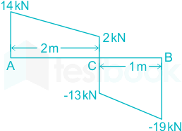
The shear-force diagram of a loaded beam is shown in the following figure. The maximum bending moment in the beam is

  1. AOption (a)

    16 kN-m

  2. BOption (b)

    11 kN-m

  3. COption (c)

    28 kN-m

  4. DOption (d)

    8 kN-m

View answer & explanation

Correct answer

Answer: (a)A.

16 kN-m

Why this answer is correct

Concept:

The area under the shear-force diagram gives a bending moment between those two points and the area under the load diagram gives shear-force between those two points. i.e.

\({{M}{B}}-{{M}{A}}=\mathop{\int }{A}^{B}{{F}{x-x}}dx\)

\({{F}{B}}-{{F}{A}}=-\mathop{\int }{A}^{B}{{w}{x-x}}dx\)

Calculation:

Given:

\({{M}{C}}-{{M}{A}}=\frac{1}{2}\times \left( 14+2 \right)\times 2\)

MC = 16 kN-m   (MA = 0)

Similarly;

∴ MB – Mc = 16 kN-m

Question 61

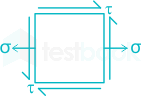
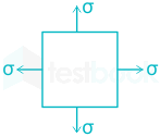
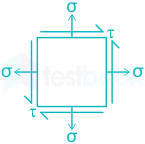
In which of the following two dimensional state of stress, Mohr’s stress circle takes the shape of a point.

  1. AOption (a)

  2. BOption (b)

  3. COption (c)

  4. DOption (d)

View answer & explanation

Correct answer

Answer: (c)C.

Why this answer is correct

Concept:

When the normal stresses on the two mutually perpendicular planes are equal and alike then the radius of the Mohr circle will be zero.

Radius;of;Mohr′s;Circle,R=(σx−σy2)2+τxy2{\rm{Radius;of;Mohr's;Circle}},R = \sqrt {{{\left( {\frac{{{\sigma _x} - {\sigma _y}}}{2}} \right)}^2} + {\tau _{xy}}^2}

Only in figure 3, we can see that 

 σx=σy;and;τxy=0{\sigma _x} = {\sigma _y};and;{\tau _{xy}} = 0

∴ option 3 is the correct answer

Question 62

If the shear force diagram for a beam is a triangle with the length of the beam as its base, the beam is

  1. AOption (a)

    a cantilever with a point load at its free end.

  2. BOption (b)

    a cantilever with uniformly distributed load over its whole span.

  3. COption (c)

    a simply supported beam with a point load at its mid-point.

  4. DOption (d)

    a simply supported beam with uniformly distributed load over its whole span.

View answer & explanation

Correct answer

Answer: (b)B.

a cantilever with uniformly distributed load over its whole span.

Why this answer is correct

Concept:

Cantilever beam carries a uniformly distributed load:

Shear force:

SFxx = Wx

Shear force diagram is a triangle with zero at the free end and WL at the fixed end.

Bending Moment:

BMxx=Wx22B{M_{xx}} = \frac{{{Wx^2}}}{2}

The bending moment at any section is proportional to the square of the distance of the section from the free end. This follows a parabolic shape.

Question 63

The torque transmitted by a solid shaft of diameter d and maximum allowable shear stress τ is

  1. AOption (a)

    π4τd3\frac{\pi }{{4}}\tau {d^3}

  2. BOption (b)

    π16τd3\frac{\pi }{{16}}\tau {d^3}

  3. COption (c)

    π32τd3\frac{\pi }{{32}}\tau {d^3}

  4. DOption (d)

    π64τd3\frac{\pi }{{64}}\tau {d^3}

View answer & explanation

Correct answer

Answer: (b)B.

π16τd3\frac{\pi }{{16}}\tau {d^3}

Why this answer is correct

Concept:

Using torsion equation:

TIP=τmaxR=GθL\frac{T}{{{I_P}}} = \frac{{{{\rm{\tau }}_{max}}}}{R} = \frac{{G\theta }}{L}

Where,

T = applied torque, IP = Polar section modulus, τmax = Maximum shear stress in the shaft material,

R = Radius of the shaft, G = Modulus of Rigidity, θ = Angle of twist, L = Length of the shaft

IP=π32D4{I_P} = \frac{\pi }{{32}}{D^4}

R = D/2

From shear stress criteria:

τmax(allowable)×2D=TIP\frac{{{{\rm{\tau }}_{{\rm{max}}\left( {allowable} \right)}} \times 2}}{D} = \frac{T}{{{I_P}}}

Substituting the values of IP{I_P}  and R we get 

Torque (T) = π16τd3\frac{\pi }{{16}}\tau {d^3}

Question 64

A thick cylinder, having ro and ri as outer and inner radii, is subjected to an internal pressure P. The maximum tangential stress at the inner surface of the cylinder is

  1. AOption (a)

    P(ro2+ri2)ro2−ri2\frac{P\left( r_{o}^{2}+r_{i}^{2} \right)}{r_{o}^{2}-r_{i}^{2}}

  2. BOption (b)

    P(ro2−ri2)ro2−ri2\frac{P\left( r_{o}^{2}-r_{i}^{2} \right)}{r_{o}^{2}-r_{i}^{2}}

  3. COption (c)

    \(\frac{2\text{Pr}{i}^{2}}{\left( r{o}^{2}-r_{i}^{2} \right)}\)

  4. DOption (d)

    P(ro2−ri2)ri2\frac{P\left( r_{o}^{2}-r_{i}^{2} \right)}{r_{i}^{2}}

View answer & explanation

Correct answer

Answer: (a)A.

P(ro2+ri2)ro2−ri2\frac{P\left( r_{o}^{2}+r_{i}^{2} \right)}{r_{o}^{2}-r_{i}^{2}}

Why this answer is correct

Concept:

According to Lame’s equation:

\({{\sigma }{r}}={{C}{1}}+\frac{{{C}_{2}}}{{{r}^{2}}}\)

\({{\sigma }{\theta }}={{C}{1}}-\frac{{{C}_{2}}}{{{r}^{2}}}\)

Where C1 and C2 are constants.

Boundary conditions for a thick cylinder:

At r = ri ; σr={{\sigma }_{r}}= -P

R = ro ; σr=0{{\sigma }_{r}}=0

So, \({{C}{1}}=\frac{Pr{i}^{2}}{r_{o}^{2}-r_{i}^{2}}\)

\(\therefore {{C}{2}}=-\frac{r{i}^{2}r_{o}^{2}P}{r_{o}^{2}-r_{i}^{2}}\)

So tangential stress σθ{{\sigma }_{\theta }} is given by

\({{\sigma }{\theta }}=\frac{Pr{i}^{2}}{r_{o}^{2}-r_{i}^{2}}+\frac{\frac{r_{i}^{2}r_{o}^{2}P}{r_{o}^{2}-r_{i}^{2}}}{{{r}^{2}}}\)

 For maximum tangential stress occur r = ri

\(\therefore {{\sigma }{\theta }}=\text{ }!!~!!\text{ }\frac{P\left( r{o}^{2}+r_{i}^{2} \right)}{r_{o}^{2}-r_{i}^{2}}\)

Question 65

A thin cylindrical shell of diameter d and thickness t is subjected to an internal pressure P. The Poisson’s ratio is v. The ratio of longitudinal strain to volumetric strain is

  1. AOption (a)

    1−v2−v\frac{{1 - v}}{{2 - v}}

  2. BOption (b)

    2−v1−v\frac{{2 - v}}{{1 - v}}

  3. COption (c)

    1−2v3−4v\frac{{1 - 2v}}{{3 - 4v}}

  4. DOption (d)

    1−2v5−4v\frac{{1 - 2v}}{{5 - 4v}}

View answer & explanation

Correct answer

Answer: (d)D.

1−2v5−4v\frac{{1 - 2v}}{{5 - 4v}}

Why this answer is correct

Concept:

Let εL and εh be the longitudinal strain and hoop strain and μ is the Poisson ratio and E is the modulus of elasticity.

Now,

Longitudinal strain:

εL=pd2tE−pd4tE×μ εL=pd2tE(1−μ2)\begin{array}{l} {\varepsilon _L} = \frac{{pd}}{{2tE}} - \frac{{pd}}{{4tE}} \times \mu \ {\varepsilon _L} = \frac{{pd}}{{2tE}}\left( {1 - \frac{\mu}{2} } \right) \end{array}

Circumferential/Hoop strain:

εh=pd2tE−pdμ4tE εh=pd2tE(1−12μ) εh=pd4tE(2−μ)\begin{array}{l} {\varepsilon _h} = \frac{{pd}}{{2tE}} - \frac{{pd\mu }}{{4tE}}\ {\varepsilon _h} = \frac{{pd}}{{2tE}}\left( {1 - \frac{1}{2}\mu } \right)\ {\varepsilon _h} = \frac{{pd}}{{4tE}}\left( {2 - \mu } \right) \end{array}

Now,

Hoop strain = change in circumference or circumferential original circumference strain.

εh=πδdπd=δdd{\varepsilon _h} = \frac{{\pi \delta d}}{{\pi d}} = \frac{{\delta d}}{d} (δd is change in diameter)

But,

δdd\frac{{\delta d}}{d} = strain of diameter

∴ change in diameter = εh × Original diameter

And also, longitudinal strain

=δℓℓ=εL= \frac{{\delta \ell }}{\ell } = {\varepsilon _L}

Now,

∴ Change in length = εℓ × Original length

Now,

Capacity of shell =V=π4×d2ℓ= V = \frac{\pi }{4} \times {d^2}\ell

∴ Change in the capacity of the shell =δV=π4d2×δℓ+π4×2d;δd;ℓ= \delta V = \frac{\pi }{4}{d^2} \times \delta \ell + \frac{\pi }{4} \times 2d;\delta d;\ell

Now,

δVV=εℓ+εh ∴δVV=δℓℓ+2δdd\begin{array}{l} \frac{{\delta V}}{V} = {\varepsilon _\ell } + {\varepsilon _h}\ ∴ \frac{{\delta V}}{V} = \frac{{\delta \ell }}{\ell } + 2\frac{{\delta d}}{d} \end{array}

∴δVV=pd2tE;(12−μ)+2pd2tE(1−12μ) ∴δVV=pd2tE[12−μ+2−μ]\begin{array}{l} ∴ \frac{{\delta V}}{V} = \frac{{pd}}{{2tE}};\left( {\frac{1}{2} - \mu } \right) + \frac{{2pd}}{{2tE}}\left( {1 - \frac{1}{2}\mu } \right)\ ∴ \frac{{\delta V}}{V} = \frac{{pd}}{{2tE}}\left[ {\frac{1}{2} - \mu + 2 - \mu } \right] \end{array}

∴δVV=pd2tE(52−2μ)∴ \frac{{\delta V}}{V} = \frac{{pd}}{{2tE}}\left( {\frac{5}{2} - 2\mu } \right)

 \(\therefore \frac{{{\epsilon }{L}}}{{{\epsilon }{V}}}=\frac{5-4\mu}{2-\mu}\)

Question 66

In a compression test the fracture in cast iron specimen would occur along,

  1. AOption (a)

    An oblique plane

  2. BOption (b)

    Along the axis of the load

  3. COption (c)

    At right angles to the specimen axis

  4. DOption (d)

    Fracture will not occur in cast iron

View answer & explanation

Correct answer

Answer: (a)A.

An oblique plane

Why this answer is correct

Concept:

  • Cast iron is very strong in compression but weak in shear.
  • When a cast iron specimen is subjected to compression test a plane inclined at 45o to the normal plane has shear stresses due to a resolved compression force.
  • Thus this plane is subjected to shear stress.
  • Therefore the fracture would be due to slip of planes and is due to the combination of compressive and shear stresses.
  • As cast iron is weak in shear, failure occurs along this inclined plane.

Question 67

The Erichsen cupping number of a metal sheet indicates its

  1. AOption (a)

    ductility

  2. BOption (b)

    hardenability

  3. COption (c)

    toughness

  4. DOption (d)

    drawing ability

View answer & explanation

Correct answer

Answer: (d)D.

drawing ability

Why this answer is correct

Concept:

  • Erichsen cupping number of a metal sheet indicates its drawing ability.
  • Erichsen cupping test is used to check the formability characteristics of composite sheet material.

Question 68

In an I-section of a beam subjected to transverse shear force, the maximum shear stress is developed at

  1. AOption (a)

    the bottom edges of the top flange.

  2. BOption (b)

    the top edges of the top flange

  3. COption (c)

    the centre of the web

  4. DOption (d)

    the upper edges of the bottom flange.

View answer & explanation

Correct answer

Answer: (c)C.

the centre of the web

Why this answer is correct

Explanation:

Shear;stress;at;any;section;is;given;by,;τ;=V×A×yˉ;I×B{\rm{Shear;stress;at;any;section;is;given;by}},;\tau ; = \frac{{V \times A \times \bar y;}}{{I \times B}}

where V = Transverse shear, A = Area above or below the section, yˉ\bar y = Distance of CG form NA, I = Moment of inertia

Shear stress distribution for I-section is:

The maximum shear stress is at the neutral axis.

Bending Stress distribution for I section:

Bending stress will be zero at the neutral axis.

Question 69

The equivalent length of a column of length L having both the end fixed is

  1. AOption (a)

    2L

  2. BOption (b)

    L

  3. COption (c)

    L/2

  4. DOption (d)

    L/√2

View answer & explanation

Correct answer

Answer: (c)C.

L/2

Why this answer is correct

Concept:

End ConditionBoth end hingedOne end fixed other freeBoth end fixedOne end fixed and other hinged
Effective length (Le)L2L1/2L2\frac{L}{{\sqrt 2 }}

Question 70

A circular shaft is subjected to a twisting moment T and bending moment M. The ratio of Maximum bending stress to Maximum shear stress is given by:

  1. AOption (a)

    2M/T

  2. BOption (b)

    M/T

  3. COption (c)

    2T/M

  4. DOption (d)

    M/2T

View answer & explanation

Correct answer

Answer: (a)A.

2M/T

Why this answer is correct

Concept:

Maximum bending stress, σb=MyI=MZ=32Mπd3{\sigma _b} = \frac{{My}}{I} = \frac{M}{Z} = \frac{{32M}}{{\pi {d^3}}}

Maximum shear stress, τ=16Tπd3\tau = \frac{{16T}}{{\pi {d^3}}}

σbτ=2MT\frac{{{\sigma _b}}}{\tau } = \frac{{2M}}{T}

Question 71

The total strain energy of a beam of length L, having moment of inertia of its section I, when subjected to a bending moment M is

  1. AOption (a)

    \({{\rm{}}_{\rm{}}} \mathop \smallint \nolimits_0^{\rm{L}} \frac{{{{\rm{2M}}^2}}}{{{\rm{EI}}}}{\rm{dx}}\)

  2. BOption (b)

    \({{\rm{}}_{\rm{}}} \mathop \smallint \nolimits_0^{\rm{L}} \frac{{{{\rm{M}}^2}}}{{{\rm{EI}}}}{\rm{dx}}\)

  3. COption (c)

    \({{\rm{}}_{\rm{}}} \mathop \smallint \nolimits_0^{\rm{L}} \frac{{{{\rm{M}}^2}}}{{2{\rm{EI}}}}{\rm{dx}}\)

  4. DOption (d)

    None of these

View answer & explanation

Correct answer

Answer: (c)C.

\({{\rm{}}_{\rm{}}} \mathop \smallint \nolimits_0^{\rm{L}} \frac{{{{\rm{M}}^2}}}{{2{\rm{EI}}}}{\rm{dx}}\)

Why this answer is correct

Concept:

The strain energy of a beam due to bending (Ub) having length L and moment of inertia of its section I, when subjected to a bending moment M is given by,

\({{\rm{U}}_{\rm{b}}} = \mathop \smallint \nolimits_0^{\rm{L}} \frac{{{{\rm{M}}^2}}}{{2{\rm{EI}}}}{\rm{dx}}\)

Related Points:

The strain energy of a beam due to axial loading (Ua) having length L and cross sectional area A, when subjected to a axial load P is given by,

\({{\rm{U}}_{\rm{a}}} = \mathop \smallint \nolimits_0^{\rm{L}} \frac{{{{\rm{P}}^2}}}{{2{\rm{EA}}}}{\rm{dx}}\)

The strain energy of a beam due to torsion (Ut) having length L and polar moment of inertia of its section J, when subjected to a torque T is given by,

\({{\rm{U}}_t} = \mathop \smallint \nolimits_0^{\rm{L}} \frac{{{{\rm{T}}^2}}}{{2{\rm{GJ}}}}{\rm{dx}}\)

Where, E is modulus of elasticity and G is modulus of rigidity.

Question 72

A cantilever beam of length L is subjected to a moment M at the free end. The moment of inertia of the beam cross-section about the neutral axis is I and the Young modulus is E. The magnitude of the maximum deflection is.

  1. AOption (a)

    ML22EI\frac{{M{L^2}}}{{2EI}}

  2. BOption (b)

    ML2EI\frac{{M{L^2}}}{{EI}}

  3. COption (c)

    2ML2EI\frac{{2M{L^2}}}{{EI}}

  4. DOption (d)

    4ML2EI\frac{{4M{L^2}}}{{EI}}

View answer & explanation

Correct answer

Answer: (a)A.

ML22EI\frac{{M{L^2}}}{{2EI}}

Why this answer is correct

Concept:

EId2ydx2=M{EI}\frac{{{d^2}y}}{{d{x^2}}} = M

Calculation:

By integrating the above equation we get,

EIdydx=Mx+C1EI\frac{{dy}}{{dx}} = Mx + {C_1}

Once again integrating, we get

EI;y=Mx22+C1x+C2EI;y = \frac{{M{x^2}}}{2} + {C_1}x + {C_2}

For cantilever beam at \(x = 0,\frac{{dy}}{{dx}} = 0;& ;x = 0,~y = 0\) (x taken from fixed-end).

From this we get C1 = C2 = 0,  Hence

y=Mx22EIy = \frac{{M{x^2}}}{{2EI}}  

Deflection will be maximum when x = L

∴ Maximum deflection is

 ymax=ML22EI{y_{max}} = \frac{{M{L^2}}}{{2EI}}

Question 73

Basic equation of deflection (y) of the beam is represented by EId2ydx2=MEI\frac{{{d^2}y}}{{d{x^2}}} = M, where EI → flexural rigidity and M → Bending moment, then EId3ydx3EI\frac{{{d^3}y}}{{d{x^3}}} will be:

  1. AOption (a)

    Rate of loading

  2. BOption (b)

    Shear force at the section

  3. COption (c)

    Bending moment at section

  4. DOption (d)

    Zero always

View answer & explanation

Correct answer

Answer: (b)B.

Shear force at the section

Why this answer is correct

Concept:

Shear force at any section of the beam is equal to the slope of the Bending Moment Diagram

S.F=(dMdx)S.F = \left( {\frac{{dM}}{{dx}}} \right)

It is given that M=EId2ydx2M = EI\frac{{{d^2}y}}{{d{x^2}}}

∴ (dMdx)=ddx(EId2ydx2)=;EId3ydx3;\left( {\frac{{dM}}{{dx}}} \right) = \frac{d}{{dx}}\left( {EI\frac{{{d^2}y}}{{d{x^2}}}} \right) = ;EI\frac{{{d^3}y}}{{d{x^3}}};

∴ EId3ydx3EI\frac{{{d^3}y}}{{d{x^3}}} represents the shear force at the section

Note that slope of Shear force diagram gives the load acting at that section

W=(dFdx)W = \left( {\frac{{dF}}{{dx}}} \right)

EId2ydx2=MEI\frac{{{d^2}y}}{{d{x^2}}} = M , in this equation, y is the deflection

Deflection y is obtained by double integration method

EId2ydx2=MEI\frac{{{d^2}y}}{{d{x^2}}} = M

EIdydx=∫M+C1EI\frac{{dy}}{{dx}} = \smallint M + {C_1}

here, dydx=slope;or;angular;deviation;of;the;axis;of;the;beam\frac{{dy}}{{dx}} = {\rm{slope;or;angular;deviation;of;the;axis;of;the;beam}}

and the constant C1 is determined by using boundary conditions for the slope.

EI.;y=∫!!!∫M+C1x+C2EI.;y = \int!!!\int M + {C_1}x + {C_2}

C2 is determined by using the boundary conditions of deflection

Question 74

Compound tubes are used in internal pressure cases, for following reasons

  1. AOption (a)

    For increasing the thickness

  2. BOption (b)

    For increasing the outer diameter of the tube

  3. COption (c)

    The strength is more

  4. DOption (d)

    It evens out stresses

View answer & explanation

Correct answer

Answer: (d)D.

It evens out stresses

Why this answer is correct

Concept:

  • When a cylinder is subjected to internal pressure, there is a significant variation in the hoop stress across the wall thickness.
  • Due to this the material of the cylinder is not being used to maximum advantage. So to obtain a more uniform hoop stress distribution compounding tubes are used.

Question 75

Normal stress on a plane, the normal to which is inclined at an angle θ with the line of action of applied uniaxial stress σ is given by

  1. AOption (a)

    σ/sin2 θ

  2. BOption (b)

    σ/cos2 θ

  3. COption (c)

    σ cos2 θ

  4. DOption (d)

    σ sin2 θ

View answer & explanation

Correct answer

Answer: (c)C.

σ cos2 θ

Why this answer is correct

Concept:

Stress developed on oblique plane:

Pn = P cosθ

Ps = P sinθ

σn=P !! !! cos !!θ!! A′{{\sigma }_{n}}=\frac{\text{P }!!~!!\text{ cos }!!\theta!!\text{ }}{{{A}'}}

σn=P !! !! cos !!θ!! Acosθ{{\sigma }_{n}}=\frac{\text{P }!!~!!\text{ cos }!!\theta!!\text{ }}{\frac{A}{cos\theta }}

∴σn=σcos2θ\therefore {{\sigma }_{n}}=\sigma co{{s}^{2}}\theta

∴ σs = σcosθsinθ

Question 76

A shaft of 20 mm diameter and length 1 m is subjected to a twisting moment, due to which shear strain on the surface of the shaft is 0.001. The angular twist in the shaft is

  1. AOption (a)

    0.10 radian

  2. BOption (b)

    0.01 radian

  3. COption (c)

    0.05 radian

  4. DOption (d)

    0.50 radian

View answer & explanation

Correct answer

Answer: (a)A.

0.10 radian

Why this answer is correct

Concept:

Torsion equation:

TJ=τr=Gθl\frac{T}{J}=\frac{\tau}{r}=\frac{G\theta}{l}

Shear strain:

ϕ=τGϕ=\frac{\tau}{G}

τG=rθl\frac{\tau}{G}=\frac{r\theta}{l}

ϕ=rθlϕ=\frac{r\theta}{l}

∴ϕ !!θ!! =rl\therefore \frac{ϕ }{\text{ }!!\theta!!\text{ }}=\frac{\text{r}}{\text{l}}

Calculation:

Given:

d = 20 mm, r = 10 mm = 0.01 m, length = 1 m, ϕ = 0.001

ϕ !!θ!! =rl\frac{ϕ }{\text{ }!!\theta!!\text{ }}=\frac{\text{r}}{\text{l}}

\(\text{ }!!\theta!!\text{ }!!!!\text{ }=\text{ }!!!!\text{ }\frac{ϕ \times \text{l}}{\text{r}}\)

∴ θ = 0.001×10.01\frac{0.001\times 1}{0.01} 

∴ θ = 0.1 radian

Question 77

A beam of uniform strength is one in which

  1. AOption (a)

    bending moment is same throughout the beam

  2. BOption (b)

    deflection is the same throughout the length

  3. COption (c)

    bending stress is same in every section along the longitudinal axis.

  4. DOption (d)

    shear stress is uniform throughout the beam

View answer & explanation

Correct answer

Answer: (c)C.

bending stress is same in every section along the longitudinal axis.

Why this answer is correct

Concept:

A beam of uniform strength is one in which Bending stress developed at every cross-section of the beam remains the same along the longitudinal axis.

There are two methods to make a beam of uniform strength:-

  • Method 1: Varying the width of the beam and keeping depth constant.
  • Method 2: Varying the depth of the beam and keeping width constant.

Question 78

Increase in ferrite phase in steel increases

  1. AOption (a)

    strength

  2. BOption (b)

    hardness

  3. COption (c)

    ductility

  4. DOption (d)

    brittleness

View answer & explanation

Correct answer

Answer: (c)C.

ductility

Why this answer is correct

  • Due to increase in ferrite phase in steel ductility of the steel increases

  • Due to cohesion between molecules the body resist the force. This resistance offered by the body is known as strength of material.

Mechanical properties of a metal:

DuctilityA metal is said to be ductile when it can be drawn out into wires under tension without rupture. Wire drawing depends upon the ductility of a metal. A ductile metal must be both strong and plastic. Copper and aluminum are good examples of ductile metals.
MalleabilityMalleability is that property of a metal by which it can Be extended in any direction by hammering, rolling etc. without causing rupture. Lead is an example of a malleable metal.
HardnessHardness is a measure of a metals ability to withstand scratching, wear, and abrasion, indentation by harder bodies.
BrittlenessBrittleness is that property of a metal which permits no permanent distortion before breaking. Cast iron is an example of a brittle metal which will break rather than bend under shock or impact.
ToughnessToughness is the property of a metal to withstand shock or impact. Toughness is the property opposite to brittleness. Wrought iron is an example of tough metal.
TenacityThe tenacity of a metal is its ability to resist the effect of tensile forces without rupturing. Mild steel, Wrought Iron and copper are some examples of tenacious metals.
ElasticityElasticity of a metal is its power of returning to its original shape after the applied force is released. Properly heat treated spring is a good example for elasticity.
ResistivityIt is the property of a substance due to which it opposes the flow of the electric current.

Question 79

Co-ordination number of FCC crystal is

  1. AOption (a)

    4

  2. BOption (b)

    8

  3. COption (c)

    12

  4. DOption (d)

    16

View answer & explanation

Correct answer

Answer: (c)C.

12

Why this answer is correct

Explanation:

In the FCC unit cell effective number of atoms = 8 corner atoms x (1/8) (each atom is shared by 8-unit cells) + 6 faces cantered atoms x (1/2) (each shared by two-unit cells) = 4

Unit CellCoordination No.No. of Atoms Per Unit CellAtomic packing factor
Simple Unit Cell6152%
Body-centred Cubic8268%
Face-centred Cubic12474%
Hexagonal Closest Packed12674%


Diagram
Effective no. of lattice points⇒18×8=1\Rightarrow \frac{1}{8} \times 8 = 118×8+1=2\frac{1}{8} \times 8 + 1 = 218×8+12×6=4\frac{1}{8} \times 8 + \frac{1}{2} \times 6 = 4


Slip systems: The combination of a slip plane and its direction of slip is known as a slip system. Each pattern of atomic arrangements results in a different number of slip systems.

  • For the BCC crystal structure: 48
  • For FCC crystal structure: 12
  • For Hexagonal close packed structure: 3

Additional InformationCo-ordination Number: 

  • The coordination number of an atom is the number of atoms it is touching in a unit cell.

Question 80

Which of the following elements determine maximum attainable hardness in the steel?

  1. Chromium
  2. Manganese
  3. Carbon
  4. Molybdenum

Select the correct answer using codes given below:

  1. AOption (a)

    1 only

  2. BOption (b)

    1 and 2

  3. COption (c)

    3 only

  4. DOption (d)

    2 and 4

View answer & explanation

Correct answer

Answer: (c)C.

3 only

Why this answer is correct

Concept:

  • Maximum attainable surface hardness depends primarily on carbon content.
  • Maximum hardness and strength in small sections increases as carbon content increases, up to 0.7%.
  • Alloying elements primarily influence hardenability. They also influence other mechanical and fabrication properties including toughness and machinability.

Question 81

How many space lattices does the Bravais lattices consist of?

  1. AOption (a)

    3

  2. BOption (b)

    7

  3. COption (c)

    9

  4. DOption (d)

    14

View answer & explanation

Correct answer

Answer: (d)D.

14

Why this answer is correct

Concept:

There are 14 possible Bravais lattices in three-dimensional space.

These 14 Bravais lattices are grouped into seven lattice system:

Triclinic, Monoclinic, Orthorhombic, Tetragonal, Rhombohedral, Hexagonal, and Cubic.

Following are the crystal system and their relationship:

Crystal SystemAxial RelationshipsInter axial Angles
Cubica = b = cα = β = γ = 90°
Hexagonala = b ≠ cα = β = 90°, γ = 120°
Tetragonala = b ≠ cα = β = γ = 90°
Rhombohedral (Trigonal)a = b = cα = β = γ ≠ 90°
Orthorhombicα ≠ b ≠ cα = β = γ = 90°
Monoclinica ≠ b ≠ cα = γ = 90° ≠ β
TriclinicA ≠ b ≠ cα ≠ β ≠ γ ≠ 90°

Question 82

Schottky imperfection is a

  1. AOption (a)

    Point imperfection

  2. BOption (b)

    Line imperfection

  3. COption (c)

    Surface imperfection

  4. DOption (d)

    Volume imperfection

View answer & explanation

Correct answer

Answer: (a)A.

Point imperfection

Why this answer is correct

Concept:

  • The arrangement of atoms or molecules in most crystalline materials is not perfect. The regular patterns are interrupted by crystallographic defects.
  • Point defects and line defects are the defects in which positive or negative charge or a line of charge moves from its former position inside the crystal. Sometimes thermal vibration too affect the electronic property of crystal which in return causes electronic defects.
  • Point defects include the Frenkel type, the Schottky type, and the impurity type. The Frenkel defect involves a single ion, which is displaced from its normal lattice point and shifts to a nearby interstice, or space, between atoms in the lattice.
  • In the Schottky defect, two ions of opposite sign leave the lattice. Impurity defects are foreign atoms that replace some of the atoms making up the solid or that squeeze into the interstices; they are important in the electrical behavior of semiconductors, which are materials used in computer chips and other electronic devices.
  • Line defects, or dislocations, are lines along which whole rows of atoms in a solid are arranged anomalously. The resulting irregularity in spacing is most severe along a line called the line of dislocation. Line defects can weaken or strengthen solids.

Question 83

Match the List – I with the List-II and select the correct answer using the codes given below

List-I (Crystal Structure)List-II (Packing Efficiency)
A. Simple cubic1. 34
B. Diamond cubic2. 74
C. Body centered cubic3. 52
D. Face centered cubic4. 68

Select the correct answer using the codes given below:

  1. AOption (a)

    A-4, B-3, C-1, D-2

  2. BOption (b)

    A-3, B-1, C-4, D-2

  3. COption (c)

    A-1, B-2, C-4, D-3

  4. DOption (d)

    A-3, B-2, C-1, D-4

View answer & explanation

Correct answer

Answer: (b)B.

A-3, B-1, C-4, D-2

Why this answer is correct

Concept:

In the crystal structure, atomic packing factor (APF) or packing efficiency or packing fraction is the fraction of volume in a crystal structure that is occupied by constituent particles. It is a dimensionless quantity and always less than unity.

The atomic packing factor of different crystal structures is given in the table below:

StructureAtomic packing factor
BCC0.68
HCP0.74
FCC0.74
Diamond cubic0.34
Simple Cubic0.52

Question 84

Which of the following tests are microhardness tests?

P. Brinell Hardness

Q. Rockwell Hardness

R. Knoop Hardness

S. Vickers Hardness

  1. AOption (a)

    P, Q

  2. BOption (b)

    P, R

  3. COption (c)

    Q, S

  4. DOption (d)

    R, S

View answer & explanation

Correct answer

Answer: (d)D.

R, S

Why this answer is correct

Concept:

Microhardness Test

In a micro-indentation test, the hardness of the materials is tested by applying a low load in the order of 1 to 1000 kg. Generally, a diamond indentor with a specific geometry is used to obtain the penetration on the surface of the test specimen. The force applied to obtain the indentation is very small, i.e. 2 N. Thus, the depth of penetration achieved in micro-indentation is about 50 μm.

There are two tests in microhardness test 

  1. Knoop Hardness Test
  2. Vickers Hardness test:

Knoop Hardness Test and Vickers Hardness test:

  • Both these tests are the micro indentation hardness tests. For each test here, a small diamond indenter of pyramidal shape is forced into the specimen.
  • For the precise measurement, the sample must be polished properly. In the Knoop test, only the longer diagonal is measured, and the Knoop hardness is calculated based on the projected area of the indent.

Vickers hardness test:

  • In Vickers hardness test both diagonals of indentation are measured for calculation of Vickers hardness number (HV).

Additional Information

Brinell Hardness:

  • In Brinell hardness tests, hard, hardened steel (or Tungsten carbide) spherical indenter is forced into the surface of a metal to be tested.

Rockwell hardness test:

  • In this test, a hardened steel ball indenter and a conical diamond (Brale) indenter, is used for the indentation of material.

Question 85

S-N curves are connected with

  1. AOption (a)

    toughness

  2. BOption (b)

    hardness

  3. COption (c)

    creep

  4. DOption (d)

    fatigue

View answer & explanation

Correct answer

Answer: (d)D.

fatigue

Why this answer is correct

Concept:

  • An S-N curve is a diagram used to determine the life of an object (such as a shaft or beam) that is repeatedly loaded and unloaded i.e. fatigue loading.
  • This is determined empirically for various materials by applying and removing a stress repeatedly until the test sample breaks.
  • The design engineer determines the maximum stress that the object will encounter using static and dynamic force analysis. Several “correction factors” are used to provide an accurate way to compare the actual part to the test specimen (things like size, surface finish, temperature, notches, etc). From that corrected stress, the engineer can use the S-N curve to determine how many cycles the object can survive.

Fig : S-N of steel and aluminium

Question 86

Which one of the following is a basic refractory material?

  1. AOption (a)

    Dolomite

  2. BOption (b)

    Quartz

  3. COption (c)

    Sand

  4. DOption (d)

    Silicon carbide

View answer & explanation

Correct answer

Answer: (a)A.

Dolomite

Why this answer is correct

Concept:

  • Dolomite is a basic refractory material.
  • Quartz and Sand are Acidic refractory material, SiO2 is the main constituent.
  • Silicon carbide is a special type of refractory material. They are used for special applications.

Question 87

Creep plays an important role in the design of which of the followings?

  1. AOption (a)

    boiler tubings

  2. BOption (b)

    I. C. Engine cylinders

  3. COption (c)

    Gas turbine blades

  4. DOption (d)

    Steam turbine blades

View answer & explanation

Correct answer

Answer: (c)C.

Gas turbine blades

Why this answer is correct

Concept:

The slow and continuous elongation of a material with time at constant stress and high temperature below the elastic limit is called creep.

  • At high temperatures, stresses even below the elastic limit can cause some permanent deformation.
  • The critical applications involving high operating temperatures and stresses include parts of internal – combustion engine and jet engine, high-pressure boilers ((the superheater and reheater tubes and headers) and steam turbines, blades of the turbine rotor.
  • The increase of deformation with time is known as the creep rate. If the material under stress is heated, the creep rate increases with time and eventually results in rupture of the material.

Creep is of great importance in the following cases:

  • Soft metals used at about room temperature, such as lead pipes, white metal bearings, etc.
  • Steam and chemical plants operating at 450 – 550°C
  • Gas turbines working higher temperatures

Question 88

Babbit is an alloy of

  1. AOption (a)

    Sn, Cu, Sb and Pb

  2. BOption (b)

    Sn and Cu

  3. COption (c)

    Sn, Cu and Pb

  4. DOption (d)

    Sn, Cu and Sb

View answer & explanation

Correct answer

Answer: (a)A.

Sn, Cu, Sb and Pb

Why this answer is correct

Explanation:

When two or more metals are mixed together to form metal, it is called alloy.

  • Babbitt metal is tin and lead based alloy
  • Tin based Babbitt metal contains Sn (Tin) = 88%, Sb (antimony) = 8%, Cu (copper) = 4%. It possesses excellent antifriction properties and sufficient mechanical strength, so most commonly used in bearing metal.
  • Lead based Babbitt metal contains Pb (Lead) = 85%, Sb (antimony) = 10%, Cu (copper) = 5%
  • The Babbitt lined bearings are used in petrol and diesel engines, centrifugal pumps, turbines, concrete mixers and conveyors.
  • Babbitt bearing is used for heavy load.

Different copper alloys:

  • Brass: It is an alloy of copper and zinc.
  • Bronze: It is an alloy of copper and tin.
  • Bell metal: Bell metal is a hard alloy used for making bells and related instruments, such as cymbals. It is a form of bronze with a higher tin content, usually in approximately a 4:1 ratio of copper to tin (typically, 78% copper, 22% tin by mass).
<br>

Solder is an alloy of tin and lead.

Ranga is a lead base alloy.

HSS, tungsten carbide, tungsten nickel iron etc. is a tungsten based alloy.

Question 89

Thermoplastic polymers are

i) formed by addition polymerization

ii) formed by condensation polymerization

iii) softened on heating and hardened on cooling for any number of times

iv) moulded by heating and cooling.

  1. AOption (a)

    ii) and iii) are true

  2. BOption (b)

    ii) and iv) are true

  3. COption (c)

    i) and iv) are true

  4. DOption (d)

    i) and iii) are true

View answer & explanation

Correct answer

Answer: (d)D.

i) and iii) are true

Why this answer is correct

Thermoplastic:

  • Thermoplastics are defined as polymers that can be melted and recast almost indefinitely.
  • They are molten when heated and harden upon cooling.
  • When frozen, however, thermoplastic becomes glass-like and subject to fracture.
  • These characteristics, which lend the material its name, are reversible, so the material can be reheated, reshaped, and frozen repeatedly. As a result, thermoplastics are mechanically recyclable.
  • Some of the most common types of thermoplastic are polypropylene, polyethylene, polyvinylchloride, polystyrene, Polyethylenetheraphthalate (PET), Teflon, Nylon, and polycarbonate.

Titanium alloys:

  • Alnico is an acronym referring to a family of iron alloys which in addition to iron are composed primarily of aluminum, nickel, and cobalt.
  • They also include copper, and sometimes titanium.
  • They are used for making magnets for hearing aids.

Elastomer:

  • Elastomers (rubbers) are special polymers that are very elastic.
  • Elastomers have a low Young's modulus and very high elongation at break when compared with other polymers.
  • Elastomers can be classified into three broad groups: diene, non-diene, and thermoplastic elastomers.
  • A polymer is a macromolecule that is formed by repeated units called monomers and the process of formation of a polymer is termed as polymerization.
  • Polymerization is of two types:
  1. Addition polymerization also known as Chain-Growth Polymerization is a type of reaction which involves simple linking of the monomers without the formation of any by-products. Eg- PVC, polyethylene, etc.
  2. Condensation polymerization also known as Step-Growth Polymerization is a type of reaction in which the linking of monomers involves loss of small molecules like water as by-products. Eg- polyurethane, polyacetals, etc.
<br>

The plastic which gets deformed easily on heating and can be bent easily are known as Thermoplastics. Polythene and PVC are some of the examples of Thermoplastics.

  • Thermoplastics are used for manufacturing toys, combs and various types of containers.
  • The plastic which keeps its shape and does not soften i.e the plastic which when moulded once, can not be softened by heating is called Thermosetting plastic.
  • Thermosetting plastics are synthesized by condensation polymerization and have primary bonds between molecular chains and held together by strong cross links.
  • Thermosetting plastics have a high melting point and tensile strength as compared to thermoplastics.

Question 90

The relationship between true strain (εT) and engineering strain (εE) in a uniaxial tension test is given as

  1. AOption (a)

    εE = ln (1 - εT)

  2. BOption (b)

    εE = ln (1 + εT)

  3. COption (c)

    εT = ln (1 + εE)

  4. DOption (d)

    εT = ln (1 - εE)

View answer & explanation

Correct answer

Answer: (c)C.

εT = ln (1 + εE)

Why this answer is correct

Concept:

Engineering stress: It is the stress obtained by dividing the load applied to the original cross-section area.

σe=loadinitial;area{\sigma _e} = \frac{{load}}{{initial;area}}

True stress: It is the stress obtained by dividing load applied to instantaneous cross-section area.

σt=loadinstantaneous;area{\sigma _t} = \frac{{load}}{{instantaneous;area}}

Engineering strain: It is the ratio of change in dimension to the original dimension.

ϵe = ΔLL0\frac{{{\rm{\Delta }}L}}{L_0}

True strain: It is the ratio of instantaneous elongation to instantaneous dimension.

dϵt = dLL\frac{{dL}}{L}

Total true strain can be concluded by:

ϵt = \(\mathop \smallint \limits_{{L_o}}^{{L_f}} \frac{{dL}}{L}\)

Calculation:

\(\begin{array}{l} {\varepsilon T} = \mathop \smallint \limits{{L_0}}^{{L_f}} \frac{{dL}}{L} = \ln \left[ {\frac{{{L_f}}}{{{L_0}}}} \right]\ \Rightarrow {\varepsilon _T} = \ln \left[ {\frac{{{L_0} + \Delta L}}{{{L_0}}}} \right]\ \Rightarrow {\varepsilon _T} = \ln \left[ {1 + \frac{{\Delta L}}{{{L_0}}}} \right]\ \Rightarrow {\varepsilon _T} = ln\left[ {1 + {\varepsilon _E}} \right] \end{array}\)

Question 91

The metal powder used in a thermite welding of steel

  1. AOption (a)

    Al

  2. BOption (b)

    Cu

  3. COption (c)

    Pb

  4. DOption (d)

    W

View answer & explanation

Correct answer

Answer: (a)A.

Al

Why this answer is correct

Concept:

A wide range of welding processes is available to choose. Each process differs in respect of their ability to apply heat for fusion, protection of the weld pool and performance of the weld joint. However, selection of a process for producing a weld joint is dictated by the size and shape of the component to be manufactured, the metal system to be welded, availability of consumables and machines, precision required and economy.

Welding processes with their field of applications are given below:

  • Resistance welding: Automobile
  • Thermite welding: Rail joints in railways
  • Tungsten inert gas welding: Aerospace and nuclear reactors
  • Submerged arc welding: Heavy engineering, shipbuilding
  • Gas metal arc welding: Joining of metals (stainless steel, aluminium and magnesium) sensitive to atmospheric gases
<br>

Thermit Welding is a welding process utilizing heat generated by an exothermic chemical reaction between the components of the thermit (a mixture of a metal oxide and aluminium powder).

The molten metal, produced by the reaction, acts as a filler material joining the workpieces after Solidification.

Thermit Welding is mainly used for joining steel parts. It is used for repair of steel casings and forgings, for joining railroad rails, steel wires and steel pipes, for joining the large cast and forged parts.

Question 92

Which of the following materials is used in the manufacture of extrusion nozzles?

  1. AOption (a)

    Grey cast iron

  2. BOption (b)

    Malleable cast iron

  3. COption (c)

    White cast iron

  4. DOption (d)

    Nodular cast iron

View answer & explanation

Correct answer

Answer: (c)C.

White cast iron

Why this answer is correct

  • White cast iron is used for the manufacturing of the extrusion nozzles.
  • Cast irons typically contain 2 - 4 wt % of carbon with a high silicon concentration and a greater concentration of impurities than steels. Carbon is present in the form of graphite in grey cast iron and in the form of combined cementite in white cast iron.
  • A high cooling rate and a low carbon equivalent favors the formation of white cast iron whereas a low cooling rate or a high carbon equivalent promotes grey cast iron.

Question 93

The main purpose of chaplets is

  1. AOption (a)

    To ensure directional solidification

  2. BOption (b)

    To provide efficient venting

  3. COption (c)

    For aligning the mould boxes

  4. DOption (d)

    To support the cores

View answer & explanation

Correct answer

Answer: (d)D.

To support the cores

Why this answer is correct

Concept:

Chaplets are used to support the core inside the mould cavity to take care of its own weight and overcome the metalloststic forces.

Question 94

Which is the main reason for poor surface finish?

  1. AOption (a)

    heavy depth of cut

  2. BOption (b)

    high cutting speed

  3. COption (c)

    high feed

  4. DOption (d)

    low side rake angle

View answer & explanation

Correct answer

Answer: (c)C.

high feed

Why this answer is correct

Concept:

The surface finish in machining operation depends on

  1. Type of chip formation
  2. Tool profile and geometry
  3. Cutting speed
<br>

For a tool of finite nose radius r, the peak – to – valley roughness can be evaluated as

h=f28rh = \frac{{{f^2}}}{{8r}}

Also h=ftan⁡γe+r2tan⁡2γe−(2frtan⁡3γe)h = f\tan {\gamma _e} + \frac{r}{2}{\tan ^2}{\gamma _e} - \sqrt {\left( {2fr{{\tan }^3}{\gamma _e}} \right)}

From the above equation nose radius, cutting – edge angles and feed rate have an influence on the surface finish.

In turning operation the surface finish can be improved by decreasing feed and increasing nose radius.

Confusion Point: Cutting speed is the most important factor in tool life and not in surface finish.

Question 95

In a machining operation chip thickness ratio is 0.3 and tool back rake angle is 10°. The value of shear strain is

  1. AOption (a)

    0.86

  2. BOption (b)

    2.24

  3. COption (c)

    3.10

  4. DOption (d)

    3.34

View answer & explanation

Correct answer

Answer: (d)D.

3.34

Why this answer is correct

Given:

Chip thickness ratio (r) = 0.3, Back rake angle (α) = 10°

Now,

Calculation:

 tan⁡ϕ=rcosα1−rsinα=0.3cos⁡101−0.3sin⁡10=0.31\tan \phi = \frac{{rcosα }}{{1 - rsinα }} = \frac{{0.3\cos 10}}{{1 - 0.3\sin 10}} = 0.31

∴ ϕ = tan-1 (0.31) = 17.27°.

∴ Shear strain = cot ϕ + tan(ϕ – α)

∴ Shear strain = cot (17.27°) + tan (17.27° - 10°)

∴ Shear strain = 3.21 + 0.12

∴ Shear strain  = 3.337 or 3.34.

Question 96

Grinding of hard materials requires

  1. AOption (a)

    fine grit size and hard grades

  2. BOption (b)

    fine grit size and soft grades

  3. COption (c)

    coarse grit size and hard grades

  4. DOption (d)

    coarse grit size and soft grades

View answer & explanation

Correct answer

Answer: (b)B.

fine grit size and soft grades

Why this answer is correct

Explanation:

Grain Size:

  • The grain size of the abrasive particle is important in determining surface finish and material removal rate.
  • Small grit sizes produce better finishes, whereas larger grain sizes permit larger material removal rates.
  • Thus, a choice must be made between these two objectives when selecting abrasive grain size.
  • The selection of grit size also depends to some extent on the hardness of the work material.
  • Harder work materials require smaller grain sizes to cut effectively, whereas softer materials require larger grit sizes.

Wheel Grade:

  • Wheel grade indicates the grinding wheel's bond strength in retaining the abrasive grits during cutting. This is largely dependent on the amount of bonding material present in the wheel structure.
  • The grade is measured on a scale that ranges between soft and hard.
  • Soft wheels lose grains readily, whereas hard wheels retain their abrasive grains.
  • Soft wheels are generally used for applications requiring low material removal rates and grinding of hard work materials.
  • Hard wheels are typically used to achieve high stock removal rates and for grinding of relative soft work materials.

Question 97

Crater wear occurs mainly on the

  1. AOption (a)

    nose part, front and side relief faces of the cutting tool

  2. BOption (b)

    face of the cutting tool at a short distance from the cutting edge only

  3. COption (c)

    cutting edge only

  4. DOption (d)

    front face only

View answer & explanation

Correct answer

Answer: (b)B.

face of the cutting tool at a short distance from the cutting edge only

Why this answer is correct

Concept:

In the machining process, the wearing action takes place on those surfaces along which there is relative sliding with other surfaces. On the rake surface, the wear takes place because of the movement of the chip over the tool, and over the flank surface, the wear takes place because of rubbing action between the tool and the workpiece.

The wear overrake surface is known as crater wear and over flank, the surface is known as flank wear.

Crater wear occurs on the rake face. For the crater wear, the temperature is the main culprit and tool diffuses into the chip material and the tool temperature is maximum at some distance from the tooltip. So crater wear starts at some distance from the tooltip.

Question 98

High speed steel contains carbon

  1. AOption (a)

    0.15 to 0.3%

  2. BOption (b)

    0.6 to 1.0%

  3. COption (c)

    4 to 6%

  4. DOption (d)

    6 to 10%

View answer & explanation

Correct answer

Answer: (b)B.

0.6 to 1.0%

Why this answer is correct

Concept:

  • High-speed steels are used for cutting metals at a much higher cutting speed than ordinary carbon tool steels.
  • The high-speed steels have the valuable property of retaining their hardness even when heated to red heat.
  • Most of the high-speed steels contain tungsten as the chief alloying element, but other elements like cobalt, chromium, vanadium, etc. may be present in some proportion.
  • 18-4-1 High-speed steel- contains 18 per cent tungsten, 4 per cent chromium, 1 per cent vanadium, 0.7% carbon and rest iron.

Question 99

The rake angle required for machining brass by high speed steel tool is

  1. AOption (a)

    0°

  2. BOption (b)

    10°

  3. COption (c)

    -5°

  4. DOption (d)

    -10°

View answer & explanation

Correct answer

Answer: (a)A.

0°

Why this answer is correct

Concept:

Rake angle is an important parameter for the surface finish of the product. Rake angle decides the cutting forces and power needed for cutting a soft and a hard material.

A positive rake angle is used for cutting soft and ductile material.

A negative rake angle is used for cutting a very hard or a brittle material.

A zero rake angle is used for machining brass material.

At low positive rake angle a higher cutting force is required but with the increase of positive rake angle the lesser amount of cutting forces and power is required which gives better surface finish. But the tool becomes thin and weak.

Thus at higher positive rake angle, a hard material deforms less in the chip as the tool loses strength.

Question 100

Consider the following statement:

(i) Mechanical comparators are used for very high accuracy

(ii) Optical comparators use both optical and mechanical means to get magnification

(iii) Pneumatic comparators are used for very high magnification

(iv) Dial indicator is the most widely used mechanical comparator

  1. AOption (a)

    (ii), (iii) and (iv) are true

  2. BOption (b)

    Only (iii) is true

  3. COption (c)

    (i), (ii) and (iii) are true

  4. DOption (d)

    (i) and (ii) are true

View answer & explanation

Correct answer

Answer: (a)A.

(ii), (iii) and (iv) are true

Why this answer is correct

A comparator does not give the dimension of the work piece. In comparators, this difference is shown as magnified on the dial or the recording device.

Magnifications of 2000 times are quite common, and some may have as high as 40,000.

If a comparator has a magnification of 1000 and if the difference between the standard and actual dimensions of a work piece is 0.02 mm, it will result in pointer movement of 20 mm on the dial or the recording device of the comparator.

  • In mechanical comparators, the magnification ranges from about 250 to 5000; These comparators are relatively cheap and are used mainly for comparative measurement of an external surface
  • With electrical comparator, magnifications of the order of 40000 or higher are obtainable
  • With Pneumatic comparator, the magnification factor will vary from 1000 to 5000
<br>

Optical comparators

Optical comparators use both optical and mechanical means to get magnification.

Working Principle: When the plunger moves by a distance h, the mirror tilts by an angle α. The reflected light ray tilts by 2α.

In this type of comparator, a small plunger displacement is amplified by both mechanical and optical system. The amplification is first done by a pivoted lever and then by a simple optical system.

100 questions in the full paper