Search Previous Year Questions

Find real questions from previous competitive exam papers with answers and solutions.

Browse complete papers
1235 matching questions · Page 2
Clear

Question 11

GATE EE 2023• Electrical Engineering

The expressions of fuel cost of two thermal generating units as a function of the respective power generation 𝑃𝐺1 and 𝑃𝐺2 are given as

𝐹1 (𝑃𝐺1 ) = 0.1 \(\rm aP_{G1}^2\) + 40 𝑃𝐺1 + 120 𝑅𝑠/ℎ𝑜𝑢𝑟 0 𝑀𝑊 ≤ 𝑃𝐺1 ≤ 350 MW

𝐹2 (𝑃𝐺2) = 0.2 \(\rm P_{G2}^2\) + 30 𝑃𝐺2 + 100 𝑅𝑠/ℎ𝑜𝑢𝑟 0 𝑀𝑊 ≤ 𝑃𝐺2 ≤ 300 MW

where a is a constant. For a given value of a, optimal dispatch requires the total load of 290 MW to be shared as 𝑃𝐺1 = 175 𝑀𝑊 and 𝑃𝐺2 = 115 𝑀𝑊. With the load remaining unchanged, the value of a is increased by 10% and optimal dispatch is carried out. The changes in 𝑃𝐺1 and the total cost of generation, F (= F1 + F2) in Rs/hour will be as follows

  1. AOption (a)

    𝑃𝐺1 will decrease and F will increase

  2. BOption (b)

    Both 𝑃𝐺1 and F will increase

  3. COption (c)

    𝑃𝐺1 will increase and F will decrease

  4. DOption (d)

    Both 𝑃𝐺1 and F will decrease

View answer & explanation

Correct answer

Answer: (a)A.

𝑃𝐺1 will decrease and F will increase

Why this answer is correct

\( F_1\left(P_{g_1}\right)=0.1 a P_{G_1}^2+40 P_{G_1}+120 \mathrm{Rs} / \mathrm{hr} \)

\(F_2\left(P_{g_2}\right)=0.2 P_{G_2}^2+30 P_{G_2}+100 \mathrm{Rs} / \mathrm{hr} \)

Incremental cost, \(I_{C_1}=\frac{d F_1}{d P_{G_1}}=0.2 a P_{G_1}+40 \)

\(I_{C_2}=\frac{d F_2}{d P_{G_2}}=0.4 P_{G_2}+30\)

0.2a × 175 + 40 = 0.4 × 115 + 30

a = 1.028

Now, \(P_1^{\prime}+P_2^{\prime}\) = 175 + 115 = 290 mW

a' = 1.1 × 1.028 = 1.1308

F1 = 0.1 × 1.1308\(P_1^{2{\prime}}\) + 40\(p_1^{\prime}\) + 120

F2 = 0.2\(P_1^{2{\prime}}\) + 30P2 + 100

\(I_{C_{\mathrm{1}}}\) = 0.226\(p_1^{\prime}\) + 40

\(I_{C_{\mathrm{2}}}\) = 0.4\(P_2^{{\prime}}\) + 30

For optimal load, \(I_{C_{\mathrm{1}}}\)= \(I_{C_{\mathrm{2}}}\)

0.226\(p_1^{\prime}\) + 40 = 0.4\(p_2^{\prime}\) + 30

0.226\(p_1^{\prime}\) - 0.4\(p_2^{\prime}\) = -10   ...(i)

\(P_1^{\prime}+P_2^{\prime}\) = 290

\(p_1^{\prime}\) = 169 MW

\(p_2^{\prime}\) = 121 MW

So, P1 decreases

F when P1 = 175 MW and P2 = 115 MW

F1 = 0.1 × 1.028 × 1752 + 40 × 175 + 120 = 10268.2 Rs/hr

F2 = 0.2 × 1152 + 30 × 115 + 100 = 6195 Rs/hr

F = F1 + F2 = 16463 Rs/hr

\(F^{\prime}_1\) = 0.1 × 1.1308 × 1692 + 40 × 169 + 120 = 10109.6

\(F^{\prime}_2\) = 0.2 × 1212 + 30 × 121 + 100 = 6658.2

F' = \(F^{\prime}_1\) + \(F^{\prime}_2\) = 16767.8 Rs/hr

So, F increase

Hence, the correct option is (A).

Question 12

GATE EE 2023• Electrical Engineering

The four stator conductors (A, A', B and B') of a rotating machine are carrying DC currents of the same value, the directions of which are shown in the figure (i). The rotor coils a-a' and b-b' are formed by connecting the back ends of conductors ‘a’ and ‘a'’ and ‘b’ and ‘b'’, respectively, as shown in figure (ii). The e.m.f. induced in coil a-a' and coil b-b' are denoted by Ea-a' and Eb-b', respectively. If the rotor is rotated at uniform angular speed ω rad/s in the clockwise direction then which of the following correctly describes the Ea-a' and Eb-b' ?

figure (i): cross-sectional view figure (ii): rotor winding connection diagram

  1. AOption (a)

    Ea-a' and Eb-b' have finite magnitudes and are in the same phase

  2. BOption (b)

    Ea-a' and Eb-b' have finite magnitudes with Eb-b' leading Ea-a'

  3. COption (c)

    Ea-a' and Eb-b' have finite magnitudes with Ea-a' leading Eb-b'

  4. DOption (d)

    Ea-a' = Eb-b' = 0

View answer & explanation

Correct answer

Answer: (d)D.

Ea-a' = Eb-b' = 0

Why this answer is correct

At this instant, coil aa' and bb' are along q-axis, so there is no induced emf in both coils

Eaa' = Ebb' = 0.

Hence, the correct option is (D).

Question 13

GATE EE 2023• Electrical Engineering

The chopper circuit shown in figure (i) feeds power to a 5 A DC constant current source. The switching frequency of the chopper is 100 kHz. All the components can be assumed to be ideal. The gate signals of switches S1 and S2 are shown in figure (ii). Average voltage across the 5 A current source is 

  1. AOption (a)

    10 V

  2. BOption (b)

    6 V

  3. COption (c)

    12 V

  4. DOption (d)

    20 V

View answer & explanation

Correct answer

Answer: (b)B.

6 V

Why this answer is correct

when switch S1 ON → ν0 = νs = 20V

D2 ON → ν0 = 0 volt

S2 ON → ν0 = 0 volt (no energy stored)

\(V_{0(\text { ang })}=\frac{20 \times 3}{10}=6 \mathrm{Volt}\)

Hence, the correct option is (B).

Question 14

GATE EE 2023• Electrical Engineering

In the figure, the vectors u and v are related as: Au = v by a transformation matrix A. The correct choice of A is

  1. AOption (a)

    \(\begin{bmatrix}\frac{4}{5}&\frac{3}{5}\\ -\frac{3}{5}&\frac{4}{5}\end{bmatrix}\)

  2. BOption (b)

    \(\begin{bmatrix}\frac{4}{5}&-\frac{3}{5}\\ \frac{3}{5}&\frac{4}{5}\end{bmatrix}\)

  3. COption (c)

    \(\begin{bmatrix}\frac{4}{5}&\frac{3}{5}\\ \frac{3}{5}&\frac{4}{5}\end{bmatrix}\)

  4. DOption (d)

    \(\begin{bmatrix}\frac{4}{5}&-\frac{3}{5}\\ \frac{3}{5}&-\frac{4}{5}\end{bmatrix}\)

View answer & explanation

Correct answer

Answer: (a)A.

\(\begin{bmatrix}\frac{4}{5}&\frac{3}{5}\\ -\frac{3}{5}&\frac{4}{5}\end{bmatrix}\)

Why this answer is correct

Given: Au = v

​

Considering option (A),

\(\left[\begin{array}{cc} \frac{4}{5} & \frac{3}{5} \ \frac{-3}{5} & \frac{4}{5} \end{array}\right]\left[\begin{array}{l} 4 \ 3 \end{array}\right]=\left[\begin{array}{l} 5 \ 0 \end{array}\right]\)

Hence, option (A) satisfies the relation Au = v.

Considering option (B),

\(\left[\begin{array}{cc} \frac{4}{5} & -\frac{3}{5} \ \frac{3}{5} & \frac{4}{3} \end{array}\right]\left[\begin{array}{l} 4 \ 3 \end{array}\right]=\left[\begin{array}{c} \frac{7}{5} \ \frac{24}{5} \end{array}\right]\)

Hence, option (B) does not satisfy the relation Au = v.

Considering option (C).

Question 15

GATE EE 2023• Electrical Engineering

One million random numbers are generated from a statistically stationary process with a Gaussian distribution with mean zero and standard deviation 𝜎0.

The 𝜎0 is estimated by randomly drawing out 10,000 numbers of samples (𝑥𝑛). The estimates 𝜎̂1, 𝜎̂2 are computed in the following two ways.

\(\rm \hat {\sigma}_1^2=\frac{1}{10000}\Sigma_{n=1}^{10000}x_n^2\)

\(\rm \hat {\sigma}_2^2=\frac{1}{9999}\Sigma_{n=1}^{10000}x_n^2\)

  1. AOption (a)

    \(E(\hat {\sigma}_2^2)=\sigma_0^2\)

  2. BOption (b)

    \(E(\hat {\sigma}_2)=\sigma_0\)

  3. COption (c)

    \(E(\hat {\sigma}_1^2)=\sigma_0^2\)

  4. DOption (d)

    \(E(\hat {\sigma}_1)=\hat \sigma_2\)

View answer & explanation

Correct answer

Answer: (c)C.

\(E(\hat {\sigma}_1^2)=\sigma_0^2\)

Why this answer is correct

\(\sigma_0^2\) is the variance of population of 1000 samples given by

\(\sigma_o^2=\frac{1}{10000} \sum_{n=1}^{10000}(X-{\bar X})^2\)

Given X̅ = 0

\(\sigma_o^2=\frac{1}{10000} \sum X_n^2\)

We know that \(E\left[\sigma_1^2\right]=\sigma_1^2=\sigma_0^2\)

Hence, option (c) is the correct answer.

Question 16

GATE EE 2023• Electrical Engineering

A semiconductor switch needs to block voltage V of only one polarity (V > 0) during OFF state as shown in figure (i) and carry current in both directions during ON state as shown in figure (ii). Which of the following switch combination(s) will realize the same? 

  1. AOption (a)

  2. BOption (b)

  3. COption (c)

  4. DOption (d)

View answer & explanation

Correct answer

Answer: (a)A.

Why this answer is correct

(A), (D)

Concept:

I-V characteristic of given switch :

From the given configuration, the current flows in both directions (Bidirectional). The switch also has on drop voltage. The switch configuration in options (A) and (D) can provide bidirectional current. Hence, the correct options are (A) and (D).

Question 17

GATE EE 2023• Electrical Engineering

Which of the following statement(s) is/are true?

  1. AOption (a)

    If an LTI system is causal, it is stable

  2. BOption (b)

    A discrete time LTI system is causal if and only if its response to a step input 𝑢[𝑛] is 0 for 𝑛 < 0

  3. COption (c)

    If a discrete time LTI system has an impulse response ℎ[𝑛] of finite duration the system is stable

  4. DOption (d)

    If the impulse response 0 < |ℎ[𝑛]| < 1 for all 𝑛, then the LTI system is stable.

View answer & explanation

Correct answer

Answer: (b)B.

A discrete time LTI system is causal if and only if its response to a step input 𝑢[𝑛] is 0 for 𝑛 < 0

Why this answer is correct

  1. No information about amplitude of h(n) is given. So, option (C) is wrong.
  2. h(n) can have any amplitude less than infinity for the LTI system to be stable. So, option (D) is wrong.
  3. A causal LTI system can also be unstable. So, option (A) is wrong.
  4. If the response to a step input u[n] is 0 for n < 0, then the discrete time LTI system will be causal.

So, option (B) is true.

Hence, the correct option is (B).

Question 18

GATE EE 2023• Electrical Engineering

The bus admittance (Ybus) matrix of a 3-bus power system is given below. 

Considering that there is no shunt inductor connected to any of the buses, which of the following can NOT be true?

  1. AOption (a)

    Line charging capacitor of finite value is present in all three lines 

  2. BOption (b)

    Line charging capacitor of finite value is present in line 2-3 only

  3. COption (c)

    Line charging capacitor of finite value is present in line 2-3 only and shunt capacitor of finite value is present in bus 1 only

  4. DOption (d)

    Line charging capacitor of finite value is present in line 2-3 only and shunt capacitor of finite value is present in bus 3 only

View answer & explanation

Correct answer

Answer: (a)A.

Line charging capacitor of finite value is present in all three lines 

Why this answer is correct

Given:


∑R1 = 0, so no shunt element at bus-1 is present.

Where as ∑R2 = j0.5 and ∑R3 = j1

so, shunt element are present at bus-2 and 3.

Hence, the correct option are (A) & (C).

Question 19

GATE EE 2023• Electrical Engineering

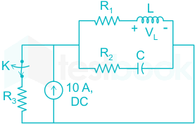
The value of parameters of the circuit shown in the figure are

R1 = 2Ω, R2 = 2Ω, R3 = 3Ω, L = 10 mH, C = 100 μF

For time t < 0, the circuit is at steady state with the switch ‘K’ in closed condition. If the switch is opened at t = 0, the value of the voltage across the inductor (VL) at t = 0+ in Volts is ____________ (Round off to 1 decimal place).

View answer & explanation

Correct answer

Answer: 8Answer: 8(±0.09999999999999964)

Why this answer is correct

At t = 0-, switch is closed and circuit is in steady state condition (inductor acts as short circuit and capacitor acts as open circuit).

By CDR, IL(0-) = \(10 × \frac{3}{3+2}=6 \mathrm{~A}\)

VC(0-) = 6 × 2 = 12 V

For t = 0+, switch is opened

Apply KVL,

6 × 2 + VL - 12 - 4 × 2 = 0

VL = 20 - 12

VL = 8V

Hence, the correct answer is 8V.

Question 20

GATE EE 2023• Electrical Engineering

A separately excited DC motor rated 400 V, 15 A, 1500 RPM drives a constant torque load at rated speed operating from 400 V DC supply drawing rated current. The armature resistance is 1.2 Ω. If the supply voltage drops by 10% with field current unaltered then the resultant speed of the motor in RPM is ____________ (Round off to the nearest integer).

View answer & explanation

Correct answer

Answer: 1342.5Answer: 1342.5(±2.5)

Why this answer is correct

Given torque is constant, T = KϕIa = Constant

Field is also unchanged, ϕ = Constant

So, Ia = Constant

The back emf with rated voltage

Eb1 = Vs - IaRa = 400 - 1.2 × 15

Eb1 = 382 V

and back emf with 10% drop in supply voltage

Eb2 = Vs - Ia2Ra = 400 × 0.90 - 1.2 × 15

Eb2 = 342 V

We know Eb ∝ N (for separately excited motor)

So, 

\( \frac{E_{b 2}}{E_{b 1}} =\frac{N_2}{N_1} \)

N2 = \(\frac{342}{382} \times 1500=1342.93\)

N2 = 1343 rpm