Previous Year Paper

BPSC AE Paper 5 (Civil) 11 Nov 2022 Official Paper (Previous Year Paper)

Held in 2022

50 questions60 minutes
With answers
Free

Paper last updated:

Practise under exam conditions

Take this paper as a timed mock test. Review your answers after you submit.

Attempt timed test

Questions & answers

Read the paper at your pace. Open an explanation when you need it.

Full Test (50 questions)

Question 1

Which expression represents shape factor?

  1. AOption (a)

    ZpZe \frac{Z_p}{Z_e}

  2. BOption (b)

    (MOB)p(MOB)e\frac{(M O B)_p}{(M O B)_e}

  3. COption (c)

    Both (1) and (2)

  4. DOption (d)

    None of the above

View answer & explanation

Correct answer

Answer: (c)C.

Both (1) and (2)

Why this answer is correct

Concept:

Shape Factor:

  • It represents the reserve of the strength of a section beyond the yield point.
  • It doesn't show the reserve of the strength of the complete structure.
  • It depends upon the geometry of the cross-section only.
  • It is defined as the ratio of the plastic moment capacity of a beam section to its yield moment capacity.

Mathematically,

\({\rm{S}}{\rm{.F = }}\dfrac{{{{\rm{M}}{\rm{p}}}}}{{{{\rm{M}}{\rm{y}}}}}{\rm{ = }}\dfrac{{{{\rm{f}}{\rm{y}}}{{\rm{Z}}{\rm{p}}}}}{{{{\rm{f}}{\rm{y}}}{\rm{Z}}}}{\rm{ = }}\dfrac{{{{\rm{Z}}{\rm{p}}}}}{{\rm{Z}}}\)

Where,

fy = Yield stress.

Zp = Plastic modulus of a section.

Z = Elastic modulus of a section.

Zp is calculated about the equal area axis and Z is calculated about the centroidal axis.

It can also be defined in terms of the moment of resistance under plastic and elastic conditions:

Shape Factor = (MOB)p/(MOB)e

(MOB​)p​ = Plastic moment of resistance

(MOB​)e​ = Elastic moment of resistance

Additional Information

Shape Factor for the different section:

Type of sectionShape factor
I – Section 1.12 - 1.14
Rectangular section 1.5
Hollow Circular section 1.27
Circular section 1.7
T-section 1.8
Diamond Section 2
Triangular Section 2.34

Question 2

The rotation at a point in a real beam is equal to ________ in a conjugate beam.

  1. AOption (a)

    twisting moment

  2. BOption (b)

    shear force

  3. COption (c)

    bending moment

  4. DOption (d)

    translation

View answer & explanation

Correct answer

Answer: (b)B.

shear force

Why this answer is correct

Concept-

Conjugate Beam Theorem-

Theorem 1: The slope or rotation at a point in the real beam is numerically equal to the shear force at the corresponding point in the conjugate beam.

Theorem 2: The displacement of a point in the real beam is numerically equal to the moment at the corresponding point in the conjugate beam.

Question 3

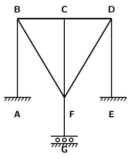
Calculate the number of zero force members for the following figure :

  1. AOption (a)

    3

  2. BOption (b)

    4

  3. COption (c)

    0

  4. DOption (d)

    2

View answer & explanation

Correct answer

Answer: (d)D.

2

Why this answer is correct

Explanation:

The number of zero force members is 2.

Additional InformationTo identify the zero force members in truss, the following rules are required to be used:

  1. If at a joint three members are meeting, two of which are collinear then force in third member is zero provide that no external load is acting on joint.
  2. If two non-collinear members are meeting at joint and no external load is acting on that joint, then force in both members is zero.

Question 4

Calculate the degree of indeterminacy of the frame structure given in the figure :

  1. AOption (a)

    9

  2. BOption (b)

    10

  3. COption (c)

    8

  4. DOption (d)

    12

View answer & explanation

Correct answer

Answer: (b)B.

10

Why this answer is correct

Explanation:

Degree of indeterminacy is given by

Ds = 3 x number of cuts required to make tree like structure fixed - number of reaction required to make joint

Ds = 3 x 4 - 2 = 10

Question 5

In a continuous beam ABC, support A is fixed and supports B and C are simply supported. A uniformly distributed load of w per meter run is applied over the span AB and span BC is subjected to a point load W at mid-span. If the beam has uniform cross-section but differs in span lengths for AB and BC, the conditions to be used for the analysis of continuous beam by the slope deflection method are

  1. AOption (a)

    θA = 0, MBA + MBC = 0, θC = 0

  2. BOption (b)

    θA = 0, MBA + MBC = 0, MCB = 0

  3. COption (c)

    θA = 0, MBA = MBC, MCB = 0

  4. DOption (d)

    θA = 0, MBA = MBC , θC = 0

View answer & explanation

Correct answer

Answer: (b)B.

θA = 0, MBA + MBC = 0, MCB = 0

Why this answer is correct

Concept:

To analyze a continuous beam using the slope deflection method, specific boundary conditions and equilibrium equations must be considered at each support. The conditions will differ based on the type of support and load applied to each span.

Given Beam:

  • Support A is fixed, implying θA=0 \theta_A = 0 .
  • Support B and Support C are simply supported, meaning no moment resistance at C (MCB=0 M_{CB} = 0 ).
  • Span AB has a uniformly distributed load w w per meter run.
  • Span BC has a point load W W at its mid-span.
  • The beam has a uniform cross-section but different span lengths for AB and BC.

Applying the Slope Deflection Method:

  • Fixed Support A: Since support A is fixed, the rotation θA \theta_A is zero.
  • Moment at Joint B: The sum of moments at B due to adjacent spans should be zero for equilibrium, giving MBA+MBC=0 M_{BA} + M_{BC} = 0 .
  • Simply Supported Support C: The moment at support C is zero (MCB=0 M_{CB} = 0 ) since it is simply supported.

Conditions for Analysis:

θA=0 \theta_A = 0

MBA+MBC=0M_{BA} + M_{BC} = 0

MCB=0M_{CB} = 0

Question 6

A frame to be analyzed by moment distribution as shown in the figure below :

The distribution factors for members EB, ED and EF will be respectively

  1. AOption (a)

    813,313,413\frac{8}{13}, \frac{3}{13}, \frac{4}{13}

  2. BOption (b)

    310,410,310\frac{3}{10}, \frac{4}{10}, \frac{3}{10}

  3. COption (c)

    411,411,311\frac{4}{11}, \frac{4}{11}, \frac{3}{11}

  4. DOption (d)

    29,49,13\frac{2}{9}, \frac{4}{9}, \frac{1}{3}

View answer & explanation

Correct answer

Answer: (c)C.

411,411,311\frac{4}{11}, \frac{4}{11}, \frac{3}{11}

Why this answer is correct

Concept:

Stiffness of a member is a measure of its resistance to deformation under load. The stiffness of a member in terms of flexural rigidity (EIEIEIEI

) and the length (ℓℓℓℓ

) is calculated using standard formulas for different boundary conditions and configurations.

The distribution factor (DF) is a coefficient used in the moment distribution method to distribute moments to various members connected at a joint based on their relative stiffness. It is calculated using the stiffness of each member.

Stiffness for Different Members:

Stiffness of member EB=4EIℓ \text{Stiffness of member EB} = \frac{4EI}{\ell}

=4E(2I)6=43EI = \frac{4E(2I)}{6} = \frac{4}{3}EI

Stiffness of member ED=4EI3 \text{Stiffness of member ED} = \frac{4EI}{3}

Stiffness of member EF=4EI4=EI \text{Stiffness of member EF} = \frac{4EI}{4} = EI

Distribution Factors for Different Members:

(DF)EB=43EI43EI+43EI+EI (DF)_{EB} = \frac{\frac{4}{3}EI}{\frac{4}{3}EI + \frac{4}{3}EI + EI}  =43EI43EI+43EI+EI=411 = \frac{\frac{4}{3}EI}{\frac{4}{3}EI + \frac{4}{3}EI + EI} = \frac{4}{11}

(DF)ED=43EI43EI+43EI+EI (DF)_{ED} = \frac{\frac{4}{3}EI}{\frac{4}{3}EI + \frac{4}{3}EI + EI}  =411 = \frac{4}{11}

(DF)EF=EI43EI+43EI+EI (DF)_{EF} = \frac{EI}{\frac{4}{3}EI + \frac{4}{3}EI + EI}  =311 = \frac{3}{11}

Question 7

"If an internal stress component like shear force, bending moment or reaction component is allowed to act through a small distance thereby causing deformation of the structure, the curve of the deformed shape represents to some scale, the influence line diagram for that stress or the reaction component."

The above statement is known as

  1. AOption (a)

    Müller-Breslau principle

  2. BOption (b)

    Castigliano's theorem

  3. COption (c)

    Maxwell's theorem

  4. DOption (d)

    Macaulay's theorem

View answer & explanation

Correct answer

Answer: (a)A.

Müller-Breslau principle

Why this answer is correct

concept:

According to Muller Breslau Principle:

“If an internal stress component (shear force, bending moment etc) or reaction component is allowed to act through a small distance thereby causing deformation of the structure, the curve of the deformed shape represents to some scale, the influence lines for that stress or the reaction component.”

Application: Muller-Breslau's Principle is applicable to all structures, determinate or indeterminate.

Note:

  • In the case of determinate systems, the ILD can be obtained directly by allowing unit deformation corresponding to the constraint.
  • For indeterminate structure, it is applicable only when the material is within the elastic limit and obeys Hook's law so that the law of superposition holds good.

This principle gives an excellent experiment approach to determine the influence lines for indeterminate structure.

∴ Influence lines can be drawn for all structures, determinate or indeterminate.

Question 8

An I section beam has the following dimensions :

Width of top flange = 250 mm 

Width of bottom flange = 400 mm

Thickness of both flanges = 50 mm

Width of web = 50 mm

Depth of web = 200 mm

The plastic neutral axis of the section from topmost fibre is at a distance of

  1. AOption (a)

    225 mm

  2. BOption (b)

    237.5 mm

  3. COption (c)

    262.2 mm

  4. DOption (d)

    210 mm

View answer & explanation

Correct answer

Answer: (a)A.

225 mm

Why this answer is correct

Concept:

To determine the location of the Plastic Neutral Axis (PNA) of an I-section beam, we need to find the point where the areas of the cross-section above and below this axis are equal. This is achieved by calculating the areas and balancing them around the PNA.

Given Data:

  • Width of top flange (bt b_t ) = 250 mm
  • Thickness of top flange (tt t_t ) = 50 mm
  • Width of bottom flange (bb b_b ) = 400 mm
  • Thickness of bottom flange (tb t_b ) = 50 mm
  • Width of web (bw b_w ) = 50 mm
  • Depth of web (dw d_w ) = 200 mm

Calculation:

1. Calculate the Area of Each Section:

  • Top flange area (At A_t ): 250,mm×50,mm=12500,mm2 250 , \text{mm} \times 50 , \text{mm} = 12500 , \text{mm}^2
  • Bottom flange area (Ab A_b ): 400,mm×50,mm=20000,mm2 400 , \text{mm} \times 50 , \text{mm} = 20000 , \text{mm}^2
  • Web area (Aw A_w ): 50,mm×200,mm=10000,mm2 50 , \text{mm} \times 200 , \text{mm} = 10000 , \text{mm}^2

2. Calculate the Total Area and Half Area:

Atotal=At+Ab+Aw=12500+20000+10000=42500,mm2 A_{\text{total}} = A_t + A_b + A_w = 12500 + 20000 + 10000 = 42500 , \text{mm}^2

Atotal2=425002=21250,mm2 \frac{A_{\text{total}}}{2} = \frac{42500}{2} = 21250 , \text{mm}^2

3. Determine the Distance from the Top Fiber:

  • Area of top flange: 12500,mm2 12500 , \text{mm}^2
  • Remaining area needed: 21250−12500=8750,mm2 21250 - 12500 = 8750 , \text{mm}^2
  • Web area per mm depth: 50,mm 50 , \text{mm}
  • Depth required in web: 875050=175,mm \frac{8750}{50} = 175 , \text{mm}

The plastic neutral axis is located at a distance of 50,mm+175,mm=225,mm 50 , \text{mm} + 175 , \text{mm} = 225 , \text{mm} from the topmost fiber.

Question 9

"For a given structure and loading, if there exists any distribution of bending moment throughout the section which is both safe and statically admissible with a set of loads W, the value of W must be less than or equal to the collapse load Wc."

The above theorem is known as

  1. AOption (a)

    kinematic theorem

  2. BOption (b)

    static theorem

  3. COption (c)

    uniqueness theorem

  4. DOption (d)

    None of the above

View answer & explanation

Correct answer

Answer: (b)B.

static theorem

Why this answer is correct

concept:

  • Static Theorem (also known as the Lower Bound Theorem of Plasticity):
  • The static theorem states that for a given structure and loading, if there exists a statically admissible distribution of bending moments that is both safe (does not exceed the plastic moment capacity) and in equilibrium with the applied loads, then the applied load WW W

W must be less than or equal to the collapse load WcWc W_c

  • In simpler terms, if you can find a moment distribution that satisfies equilibrium and does not exceed the material's yield criteria, then the structure will not collapse under that loading.

 Additional Information

  • Kinematic Theorem (Upper Bound Theorem):
  • This theorem states that for any assumed failure mechanism, the load calculated by equating the internal and external work done during the mechanism is an upper bound to the actual collapse load.
  • Uniqueness Theorem:
  • The uniqueness theorem asserts that if both a statically admissible stress distribution and a kinematically admissible mechanism predict the same collapse load, then that load is the true collapse load for the structure.

Question 10

The moment which makes all the fibres at the section to yield is known as

  1. AOption (a)

    moment of resistance

  2. BOption (b)

    plastic moment capacity

  3. COption (c)

    yield moment

  4. DOption (d)

    flexural rigidity

View answer & explanation

Correct answer

Answer: (b)B.

plastic moment capacity

Why this answer is correct

concept:

  • Plastic Moment Capacity:
  • The plastic moment capacity is the maximum moment that a cross-section can resist once it has fully yielded.
  • At this moment, the entire cross-section has reached the yield stress, and the section is in a fully plastic state.
  • This is an important concept in plastic analysis and design, where the strength of a structure is determined based on its ability to undergo large deformations before collapsing.

Additional Information

  • 1. Moment of Resistance:
  • The moment of resistance is the moment at which the internal stresses within a structural member balance the external forces. It can vary depending on whether the section is elastic, partially plastic, or fully plastic.
  • 2. Yield Moment:
  • The yield moment is the moment at which the first fiber of the cross-section reaches the yield stress. It is the moment that marks the transition from elastic behavior to plastic behavior, but not all fibers in the section are yielding yet.
  • 3. Flexural Rigidity:
  • Flexural rigidity is the product of the modulus of elasticity E the moment of inertia I of a section. It represents the resistance of a section to bending under an applied moment but is not directly related to the moment at which yielding occurs.

Question 11

The stiffness matrix of a beam is given as K[124 45]K\left[\begin{array}{cc}12 & 4 \ 4 & 5\end{array}\right]. Calculate the flexibility matrix.

  1. AOption (a)

    K[5−4 −412]K\left[\begin{array}{cc}5 & -4 \ -4 & 12\end{array}\right]

  2. BOption (b)

    144K[12−4 −45]\frac{1}{44 K}\left[\begin{array}{cc}12 & -4 \ -4 & 5\end{array}\right]

  3. COption (c)

    144K[5−4 −412]\frac{1}{44 K}\left[\begin{array}{cc}5 & -4 \ -4 & 12\end{array}\right]

  4. DOption (d)

    K[12−4 −45]K\left[\begin{array}{cc}12 & -4 \ -4 & 5\end{array}\right]

View answer & explanation

Correct answer

Answer: (c)C.

144K[5−4 −412]\frac{1}{44 K}\left[\begin{array}{cc}5 & -4 \ -4 & 12\end{array}\right]

Why this answer is correct

Explanation:

If we denote stiffness matrix as M and flexibility matrix as Δ

The flexibility matrix (F) is the inverse of the stiffness Matrix.

then flexibility matrix is: Δ = M-1

Calculation:

Δ = \frac{1}{{\left( {12\times5 - 4\times4} \right)}}\left[ {\begin{array}{*{20}{c}} 5&{ - 4}\ { - 4}&{12} \end{array}} \right]

∴ Δ = \frac{1}{{44}}\left[ {\begin{array}{*{20}{c}} 5&{ - 4}\ { - 4}&{12} \end{array}} \right]

Question 12

The shape factor of an I section is

  1. AOption (a)

    1.2

  2. BOption (b)

    1.5

  3. COption (c)

    2.0

  4. DOption (d)

    None of the above

View answer & explanation

Correct answer

Answer: (d)D.

None of the above

Why this answer is correct

Explanation:

Shape factor

  • It is defined as the ratio of the plastic moment to yield moment.
  • It is a function of cross-section or shape and is represented by ' f '.
  • f=MPMy=fyZPzfyZez=ZPzZezf = \frac{{{M_P}}}{{{M_y}}} = \frac{{{f_y}{Z_{Pz}}}}{{{f_y}{Z_{ez}}}} = \frac{{{Z_{Pz}}}}{{{Z_{ez}}}}

Shape factor for different cross-sectional shapes:

SectionShape factor
Triangular2.34
Diamond2
Rectangle / Square1.5
I - Section1.12 to 1.14
H - Section1.5
Circular hollow section1.27
Solid Circular section1.67

Question 13

Determine the load factor and factor of safety of a two-span continuous beam as shown in the figure below:

The plastic moment and elastic moment of the beam are 150 kN-m and 100 kN-m respectively.

  1. AOption (a)

    4.0 and 2.35

  2. BOption (b)

    6.0 and 4.0

  3. COption (c)

    4.0 and 4.35

  4. DOption (d)

    6.0 and 2.0

View answer & explanation

Correct answer

Answer: (b)B.

6.0 and 4.0

Why this answer is correct

Explanation:

Given Data:

Mp = 150 kN-m

Me = 100 kN-m

Collapse load for the each span of the given beam is

Wu = 6Mp/L1

Total Collapse load for the given beam is

Wu = (6Mp/L1)+(6Mp/L2) = 12Mp/5 = 12×150/5 = 360 kN

Working load on the given beam is 

Ww = 30 + 30 = 60 kN

Load Factor is 

= Wu/Ww = 360/60 = 6

Shape factor = Mp/Me = 150/100 = 1.5

FOS = Load factor/Shape factor = 6/1.5 = 4

Question 14

If t is the thickness of thinner plate in a bolted connection of tension member, pitch shall not be more than

  1. AOption (a)

    16t or 200 mm whichever is more

  2. BOption (b)

    12t or 150 mm whichever is less

  3. COption (c)

    12t or 150 mm whichever is more

  4. DOption (d)

    16t or 200 mm whichever is less

View answer & explanation

Correct answer

Answer: (d)D.

16t or 200 mm whichever is less

Why this answer is correct

concept:

As per the relevant IS code, for a built-up beam, the maximum pitch of rivets in the tension flange should not be more than lesser of 200 mm and 16t, where t is the thickness of the thinner outside plate.

This is applicable to any two adjacent rivets and rivets lying in a line parallel to the force in the member.

The minimum pitch should be 2.5 times the nominal diameter of the rivet

Question 15

In a roof truss a member normally acting as tension member but occasionally subjected to compression due to wind load, slenderness ratio should not exceed 

  1. AOption (a)

    250

  2. BOption (b)

    350

  3. COption (c)

    450

  4. DOption (d)

    150

View answer & explanation

Correct answer

Answer: (b)B.

350

Why this answer is correct

Maximum values of Effective Slenderness Ratios

Sl.   No.MemberMaximum Effective Slenderness Ratio (KL/r)
(i)A member carrying compressive loads resulting from dead loads and imposed loads180
(ii)A tension member in which a reversal of direct stress occurs due to loads other than wind or seismic forces180
(iii)A member subjected to compression forces resulting only form combination with wind/earthquake actions provided the deformation of such member does not adversely affect the stress in any part of the structure.250
(iv)Compression flange of a beam against lateral torsional buckling.300
(v)A member normal acting as a tie in a roof truss or a bracing system not considered effective when subject to possible reversal of stress into compression resulting from the action of wind or earthquake forces.350
(vi)Members always under tension (other than pre-tensioned members)400

Question 16

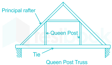
The truss shown in the figure below is known as

  1. AOption (a)

    Howe

  2. BOption (b)

    Fink

  3. COption (c)

    Pratt

  4. DOption (d)

    King poster

View answer & explanation

Correct answer

Answer: (b)B.

Fink

Why this answer is correct

Explanation:

King Post Truss - Span length up to 5 meter (i.e ≤ 5 meter )

Fink Truss - Span length is in between 5 to 10 meter

Queen Post Truss - Span length is in between 8 to 12 meter.

Howe Truss - Span length is in between 6 to 30 meter.

Question 17

If standard deviation is 4 N/mm2, the target mean strength of M20 concrete should be

  1. AOption (a)

    20 N/mm2

  2. BOption (b)

    24 N/mm2

  3. COption (c)

    26.4 N/mm2

  4. DOption (d)

    16 N/mm2

View answer & explanation

Correct answer

Answer: (c)C.

26.4 N/mm2

Why this answer is correct

Concept:

The correct expression as per IS 456: 2000 to find Target mean strength is:

fcm = fck + (1.65 × σ)

fcm = Target mean strength

fck = Characteristic strength

σ = Standard deviation

1.65 is generally a risk factor

Calculations:

fck = 20 N/mm2

σ = 4.0 N/mm2

Target mean strength is:

fcm = fck + (1.65 × σ)

fcm = 20 + (1.65 × 4)

fcm = 26.6 N/mm2

Question 18

IS 456 : 2000 considers concrete has reached its limit state of collapse when the strain is

  1. AOption (a)

    0.0020

  2. BOption (b)

    0.0030

  3. COption (c)

    0.0035

  4. DOption (d)

    0.0015

View answer & explanation

Correct answer

Answer: (c)C.

0.0035

Why this answer is correct

Explanation

These are the assumptions taken in the limit state of collapse: flexure-

  1. Plane section before bending remains plane even after bending
  2. The maximum strain in concrete at the outermost compression fiber is taken as 0.0035 in bending.
  3. Relationship between compressive stress distribution in concrete and strain in concrete may be assumed to be rectangular, trapezoidal, parabolic or any other shape which results in prediction of strength in substantial agreement with the result of test.
  4. The tensile strength of concrete is ignored
  5. The partial factor of safety for steel is taken as 1.15 and the stress in the steel are derived from stress strain curve.

Question 19

The centroid of a compression view block representing stress in concrete at limit state, the distance being measured from extreme compression edge is

where xu = depth of compression cone.

  1. AOption (a)

    0.42 xu

  2. BOption (b)

    0.48 xu

  3. COption (c)

    0.53 xu

  4. DOption (d)

    0.36 xu

View answer & explanation

Correct answer

Answer: (a)A.

0.42 xu

Why this answer is correct

Explanation:

Stress and Strain Diagram of a Singly Reinforced Beam in Limit State Method:

Where Xu = Actual depth of neutral axis

fck = Characteristic compressive strength of concrete

fy = Yield stress of steel

The centroid of the compressive force is at a distance of 0.42Xu from the extreme compression fibre.

Question 20

Limiting value of depth of neutral axis in RC beam of depth d with Fe250 steel is

  1. AOption (a)

    0.42 d

  2. BOption (b)

    0.48 d

  3. COption (c)

    0.53 d

  4. DOption (d)

    0.36 d

View answer & explanation

Correct answer

Answer: (c)C.

0.53 d

Why this answer is correct

Concept:

The ratio of limiting depth of neutral axis to the effective depth of the beam is given by

xud=Max;strain;concreteGrade;of;steelModulus;of;Elasticity;of;steel×F.O.S+0.002+Max;strain;concrete\frac{{{x_u}}}{d} = \frac{{{\rm{Max;strain;concrete}}}}{{\frac{{{\rm{Grade;of;steel}}}}{{{\rm{Modulus;of;Elasticity;of;steel}} \times {\rm{F}}.{\rm{O}}.{\rm{S}}}} + 0.002 + {\rm{Max;strain;concrete}}}}

Note:

Without getting into the tedious calculation,

We know the standard values of the ratio of limiting depth of neutral axis to the effective depth (k) of the beam for different steel sections as following:

Grade of SteelFe 500Fe 415Fe 250
‘k’ value0.460.480.53

Question 21

As per IS 456, in a column the maximum distance between two longitudinal bars should not greater than

  1. AOption (a)

    300 mm

  2. BOption (b)

    250 mm

  3. COption (c)

    350 mm

  4. DOption (d)

    200 mm

View answer & explanation

Correct answer

Answer: (a)A.

300 mm

Why this answer is correct

Concept:

As per IS 456: 2000, clause 26.5.3.1,

Longitudinal reinforcement in a column:

Spacing:

The spacing of longitudinal bars measured along the periphery of the column shall not exceed 300 mm.

Additional Information

Percentage of steel:

 The cross-sectional area of longitudinal reinforcement shall be not less than 0.8% nor more than 6% of the gross cross-sectional area of the column.

The minimum diameter of longitudinal reinforcement bars:

The main longitudinal reinforcement bars used in the column shall not be less than 12 mm in diameter.

The minimum number of longitudinal bar:

The minimum number of the longitudinal bar provided in the column shall be

  • four in rectangular columns
  • six in circular columns

Helical reinforcement:

A reinforced concrete column having helical reinforcement shall have at least six-bar of longitudinal reinforcement within the helical reinforcement.

Question 22

What is the effective length of the column when effectively restrained against translation at both the ends but restrained against rotation at one end only?

  1. AOption (a)

    0.81 L

  2. BOption (b)

    0.65 L

  3. COption (c)

    0.5 L

  4. DOption (d)

    0.707 L

View answer & explanation

Correct answer

Answer: (a)A.

0.81 L

Why this answer is correct

Explanation:

As per IS: 800 – 2007

For column, effectively restrained against translation at both the ends but restrained against rotation at one end only

Effective length is 0.8L

Design value of effective length factor for various combination are given below:

Question 23

In an RC beam main reinforcement consists of 16 mm bars and coarse aggregate size used is 20 mm. The horizontal distance between two parallel reinforcing bars should not be less than

  1. AOption (a)

    20 mm

  2. BOption (b)

    21 mm

  3. COption (c)

    25 mm

  4. DOption (d)

    16 mm

View answer & explanation

Correct answer

Answer: (c)C.

25 mm

Why this answer is correct

Concept:

As per IS456: 2000, cl. 26.3.2,

The horizontal distance between two parallel main reinforcing bars shall usually be not less than the greatest of the following –

  1. The diameter of the bar if the diameters are equal.
  2. The diameter of the larger bar if the diameters are unequal. 3. 5 mm more than the nominal maximum size of coarse aggregate.

Explanation:

Dia of main reinforcing bar = 16 mm

Size of coarse aggregate = 20 mm

The horizontal distance between two parallel reinforcing bars should not be less than greatest in the following:

  1. Diameter of the bar = 16 mm 2. 5 mm more than the nominal maximum size of coarse aggregate = 20 + 5 = 25 mm

So, the horizontal distance between two parallel reinforcing bars should not be less than 25 mm.

Question 24

The maximum area of tensile reinforcement to be used in a beam is to be restricted to

  1. AOption (a)

    0.04 × effective area of the section

  2. BOption (b)

    0.057 × gross area of the section

  3. COption (c)

    0.057 × effective area of the section

  4. DOption (d)

    0.04 × gross area of the section

View answer & explanation

Correct answer

Answer: (d)D.

0.04 × gross area of the section

Why this answer is correct

Area of steel reinforcement is regulated by the following norms:

i) Minimum area of steel (Astmin)=0.85fy×b×d\left( {{A_{s{t_{min}}}}} \right) = \frac{{0.85}}{{{f_y}}} \times b \times d

Minimum area of steel is to prevent any sudden failure and to provide minimum required ductility to the section.

ii) Maximum area of steel (Astmax)=4%\left( {{A_{s{t_{max}}}}} \right) = 4\% of gross area

Maximum area of steel is restricted, so as to avoid the problem of compaction while concreting.

Question 25

Pick up the correct statement about the design of a slab of dimension 7 m × 3 m. 

  1. AOption (a)

    Main reinforcement will be in 3 m direction and distribution in 7 m direction.

  2. BOption (b)

    Provide main reinforcement in 7 m direction and there is no need of distribution steel.

  3. COption (c)

    Provide main reinforcement in 3 m direction and there is no need of distribution steel.

  4. DOption (d)

    Main reinforcement will be in the direction 7 m and distribution reinforcement in 3 m.

View answer & explanation

Correct answer

Answer: (a)A.

Main reinforcement will be in 3 m direction and distribution in 7 m direction.

Why this answer is correct

Concept:

In the case of one-way slab, the slab bends primarily in one direction (shorter span), and reinforcement is provided accordingly.

According to IS 456:2000, a slab is considered a one-way slab if:

Longer span/Shorter span ​≥ 2

In this question:

7/3 ​= 2.33 ≥ 2 ⇒ One-way slab

Reinforcement Rule for One-Way Slab:

  • Main reinforcement is provided in the shorter direction (i.e., to resist bending in the longer span).
  • Distribution steel (secondary reinforcement) is provided in the longer direction to take care of temperature, shrinkage, and crack control.

🔹 But note: the slab bends along the longer direction (i.e., reinforcement is placed perpendicular to the direction of bending – hence in the shorter span).

For slab of 7 m × 3 m:

  • Main reinforcement = in 3 m direction (i.e., along the shorter span)
  • Distribution steel = in 7 m direction

Question 26

For a circular column of 200 mm radius, a circular footing of radius 1.25 m is provided. If the depth of footing is 600 mm and factored earth pressure is qu, the design two-way shear will be

  1. AOption (a)

    1.44 pqu

  2. BOption (b)

    1.3125 pqu

  3. COption (c)

    0.9225 pqu

  4. DOption (d)

    1.5225 pqu

View answer & explanation

Correct answer

Answer: (d)D.

1.5225 pqu

Why this answer is correct

Concept:

To calculate the design two-way shear (punching shear) for a circular column and footing, we use the formula based on the areas of the column and the footing.

Design Punching Shear=q0π(R2−r02) \text{Design Punching Shear} = q_0 \pi (R^2 - r_0^2)

Given Data:

  • Radius of the circular column, r0=200mm=0.2mr0=200mm=0.2m
  • Radius of the circular footing, R=1.25mR=1.25m
  • Depth of the footing, d=600mm=0.6md=600mm=0.6m
  • Factored earth pressure, ququ

Calculation:

1. Substitute the given values into the formula:

Design Punching Shear=quπ(1.252−0.22) \text{Design Punching Shear} = q_u \pi (1.25^2 - 0.2^2)

2. Calculate the squared values:

1.252=1.5625 1.25^2 = 1.5625 and 0.22=0.04 0.2^2 = 0.04

3. Substitute these values back into the formula:

Design Punching Shear=quπ(1.5625−0.04) \text{Design Punching Shear} = q_u \pi (1.5625 - 0.04)

Design Punching Shear=quπ(1.5225) \text{Design Punching Shear} = q_u \pi (1.5225)

The design two-way shear is approximately 1.5225πqu1.5225πqu

.

Question 27

Mortars used for brick masonry shall confirm generally to

  1. AOption (a)

    IS 456 : 2000

  2. BOption (b)

    IS 1332 : 1982

  3. COption (c)

    IS 2250 : 1981

  4. DOption (d)

    IS 2116 : 1980

View answer & explanation

Correct answer

Answer: (c)C.

IS 2250 : 1981

Why this answer is correct

Concept:

  • IS 2250:1981 specifies the code of practice for the preparation and use of masonry mortars. It outlines the guidelines for selecting the proportions, mixing, and application of mortars in masonry construction, ensuring the strength and durability of brick masonry work.

Additional Information

  1. IS 456:2000: This code of practice is for plain and reinforced concrete, providing guidelines for concrete mix design, construction, and maintenance. It does not directly relate to mortars used in brick masonry.
  2. IS 1332:1982: This standard specifies the composition and properties of phenolic resins for use in general-purpose molding powders. It is not related to masonry mortars.
  3. IS 2116:1980: This standard deals with sand for masonry mortars and plastering, specifying the requirements for sand used in these applications.

Question 28

Negative skin friction on piles is dominant in

  1. AOption (a)

    friction piles in soft clays

  2. BOption (b)

    friction piles in sands

  3. COption (c)

    friction per bearing piles

  4. DOption (d)

    piles resting on hard sands

View answer & explanation

Correct answer

Answer: (a)A.

friction piles in soft clays

Why this answer is correct

Concept:

Negative skin friction: It is usually a downward shear drag acting on a pile or pile group because of the downward movement of surrounding soil relative to the piles. Such a force can exist under one of the following conditions:

  1. If a fill of clay soil is placed over a granular soil layer into which a pile is driven, the fill will exert a downward drag force on the pile due to consolidation.
  2. If a fill of granular soil is placed over a layer of soft clay, it will induce the process of consolidation in the clay layer and thus exert a downward drag on the pile.
  3. Lowering of the water table will increase the vertical effective stress on the soil at any depth, so it can induce negative skin friction on piles.

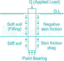
Now the axial capacity of a pile is the summation of upward reaction due to bearing at the base and net upward skin frictional resistance. As the negative skin friction (acting downward) lowers the net skin resistance, it, in turn, reduces the axial capacity of piles.

A schematic diagram of negative skin friction on piles is shown below:

∴ Negative skin friction on a pile under vertical compressive load acts downwards and reduce the load-carrying capacity.

Question 29

Higher density and a lower optimum water content is easily achieved by

  1. AOption (a)

    fine grained soil

  2. BOption (b)

    cohesion-less soil

  3. COption (c)

    saturated soil

  4. DOption (d)

    coarse grained soil

View answer & explanation

Correct answer

Answer: (d)D.

coarse grained soil

Why this answer is correct

Explanation:

Compaction Curve

  • A compaction curve is plotted between the water content as abscissa and the corresponding dry density as ordinate.
  • It is observed that the dry density initially increases with an increase in water content till the maximum density is attained. With a further increase in water content, the dry density decreases.
  • The water content corresponding to the maximum dry density is known as the optimum water content (O.W.C.) or the optimum moisture content (O.M.C.).

Important Points

  • The maximum dry density obtained increases with the increase in the compaction effort. The higher the compaction energy applied, the closer will be the packing of the materials leading to high dry density and low Optimum moisture content.
  • Since IS heavy compaction test (modified proctor test) imparts more compaction energy than the IS light compaction test (standard proctor test),
  • Fine soils have relatively more OMC but less maximum dry density compared to coarser soil because due to the high specific surface is more water is required for lubrication, hence showing a higher OMC.
  • Fine-grained soils have a higher void ratio, occupying more volume, and hence show a lesser value of maximum dry density compared to coarser soil.
  • The zero air voids line is the line that indicates an imaginary situation where there is no air in the soil and hence the air content in the soil is 0.

As Sr (Degree of saturation) + Ac (Air content) = 1, So the degree of saturation will be 1 for zero air content.


Question 30

Ratio of bearing capacity of double underreamed (UR) pile to that of single-reamed pile is nearly

  1. AOption (a)

    1.5

  2. BOption (b)

    1.2

  3. COption (c)

    1.7

  4. DOption (d)

    2

View answer & explanation

Correct answer

Answer: (a)A.

1.5

Why this answer is correct

Explanation

According to IS 2911: Part III 1973, the ratio of bearing resistance for the double under-reamed pile to that of a single under-reamed pile is 1.5 for sandy and clayey soils including black cotton soils.

Note:-

As per IS 2911: Part III (Some other recommendations)

  1. For deep deposits of expansive soils the minimum length of piles, irrespective of any other considerations shall be 3.5 m below the ground level. For recently filled-up grounds or other strata or poor bearing, the piles should pass through them and rest in good-bearing strata.
  2. The diameter of under-reamed piles may vary from 2 to 3 times the stem diameter depending upon the feasibility of construction. For Bored cast in situ under-reamed piles, the bulb diameter normally be 2.5 times while for compaction piles it is 2 times.
  3. For piles up to 30 cm in diameter, the spacing of bulbs should not be greater than 1.5 times the diameter of the bulb. For piles of diameter greater than 30 cm, spacing can be reduced to 1.25 times the stem diameter.
  4. The topmost bulb should be at a minimum depth of 2 times the bulb diameter. In expansive soils, it should not be less than 1.75 m below ground level. The minimum clearance below the underside of the pile cap is embedded in the ground and the bulb should be a minimum of 1.5 times the bulb diameter.
  5. Under-reamed piles with more than two bulbs are not advisable without ensuring their feasibility in strata needing stabilization of boreholes by drilling mud. The number of bulbs in case of bored compaction piles should not exceed tow in such strata.

Question 31

Stokes' law is applicable to soil particles of size between

  1. AOption (a)

    0.2 mm to 0.2 m

  2. BOption (b)

    0.3 mm to 3 m

  3. COption (c)

    0.2 mm to 2 m

  4. DOption (d)

    0.3 mm to 0.2 m

View answer & explanation

Correct answer

Answer: (a)A.

0.2 mm to 0.2 m

Why this answer is correct

Explanation:

Stokes Law

Assumptions

  • It is assumed that particles show discrete settling (i.e. grains of different sizes fall through a liquid at different velocities).
  • Particles assumed spherical in shape.
  • Medium is assumed infinite.
  • Particles size range 0.2 mm to 0.0002 mm.

Settling velocity,

Vs=(G−1)γwd18μ2{V_s} = {\frac{{(G - 1){γ _w}d}}{{18μ }}^2}

where,

G = specific gravity, γw = unit weight of water, d = diameter of particle, μ = dynamic viscosity

Additional Information

Limitations in the use of Stoke's Law in Sedimentation analysis:

  • Stoke's law is applicable for spherical particles only. The fine clay particles are not spherical in shape. While applying Stoke's law, the concept of equivalent diameter is used. The equivalent diameter of a soil particle is defined as the diameter of an imaginary sphere that has the same specific gravity as the soil particle and settles with the same terminal velocity as that of the soil particle.
  • It is assumed that every particle settles independently without interference from other particles as well as from the sides of the jar. To minimize error due to this assumption, it is recommended that not more than 50 gms of soil particles be taken in 1000 ml of soil suspension.
  • The soil particles in the soil suspension may have different values of specific gravity. But in the computations, an average value of G is used.
  • The lower limit of particle size for the validity of Stoke's Law is 0.0002 mm. However, the upper limit for the same is 0.2 mm. For particles of size less than 0.0002 mm, Brownian movement affects their settlement and in the case of particles larger than 0.2 mm, turbulence affects the settlement.
  • Stokes's law is valid upto a maximum Reynolds number of 1.

Question 32

If consistency index is zero, it means that the soil

  1. AOption (a)

    is at liquid limit

  2. BOption (b)

    behaves like liquid

  3. COption (c)

    is tiff

  4. DOption (d)

    is at plastic limit

View answer & explanation

Correct answer

Answer: (a)A.

is at liquid limit

Why this answer is correct

Consistency;index,;IC=wL−wwL−wPConsistency;index,;{I_C} = \frac{{{w_L} - w}}{{{w_L} - {w_P}}}

If IC=0;⇒w=wL;i.e;the;soil;is;in;liquid;limit.{I_C} = 0; \Rightarrow w = {w_L};i.e;the;soil;is;in;liquid;limit.

Question 33

Shear strength of soil increases with increase in

  1. AOption (a)

    cohesion of soil

  2. BOption (b)

    angle of internal friction

  3. COption (c)

    normal stress on soil

  4. DOption (d)

    All of the above

View answer & explanation

Correct answer

Answer: (d)D.

All of the above

Why this answer is correct

Concept:

Shear strength of soil is the capacity of soil to resist shearing stresses.  It can be defined as the maximum value of shear stress that can be mobilized within a soil mass. If this value exceeded by the shear stress on any plane or a surface at a point, failure will occur in soil because of movement of a portion of the soil mass along that particular plane. The soil is then said to be fail in shear.  Therefore, shear strength generally represented the strength of soil.

As per Mohr- Coulomb criteria, Shear strength of soil is given as:

τ = C + σ tanϕ

Where,

C is the Cohesion

σ is normal stress

ϕ is the friction angle

From above, it can be concluded that

a. It increases with an increase in the normal stress.

b. It is proportional to the cohesion of the soil i.e. increases with increase in cohesion.

c. it increases with increases in friction angle.

Question 34

In a tri-axial test when the drainage is allowed initially only and not during latter stage, the test is known as

  1. AOption (a)

    consolidated undrained test

  2. BOption (b)

    unconsolidated drained test

  3. COption (c)

    unconsolidated undrained test

  4. DOption (d)

    consolidated drained test

View answer & explanation

Correct answer

Answer: (a)A.

consolidated undrained test

Why this answer is correct

Explanation:

Types of Triaxial Test on the basis of Drainage:

(i) Unconsolidated Un-drained (UU) Test:

  • In this test expulsion of pore water is not permitted in both stages. It is used for clays in short-term analysis for clays under un-drained conditions at a fast loading rate
  • Due to undrained conditions in both the stages, the ϕ does not get mobilized and gives 0 value, which can be verified by drawing Mohr failure envelope for UU test.

From the above graph, we can conclude the ϕ is 0, for UU. As ϕ is defined as the slope of failure envelope and here the slope of failure envelope is 0

(ii) Consolidated Drained (CD) Test:  

  • In this test expulsion of pore water is permitted in both stages.
  • It is used for short-term and long-term stability analysis in saturated sands and long-term stability analysis in clays.

(iii) Consolidated Un-drained (CU) Test:

  • In this test, the expulsion of pore water is permitted in 1st stage but not in the second stage.
  • It is used for the investigation of the safety of the earthen dam which may occur due to the sudden drawdown of the water table.

Question 35

The coefficient of active earth pressure for a dense sand is 1/3. Then coefficient of passive earth pressure is

  1. AOption (a)

    1/3

  2. BOption (b)

    1

  3. COption (c)

    3

  4. DOption (d)

    None of the above

View answer & explanation

Correct answer

Answer: (c)C.

3

Why this answer is correct

Explanation:

Given data,  coefficient of active earth pressure, Ka= 1/3

We know that, Ka×Kp=1K_a \times K_p = 1

from the above,

Kp=113=3K_p = \frac{1}{\frac{1}{3}} = 3

The coefficient of passive pressure Kp is 3.

Additional InformationActive earth pressure:

It is the minimum pressure acting on the wall when the wall moves away from, the backfill.

Passive earth pressure:

It is the maximum pressure acting on the wall when the wall moves towards the backfill.

Question 36

According to IS specifications in any case depth of foundation in sand and clay should not be less than _________ respectively.

  1. AOption (a)

    800 mm and 900 mm

  2. BOption (b)

    900 mm and 1000 mm

  3. COption (c)

    1000 mm and 1200 mm

  4. DOption (d)

    600 mm and 800 mm

View answer & explanation

Correct answer

Answer: (a)A.

800 mm and 900 mm

Why this answer is correct

Explanation:

As per Cl. 7.2, IS:1904,

All foundations shall extend to a depth of at least 50 cm below the natural ground level.

The minimum depth of footing on sandy soil is 0.8 - 1 m, for rocky soil, it is 0.05 - 0.5 m and for clayey soil, it is 0.9 - 1.6 m.

The minimum depth of foundation for the load-bearing wall is 900 mm.

Important Points

The design of building foundations is performed based on prescribed serviceability and strength criteria laid down by various standard codes adopted by different countries.

Generally, the total settlement of a foundation is described under the serviceability criterion; whereas a strength criterion is described by bearing capacity of the soil or rock underlying the foundation.

As per Rankine formula, minimum depth of foundation is given as

Df=qγ×(1−sinϕ1+sinϕ)2{{\rm{D}}_{\rm{f}}} = \frac{{\rm{q}}}{{\rm{\gamma }}} \times {\left( {\frac{{1 - {\rm{sin}}\phi }}{{1 + {\rm{sin}}\phi }}} \right)^2}

Where,

q = Gross bearing capacity, γ = Unit weight of soil, and ϕ = Angle of internal friction of soil

Question 37

When width of foundation is 900 mm, the settlement is found to be 30 mm. Under the same condition, if width of footing is 600 mm, the settlement will be

  1. AOption (a)

    30 mm

  2. BOption (b)

    20 mm

  3. COption (c)

    10 mm

  4. DOption (d)

    None of the above

View answer & explanation

Correct answer

Answer: (b)B.

20 mm

Why this answer is correct

Calculation

 Width of footing (B1)= 900 mm, Settlement of footing (S1) = 30 mm

 Width of footing (B2) = 600 mm, Settlement of plate (S2) = ?

Under the same condition,

considering, Settlement in case of clay is given by

SfSp=BfBp\frac{{{S_f}}}{{{S_p}}} = \frac{{{B_f}}}{{{B_p}}}

S2S1=B2B1\frac{{{S_2}}}{{{S_1}}} = \frac{{{B_2}}}{{{B_1}}}

S2=600×30900S_2= {{600\times 30} \over 900}

Sf = 20 mm

Question 38

In plate load test preloading recommended by IS 1888 : 1982 is

  1. AOption (a)

    100 gm/cm2

  2. BOption (b)

    120 gm/cm2

  3. COption (c)

    125 gm/cm2

  4. DOption (d)

    70 gm/cm2

View answer & explanation

Correct answer

Answer: (d)D.

70 gm/cm2

Why this answer is correct

concept:

A minimum seating pressure or preload of 70 g/cm2 (0.7 t/m2), shall be applied and removed before starting the load test.

Then the load is applied with regular increment, using hydraulic jacks. Usually the increment is about 1/5th of the estimated safe bearing capacity of the soil.

Question 39

Which of the following is the cube size used for laboratory test on compressive strength of cement?

  1. AOption (a)

    100 mm

  2. BOption (b)

    70.6 mm

  3. COption (c)

    200 mm

  4. DOption (d)

    150 mm

View answer & explanation

Correct answer

Answer: (b)B.

70.6 mm

Why this answer is correct

Explanation:

According to IS: 10080 - 1982, the cube size recommended for compressive strength of cement is 70.6 mm, whereas, for concrete cube, the standard size is 150 mm.

Important Points

  • A Cement-sand mortar mix of 1:3 is prepared and water is added at 10% of the weight of both cement and sand. In general, 200 grams of cement is used.
  • Water content is P/4 +3.5 (P= standard consistency).
  • Cubes are kept at a temperature 20 ± 1 0C and at a relative humidity of not less than 90% for 24 ± 0.5 hours.
  • Total 3 cubes are tested for compressive strength and the average of three corresponding values is taken as the compressive strength of cement.

So the answer is 70.6 mm.

Question 40

What is the loading rate used in compressive strength test of bricks?

  1. AOption (a)

    14 N/mm2 per minute

  2. BOption (b)

    20 N/mm2 per minute

  3. COption (c)

    40 N/mm2 per hour

  4. DOption (d)

    14 N/mm2 per hour

View answer & explanation

Correct answer

Answer: (a)A.

14 N/mm2 per minute

Why this answer is correct

Concepts:

Procedure for determining the compressive strength of brick as per IS 3495:

Step 1:

Place the specimen with flat faces horizontal, and mortar-filled face facing upwards between two 3-ply plywood sheets each of 3 mm thickness and carefully centered between plates of the testing machine.

Step 2:

Apply load axially at a uniform rate of 14 N/mm2 per minute till failure occurs and note the maximum load at failure. The load at failure shall be the maximum load at which the specimen fails to produce any further increase in the indicator reading on the testing machine.

Step 3:

Repeat the above steps for 5 nos. of bricks and their average value is reported.

Question 41

What is the depth should the needle in Vicat apparatus penetrate into the cement paste die in consistency test?

  1. AOption (a)

    33 - 35 mm from top of the moulde

  2. BOption (b)

    33 - 35 cm from top of the mould

  3. COption (c)

    33 - 35 cm from bottom of the mould

  4. DOption (d)

    33 - 35 mm from bottom of the mould

View answer & explanation

Correct answer

Answer: (a)A.

33 - 35 mm from top of the moulde

Why this answer is correct

Explanation:

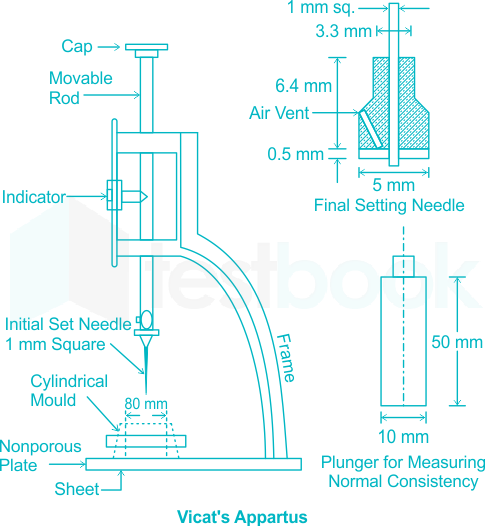
Vicat’s Apparatus

  • It is used to find out the consistency, initial setting time and final setting time of the cement.
  • In the normal consistency test, we have to find out the amount of water to be added to the cement to form a cement paste of normal consistency.
  • Vicat's apparatus consists of an arrangement to hold the plunger of 10 mm diameter and two other needles which are made to freely fall into a mold filled with the cement paste and the amount of penetration of the needles of plunder can be noted using the vertical graduations from 0 mm to 50 mm.
  • The length of the needle varies from 40 mm to 50 mm.
  • Standard consistency is defined as the consistency of the cement paste that permits the penetration of circular vicat’s plunger of 10 mm dia and height 50 mm up to the depth of 5 - 7 mm from the bottom into the mould or 33 to 35 mm from the top of the mould.
  • The needle of diameter 1 mm is used and the center needle of the attachment of the Vicat plunger projects the circular cutting edge by 0.5 mm as can be observed in the figure below:

Question 42

The minimum strength of brick required for building wall is

  1. AOption (a)

    5.0 N/mm2

  2. BOption (b)

    3.5 N/mm2

  3. COption (c)

    2.5 N/mm2

  4. DOption (d)

    7.5 N/mm2

View answer & explanation

Correct answer

Answer: (b)B.

3.5 N/mm2

Why this answer is correct

Explanation

As per IS 1077: 1992 code, the common burnt clay bricks are classified into various classes based on their average compressive strength as mentioned below in the tabulated form:

Brick Class DesignationAverage compressive or crushing strength in MPa
3535
3030
2525
2020
17.517.5
1515
12.512.5
1010
7.57.5
55
3.53.5


It is clear from above table that, the minimum crushing strength of common brunt clay brick is 3.5 MPa.

Question 43

Gypsum is added during the manufacture of cement

  1. AOption (a)

    during burning in the kiln

  2. BOption (b)

    at the beginning of grinding the clinker

  3. COption (c)

    after grinding the clinker

  4. DOption (d)

    while mixing the raw materials

View answer & explanation

Correct answer

Answer: (b)B.

at the beginning of grinding the clinker

Why this answer is correct

concept:

The main function of gypsum in the cement is to prevent flash set of cement.

During the grinding of clinker, gypsum or plaster of paris (CaSo4) is added to adjust the setting time. The amount of gypsum is about 3% by weight of clinker. It improves the soundness of cement.

The compound C3A is characteristically fast reacting with water and may lead to an immediate stiffening of paste and this process is termed as flash set. The role of gypsum added in the manufacture of cement is to prevent such a fast reaction.

Question 44

Indian standard specifications for estimating tensile strength and modulus of elasticity of concrete, if the characteristic strength fck is known, respectively are

  1. AOption (a)

    0.7fck0.7 \sqrt{f_{c k}} and 5000 fck\sqrt{f_{c k}}

  2. BOption (b)

    0.75fck0.75 f_{c k} and 7000fck7000 f_{c k}

  3. COption (c)

    0.7fck0.7 f_{c k} and 5000fck5000 f_{c k}

  4. DOption (d)

    0.75fck0.75 \sqrt{f_{c k}} and 7000fck7000 \sqrt{f_{c k}}

View answer & explanation

Correct answer

Answer: (a)A.

0.7fck0.7 \sqrt{f_{c k}} and 5000 fck\sqrt{f_{c k}}

Why this answer is correct

CONCEPT:

As per IS 456: 2000,

The Short term Static Modulus of elasticity of concrete Ec is given as-

\({{\rm{E}}{\rm{c}}} = 5000{\rm{;}}\sqrt {{{\rm{f}}{{\rm{ck}}}}} \)

Where,

fck = characteristic compressive strength of concrete,

fck and Ec are measured in MPa.

As per IS 456:2000, the flexural tensile strength of concrete = 0.7fck0.7\sqrt {{{\rm{f}}_{{\rm{ck}}}}}

Where, fck = 28 days characteristic compressive strength of concrete, which is the full strength of the concrete

Flexural tensile strength of concrete is always lesser than its characteristics compressive strength and it increases with an increase in the grade of the concrete.

Question 45

The absolute bending moment in a simply supported beam of span 10 m due to a moving load of 40 kN/m spanning over 5 m is

  1. AOption (a)

    375 kN-m at midpoint

  2. BOption (b)

    375 kN-m at 3.75 m from end A

  3. COption (c)

    500 kN-m at mid-span

  4. DOption (d)

    375 kN-m at 2.5 m from end A

View answer & explanation

Correct answer

Answer: (a)A.

375 kN-m at midpoint

Why this answer is correct

Explanation:

The absolute maximum bending moment will occur at the centre when the load is spread equally on either side of the centre.

Mmax;=;wa4(L−a2) ;=;40×54×(10−52)\begin{array}{l} {M_{max}}; = ;\frac{{wa}}{4}\left( {L - \frac{a}{2}} \right)\ ; = ;\frac{{40 \times 5}}{4} \times \left( {10 - \frac{5}{2}} \right) \end{array}

= 50 × 7.5 = 375 KN-m at centre

Question 46

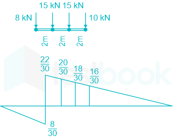
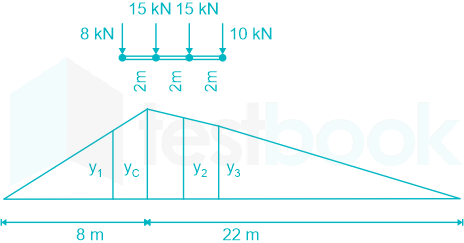
Four point loads 8 kN, 15 kN, 15 kN and 10 kN have centre-to-centre spacing of 2 m between consecutive loads and they traverse a girder of 30 m span from left to right with 10 kN load loading. The maximum shear force at 8 m from left support will be

  1. AOption (a)

    25.4 kN

  2. BOption (b)

    30.2 kN

  3. COption (c)

    42.2 kN

  4. DOption (d)

    8.2 kN

View answer & explanation

Correct answer

Answer: (b)B.

30.2 kN

Why this answer is correct

Concept:

To determine the maximum positive shear force at a specific point on a girder, we analyze the effect of different point loads on the shear force at that point. The shear force is calculated by considering the contribution of each load based on its position relative to the point of interest.

Given Data:

  • Point Loads: 10 kN, 15 kN, 15 kN, and 8 kN
  • Center-to-center spacing between loads: 2 m
  • Span of the girder: 30 m
  • Point of interest for shear force: 8 m from left support

Calculation:

1. Shear Force with 8 kN Load:

SF=10×830+15×630+15×430+8×230 \text{SF} = 10 \times \frac{8}{30} + 15 \times \frac{6}{30} + 15 \times \frac{4}{30} + 8 \times \frac{2}{30}

SF=8.2,kN \text{SF} = 8.2 , \text{kN}

2. Maximum Positive Shear Force Calculation:

SF=10×1630+15×1830+15×2030+8×2230 \text{SF} = 10 \times \frac{16}{30} + 15 \times \frac{18}{30} + 15 \times \frac{20}{30} + 8 \times \frac{22}{30}

SF=30.2,kN \text{SF} = 30.2 , \text{kN}

3. Check for Another Load Position (15 kN Load on the Section):

SF=10×1830+15×2030+15×2230−8×630 \text{SF} = 10 \times \frac{18}{30} + 15 \times \frac{20}{30} + 15 \times \frac{22}{30} - 8 \times \frac{6}{30}

SF=25.4,kN \text{SF} = 25.4 , \text{kN}

The maximum positive shear force is 30.2 kN.

Question 47

Which structure is more stable?

  1. AOption (a)

    Indeterminate

  2. BOption (b)

    Determinate

  3. COption (c)

    Both (1) and (2)

  4. DOption (d)

    None of the above

View answer & explanation

Correct answer

Answer: (a)A.

Indeterminate

Why this answer is correct

Explanation:

Stability:

  1. Determinate Structures:
  • A determinate structure is one in which the reactions and internal forces can be determined solely by using the equations of static equilibrium (i.e., the sum of forces and moments equals zero).
  • These structures are stable under standard load conditions and are easier to analyze because they do not involve complex compatibility conditions.
  • However, determinate structures lack redundancy, meaning that if one element fails, the whole structure can become unstable.
  1. Indeterminate Structures:
  • An indeterminate structure has more supports or internal members than necessary for equilibrium, leading to additional unknown forces that cannot be determined by static equilibrium alone. These require additional compatibility equations.
  • Indeterminate structures are generally more stable because they have redundancy. If one element fails or if unexpected loads are applied, other elements can redistribute the forces, maintaining the overall stability of the structure.
  • This redundancy provides enhanced safety against unexpected loading conditions, making indeterminate structures more resilient and stable compared to determinate structures.

Based on standard structural analysis theory:

  • Indeterminate structures are typically considered more stable due to their redundancy, which allows for load redistribution and provides a safeguard against failure.

Question 48

The strain energy of a structure due to bending is given by

  1. AOption (a)

    13∫M2dxEI\frac{1}{3} \int \frac{M^2 d x}{E I}

  2. BOption (b)

    12∫M2dxEI\frac{1}{2} \int \frac{M^2 d x}{E I}

  3. COption (c)

    ∫M2dxEI \int \frac{M^2 d x}{E I}

  4. DOption (d)

    2∫M2dxEI2 \int \frac{M^2 d x}{E I}

View answer & explanation

Correct answer

Answer: (b)B.

12∫M2dxEI\frac{1}{2} \int \frac{M^2 d x}{E I}

Why this answer is correct

Concepts:

The strain energy is the energy stored in a body due to its elastic deformation.

The most general formula for strain energy is:

U=12×F×δU = {\frac{1}{2}} \times F \times \delta

Where, F is the applied force and δ is deformation

However, When stress σ is proportional to strain, ϵ, the strain energy formula is: 

   U=12×V×σ×ϵU = {\frac{1}{2}} \times V \times \sigma \times \epsilon; V is the volume of material.

Based on the above formals, the strain energy stored in the material due to different types of forces/moments is given as:

  1. Strain energy due to bending is:

   U=∫M22EIdxU = \int\frac{M^{2}}{2EI}dx

  1. Strain energy due to Torsion is :

    U=∫T2L2GJdxU = \int\frac{T^2L}{2GJ}dx

Question 49

Total distribution factor for a rigid joint is always

  1. AOption (a)

    0.5

  2. BOption (b)

    1.5

  3. COption (c)

    0

  4. DOption (d)

    1

View answer & explanation

Correct answer

Answer: (d)D.

1

Why this answer is correct

Concept:

Distribution factor (DF):

DF=Stiffness,of,a,memberSum,of,stiffness,of,all,members,at,that,jointDF={Stiffness, of, a, member\over Sum, of, stiffness, of , all, members, at, that , joint}

Or

DF=Relative,stiffness,of,a,membersum,of,relative,stiffness,of,all,members,at,that,jointDF={Relative, stiffness, of, a, member\over sum, of, relative, stiffness, of , all, members, at, that , joint}


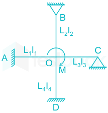
Where M1, M2, M3, and M4 are moment induced in member OA, OB, OC, and OD respectively.

The summation of DF for all members at a joint is one.

Question 50

A beam carries a uniform distributed load through its length. In which of the following configurations will the strain energy be maximum?

  1. AOption (a)

    Fixed

  2. BOption (b)

    Simply supported

  3. COption (c)

    Propped cantilever

  4. DOption (d)

    Cantilever

View answer & explanation

Correct answer

Answer: (d)D.

Cantilever

Why this answer is correct

Concept:

Strain energy:

It is defined as the energy adsorption of material due to strain under an applied load. It is also equal to the work done on a specimen by an external force. It can be denoted by U.

{\bf{U}} = \mathop \smallint \limits_0^{\bf{L}} \frac{{{{\bf{M}}^2}{\bf{dx}}}}{{2{\bf{EI}}}}

Where,

M = Maximum moment, E = Elastic modulus, I = Moment of inertia.

Explanation:

Strain energy will be maximum when the maximum moment will be high.

Maximum moment for different types of beam:

For the cantilever beam, M=WL22{\bf{M}} = \frac{{{\bf{W}}{{\bf{L}}^2}}}{2}

For Fixed-beam, M=WL212{\bf{M}} = \frac{{{\bf{W}}{{\bf{L}}^2}}}{{12}}

For simply supported beam, M=WL28{\bf{M}} = \frac{{{\bf{W}}{{\bf{L}}^2}}}{8}

For propped cantilever beam, M=WL28{\bf{M}} = \frac{{{\bf{W}}{{\bf{L}}^2}}}{8}

Hence, Strain energy for the uniformly distributed load will be maximum in the cantilever beam.

50 questions in the full paper