Official Paper

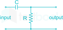
GATE EE 2021 Official Paper (Previous Year Paper)

65 questions · 180 minutes · with answers · free

General Aptitude (10 questions)

1

<br>

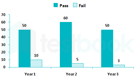
The number of students passing of failing in an exam for a particular subject is presented in the bar chart above. Students who pass the exam cannot appear for the exam again. Students who fail the exam in the first attempt must appear for the exam in the following year. Students always pass the exam in their second attempt.

The number of students who took the exam for the first time in the year year 2 and the year 3 respectively, are ______

  1. ((a))

    55 and 48

  2. ((b))

    60 and 50

  3. ((c))

    65 and 53

  4. ((d))

    55 and 53

Show Answer
Answer: ((a))

55 and 48

Given data from the chart,

YearPassFailTotal
1501060
260565
250353
<br>

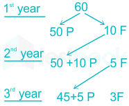
Fail in the first year will give an exam in the second year.

Students will pass on 2nd attempt.

It means fail in 1st year students will become pass in 2nd year.

The number of students who took the exam for the first time in the year 2nd = 50 + 5 = 55

The number of students who took the exam for the first time in the year 3rd = 45 + 3 = 48

2

Let X be a continuous random variable denoting the temperature measured. The range of temperature is [0, 100] degree Celsius and let the probability density function of X be f(x) = 0.01 for 0 ≤ X ≤ 100.

The mean of X is ______

  1. ((a))

    5.0

  2. ((b))

    2.5

  3. ((c))

    25.0

  4. ((d))

    50.0

Show Answer
Answer: ((d))

50.0

Concept:

The mean or expectation of a continuous random variable is given by

\(E\left( x \right) = \mathop \smallint \limits_{ - \infty }^\infty xf\left( x \right)dx\)

Where f(x) is the probability density function (PDF).

Application:

Given probability density function of X 

f(x) = 0.01 for 0 ≤ X ≤ 100

The mean or expectation of a continuous random variable is given by

\(E\left( x \right) = \mathop \smallint \limits_{ 0}^{100} x\left( 0.01 \right)dx=50\)

Additional Information

 Properties of a valid probability density function (PDF):

1) fX(x)0,;;x;ϵ;R{f_X}\left( x \right) \ge 0,;\forall ;x;\epsilon;R

∴ PDF will be bounded between 0 and 1.

2) \(\mathop \smallint \limits_{ - \infty }^\infty {f_X}\left( x \right)dx = {F_X}\left( \infty \right) = 1\)

3) \({F_X}\left( \infty \right) = \begin{array}{*{20}{c}} {{\rm{lim}}}\ {x \to \infty } \end{array}{F_X}\left( x \right)\)

∴ PDF will always be a monotonically increasing function as the probability is always greater than or equal to 0.

3

The people ______ were at the demonstration were from all sections of society.

  1. ((a))

    who

  2. ((b))

    which

  3. ((c))

    whom

  4. ((d))

    whose

Show Answer
Answer: ((a))

who

The correct answer is 'who'.

Key Points

We use who to refer to the subject of a sentence.

  • In the above sentence, 'The people' is the subject of the sentence.
  • Thus, we will use the pronoun 'who' as we are referring to the subject 'The people'.

Additional Information

Pronouns are words that take the place of a noun. 

  • Relative pronouns are used at the beginning of an adjective clause (a dependent clause that modifies a noun).
  • The relative pronouns are "that," "which," "who," "whom," and "whose."
  • "Whom" is an object pronoun like "him," "her" and "us."  We use "whom" to ask which person receives an action.
  • "Whose" is a possessive pronoun like "his," "her" and "our." We use "whose" to find out which person something belongs to.
  • We use "Which" is used for animals in general or things.
4

Which one of the following numbers is exactly divisible by (1113 + 1)?

  1. ((a))

    1139 - 1

  2. ((b))

    1133 + 1

  3. ((c))

    1126 +1

  4. ((d))

    1152 - 1

Show Answer
Answer: ((d))

1152 - 1

Concept:

(an - bn) is divisible by (a+b), only when 'n' is even.

Application: 

115211113+1=(1113)4141113+1\dfrac {{11^{52}-1}} {{11^{13}+1}}=\dfrac {({{11^{13})}^4-1^4}}{{11^{13}+1}}

⇒ 115211113+1=[(1113)212][(1113)2+12]1113+1\dfrac {{11^{52}-1}}{{11^{13}+1}}=\dfrac {{[{{{(11^{13})}^2}-1^2}][{{{(11^{13})}^2}+1^2}]}}{{{{11^{13}}}+1}}

⇒ 115211113+1=[11131][1113+1][(1113)2+12]1113+1\dfrac {{11^{52}-1}}{{11^{13}+1}}=\dfrac {{[{{{11^{13}}}-1}][{{{11^{13}}}+1}][{{{(11^{13})}^2}+1^2}]}}{{{{11^{13}}}+1}}

⇒ 115211113+1=[11131][(1113)2+1]\dfrac {{11^{52}-1}}{{11^{13}+1}}=[11^{13}-1][{({11^{13})}^2}+1]

∴ (1152 - 1) is exactly divisible by (1113 + 1)

5

The importance of sleep is often overlooked by students when they are preparing for exams. Research has consistently shown that sleep deprivation greatly reduces the ability to recall the material learnt. Hence, cutting down on sleep to study longer hours can be counterproductive.

Which one of the following statement is the CORRECT inference from the above passage?

  1. ((a))

    To do well in an exam, adequate sleep must be part of the preparation.

  2. ((b))

    If a student is externally well prepared for an exam, he needs little or no sleep.

  3. ((c))

    Students are efficient and are not wrong in thinking that sleep is a waste of time.

  4. ((d))

    Sleeping well alone is enough to prepare for an exam. Studying has lesser benefit.

Show Answer
Answer: ((a))

To do well in an exam, adequate sleep must be part of the preparation.

The correct answer is ​To do well in an exam, adequate sleep must be part of the preparation.

Key Points

  • Look at the lines: Research has consistently shown that sleep deprivation greatly reduces the ability to recall the material learnt. Hence, cutting down on sleep to study longer hours can be counterproductive.
  • Upon the perusal of the above lines, it can be concluded that adequate sleep is needed to do well in the exam as it increases the ability to recall the material learnt.
  • Hence, option 1 is the most appropriate answer choice.

Additional Information

  • Overlook: to fail to notice or consider something
  • Deprivation:  a situation in which you do not have things or conditions that are usually considered necessary for a pleasant life
  • Counterproductive: having an effect that is the opposite of what you intend or desire
6

Seven cars P, Q, R, S, T, U and V are parked in a row not necessarily in that order. The cars T and U should be parked next to each other. The cars S and V also should be parked next to each other, whereas P and Q cannot be parked next to each other. Q and S must be parked next to each other. R is parked to the immediate right of V. T is parked to the left of U.

Based on the above statements, the only INCORRECT option given below is:

  1. ((a))

    V is the only car parked in between S and R.

  2. ((b))

    Car P is parked at the extreme end.

  3. ((c))

    Q and R are not parked together.

  4. ((d))

    There are two cars parked in between Q and V.

Show Answer
Answer: ((d))

There are two cars parked in between Q and V.

The arrangement can be written as,

Arrangement 1: Cars S and V also should be parked next to each

Arrangement 2: P and Q cannot be parked next to each other.

Arrangement 3: Q and S must be parked next to each other.

Arrangement 4: R is parked to the immediate right of V.

Arrangement 5: T is parked to the left of U.

From Arrangement 1 and Arrangement 4 the arrangement will be,

From Arrangement 3,

From Arrangement 2 and Arrangement 5 the final arrangement will be,

Conclusion:

V is the only car parked in between S and R: Right

Car P is parked at the extreme end: Right

Q and R are not parked together: Right

There are two cars parked in between Q and V: Wrong

7

Oasis is to sand as island is to ______

Which one of the following options maintains a similar logical relation in the above sentence?

  1. ((a))

    Mountain

  2. ((b))

    Water

  3. ((c))

    Stone

  4. ((d))

    Land

Show Answer
Answer: ((b))

Water

The correct answer is Water.

Key Points

  • An Oasis is a small fertile or green (wet) area that springs up out of the desert. Desert is covered with sand.
  • An Island is a small land (dry) area that springs up out of the ocean. Ocean is filled with water.

Thus, Oasis is to sand as island is to water. This maintains a similar logical relation.

8

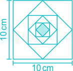
In the figure shown above, each square is formed by joining the midpoints of the sides of the next larger square. The area of the smallest square (shaded) as shown, in cm2 is:

  1. ((a))

    3.125

  2. ((b))

    1.5625

  3. ((c))

    6.25

  4. ((d))

    12.50

Show Answer
Answer: ((a))

3.125

Length of the side of larger square L1 = 10 cm

The first small square is cutting midway of the larger square, so  L2=102;cmL_2={10\over \sqrt 2}; cm

The second small square is cutting midway of the first small square, so L3=10(2)2;cmL_3={{10\over (\sqrt 2)^2}}; cm

Similarly, 5 square are made, so the length of the smallest square L6=10(2)5;cmL_6={{10\over (\sqrt 2)^5}}; cm

Area of the smallest square = (L6)2 = [10(2)5]2;(cm)2=3.125;cm2[{{10\over (\sqrt 2)^5}}]^2; (cm)^2 = 3.125;{cm}^2

The area of the smallest square (shaded) = 3.125 cm2

Area of largest square = 100 cm2

The first small square is dividing in half, so its area = 1002;cm2{100\over 2};{cm}^2

Similarly, 5 squares are made, area of smallest square = 10025;cm2=3.125;cm2{100\over 2^5};{cm}^2 = 3.125;{cm}^2

9

For a regular polygon having 10 sides, the interior angle between the sides of the polygon, in degrees, is:

  1. ((a))

    216

  2. ((b))

    324

  3. ((c))

    144

  4. ((d))

    396

Show Answer
Answer: ((c))

144

Concept:

The formula for the interior angle (θi) of a 'n' side regular polygon:

 θi=(n2)n×180θ _i={{(n-2)\over n}\times180}

Calculation:

Given:

n = 10

θi=(102)10×180=144\theta _i={{(10-2)\over 10}\times180} = 144

∴ The interior angle = 144°

10

A transparent square sheet shown above is folded along the dotted line. The folded sheet will look like ______

  1. ((a))

  2. ((b))

  3. ((c))

  4. ((d))

Show Answer
Answer: ((b))

The pattern which will appear when the transparent sheet is folded along the dotted line is,

Electrical Engineering (55 questions)

11

Suppose the probability that a coin toss shows "head" is p, where 0 < p < 1. The coin is tossed repeatedly until the first "head" appears. The expected number of tosses required is

  1. ((a))

    1p2\frac{1}{{{p^2}}}

  2. ((b))

    1pp\frac{{1 - p}}{p}

  3. ((c))

    1p\frac{{1}}{p}

  4. ((d))

    p1p\frac{{p}}{1 - p}

Show Answer
Answer: ((c))

1p\frac{{1}}{p}

Let, X, be the number of tosses,

The probability that a coin toss "head" is p, where 0 < p < 1

The coin is tossed repeatedly until the first "head" appears.

X1234….
p(x)p(1 - p) p(1 -p) (1 - p) p(1 - p) (1 - p) (1 – p) p….

\(E\left[ X \right] = \mathop \sum \limits_{i = 1}^n {X_i}p\left( {{X_i}} \right) = p + 2p\left( {1 - p} \right) + 3p{\left( {1 - p} \right)^2} + \ldots \)

E[X]=p[1+2(1p)+3(1p)2+]E\left[ X \right] = p\left[ {1 + 2\left( {1 - p} \right) + 3{{\left( {1 - p} \right)}^2} + \ldots } \right]

Let,

(1 - p) = a

E[X]=p[1+2a+3a2+]E\left[ X \right] = p\left[ {1 + 2a + 3{a^2} + \ldots } \right]

Using Binomial expression,

(1+2a+3a2+)=(1a)2\left( {1 + 2a + 3{a^2} + \ldots } \right) = {\left( {1 - a} \right)^{ - 2}}

E[X]=p(1(1p))2E\left[ X \right] = p{\left( {1 - \left( {1 - p} \right)} \right)^{ - 2}}

E[X]=pp2E\left[ X \right] = p{p^{ - 2}}

E[X]=1pE\left[ X \right] = \frac{1}{p}

12

The waveform shown in solid line is obtained by clipping a full-wave rectified sinusoid (shown dashed). The ratio of the RMS value of the full-wave rectified waveform to the RMS value of the clipped waveform is ______. (Round off to 2 decimal places.)

13

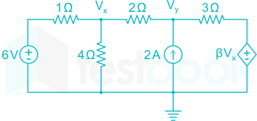
In the given circuit, for voltage Vy to be zero, the value of β should be ______. (Round off to 2 decimal places).

14

Two single-core power cables have total conductor resistance of 0.7 Ω and 0.5 Ω, respectively, and their insulation resistances (between core and sheath) are 600 MΩ and 900 MΩ, respectively. When the two cables are joined in series, the ratio of insulation resistance to conductor resistance is ______ × 106.

15

A 16-bit synchronous binary up-counter is clocked with a frequency fCLK. The two most significant bits are OR-ed together to form an output Y. Measurements show that Y is periodic, and the duration for which Y remains high in each period is 24 ms. The clock frequency fCLK is ______ MHz. (Round off 2 decimal places.)

16

One coulomb of point charge moving with a uniform velocity 10 x^\widehat x m/s enters the region x ≥ 0 having a magnetic flux densityB=(10yx^+10xy^+10z^)T\overrightarrow B = \left( {10y\widehat x + 10x\widehat y + 10\widehat z} \right)T. The magnitude of force on the charge at x = 0+ is ______ N.

(x^{\widehat x}y^{\widehat y} and z^{\widehat z} are unit vectors along x-axis, y-axis, and z-axis, respectively.)

17

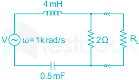
In the given circuit, for maximum power to be delivered to RL, its value should be ______ Ω. (Round off to 2 decimal places.)

18

Inductance is measured by

  1. ((a))

    Kelvin bridge

  2. ((b))

    Wien bridge

  3. ((c))

    Schering bridge

  4. ((d))

    maxwell bridge

Show Answer
Answer: ((d))

maxwell bridge

​Inductance can be measured by Maxwell bridge

Important Points

Type of BridgeName of BridgeUsed to measureImportant
DC BridgesWheatstone bridgeMedium resistance
Corey foster’s bridgeMedium resistance
Kelvin double bridgeVery low resistance
Mega ohm bridgeHigh resistance
MeggerHigh insulation resistanceResistance of cables
AC BridgesMaxwell’s inductance bridgeInductanceNot suitable to measure Q
Maxwell’s inductance capacitance bridgeInductanceSuitable for medium Q coil (1 < Q < 10)
Hay’s bridgeInductanceSuitable for high Q coil (Q > 10), slowest bridge
Anderson’s bridgeInductance5-point bridge, accurate and fastest bridge (Q < 1)
Owen’s bridgeInductanceUsed for measuring low Q coils
Heaviside mutual inductance bridgeMutual inductance
Campbell’s modification of Heaviside bridgeMutual inductance
De-Sauty’s bridgeCapacitanceSuitable for perfect capacitor
Schering bridgeCapacitanceUsed to measure relative permittivity
Wein’s bridgeCapacitance and frequencyHarmonic distortion analyzer, used as a notch filter, used in audio and high-frequency applications
19

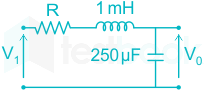
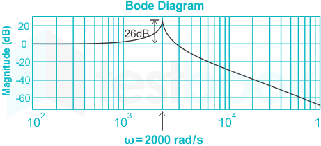
The bode magnitude plot for the transfer function V0(s)Vi(s)\frac{{{V_0}(s)}}{{{V_i}(s)}} of the circuit is as shown. The value of R is ______ Ω. (Round off to 2 decimal places.)

20

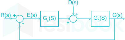
In the given, figure, plant Gp(s)=2.2(1+0.1s)(1+0.4s)(1+1.2s){G_p}(s) = \frac{{2.2}}{{(1 + 0.1s)(1 + 0.4s)(1 + 1.2s)}} and compensator Gc(s)=K(1+T1s1+T2s){G_c}(s) = K\left( {\frac{{1 + {T_1}s}}{{1 + {T_2}s}}} \right). The external disturbance input is D(s). It is desired that when the disturbance is a unit step, the steady-state error should not exceed 0.1 unit. The minimum value of K is ______. (Round off to 2 decimal places.)

21

Let f(x) be a real -valued function such that f'(x0) = 0 for some x0 ∈ (0, 1), and f"(x) > 0 for all x ∈ (0, 1). Then f(x) has

  1. ((a))

    exactly one local minimum in (0, 1)

  2. ((b))

    two distinct local minima in (0, 1)

  3. ((c))

    one local maximum in (0, 1)

  4. ((d))

    no local minimum in (0, 1)

Show Answer
Answer: ((a))

exactly one local minimum in (0, 1)

Concept:

Consider a function y = f(x) on a defined interval of x.

The function attains extreme values (the value can be maximum or minimum or both).

For maxima:

  • Local maxima: A point is the local maxima of a function if there is some other point where the maximum value is greater than the local maxima but that point doesn’t exist nearby local maxima.
  • Global maxima: It is the point where there is no other point has in the domain for which function has more value than global maxima.


For minima:

  • Local minima: A point is the local minima of a function if there is some other point where the minimum value is less than the local minima but that point doesn’t exist nearby local minima.
  • Global minima: It is the point where there is no other point has in the domain for which function has less value than global minima.


Stationary Points: Points where the derivative of the function is zero i.e., f’(x) = 0. The points can be:

  • Inflection point
  • Local maxima
  • Local minima


Second derivative test: Let the function has a stationary point x = a

  • If (d2fdx2)x=a<0{\left( {\frac{{{d^2}f}}{{d{x^2}}}} \right)_{x = a}} < 0  then x = a, is a point of maxima.
  • If (d2fdx2)x=a>0{\left( {\frac{{{d^2}f}}{{d{x^2}}}} \right)_{x = a}} > 0  then x = a, is a point of minima.


Application:

Given f(x) is a real -valued function such that f'(x0) = 0 for some x0 ∈ (0, 1)

Also given f"(x) > 0 for all x ∈ (0, 1)

So, Then f(x) has exactly one local minimum in (0, 1), called the point of minima.

22

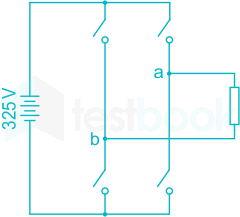
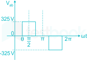
A single-phase full-bridge inverter fed by a 325 V DC produces a symmetric quasi-square waveform across 'ab' as shown. To achieve a modulation index of 0.8, the angle θ expressed in degrees should be ______. (Round off to 2 decimal places.)

(Modulation index is defined as the ratio of the peak of the fundamental component of Vab to the applied DC value.)

23

Consider a power system consisting of N number of buses. Buses in this power system are categorized into slack bus, PV buses and PQ buses for load flow study. The number of PQ buses is NL. The balanced Newton-Raphson method is used to carry out load flow study in polar form. H, S, M, and R are sub-matrices of the Jacobian matrix J as shown below:

\(\left[ {\begin{array}{{20}{c}} {\Delta P}\ {\Delta Q} \end{array}} \right] = J\left[ {\begin{array}{{20}{c}} {\Delta \delta }\ {\Delta V} \end{array}} \right]\) where \(J = \left[ {\begin{array}{*{20}{c}} H&S\ M&R \end{array}} \right]\)

The dimension of the sub-matrix M is

  1. ((a))

    (N - 1) × (N - 1 NL)

  2. ((b))

    NL × (N - 1 + NL)

  3. ((c))

    (N - 1) × (N - 1 + NL)

  4. ((d))

    NL × (N - 1)

Show Answer
Answer: ((d))

NL × (N - 1)

Number of buses in the system = N

Number of PQ buses = NL

Number of slack buses = 1

Number of PV buses = N - 1 - NL

Newton Raphson method for load flow study in polar form

\(\left[ {\begin{array}{{20}{c}} {Δ P}\ {Δ Q} \end{array}} \right] = J\left[ {\begin{array}{{20}{c}} {Δ δ }\ {Δ V} \end{array}} \right]\)

Where \(J = \left[ {\begin{array}{*{20}{c}} H&S\ M&R \end{array}} \right]\)

The submatrix M relates between [ΔQ] and [Δδ]

Number of elements in ΔQ vector = Number of known Q 

Number of elements in ΔQ vector = Number of PQ buses = NL

Number of elements in Δδ vector = Number of unknown δ = N - 1

Size of matrix M = NL × (N - 1)

Size of other sub-matrix:

H = (N - 1) × (N - 1)

S = (N - 1) ×  NL

R = NL × NL

24

Suppose the circles x2 + y2 = 1 and (x - 1)2 + (y - 1)2 = r2 intersect each other orthogonally at the point (u, v). Then u + v = ______.

25

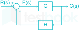
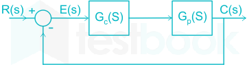
For the closed-loop system shown, the transfer function E(s)R(s)\frac{{E(s)}}{{R(s)}} is

  1. ((a))

    G1+GH\frac{G}{{1 + GH}}

  2. ((b))

    11+GH\frac{1}{{1 + GH}}

  3. ((c))

    11+G\frac{1}{{1 + G}}

  4. ((d))

    GH1+GH\frac{GH}{{1 + GH}}

Show Answer
Answer: ((b))

11+GH\frac{1}{{1 + GH}}

Given:

Forward path gain = G

Feedback path gain = H

Input signal = R(s)

Output signal = C(s)

Error signal = E(s)

C(s) = G × E(s)

Error signal = Input signal - Feedback signal

E(s) = R(s) - H × C(s)

E(s) = R(s) - H × G × E(s)

E(s) + H × G × E(s) = R(s) 

E(s) [1 + GH] = R(s)

E(s)R(s)=1(1+GH){E(s)\over R(s)} = \dfrac{1}{ (1+GH)}

26

Two generators have cost functions F1 and F2. Their incremental-cost characteristics are

dF1dP1=40+0.2P1\frac{{d{F_1}}}{{d{P_1}}} = 40 + 0.2{P_1}

dF2dP2=32+0.4P2\frac{{d{F_2}}}{{d{P_2}}} = 32 + 0.4{P_2}

They need to deliver a combined load of 260 MW. Ignoring network losses, for economic operation, the generations P1 and P2 (in MW) are

  1. ((a))

    P1 = 140, P2 = 120

  2. ((b))

    P1 = 120, P2 = 140

  3. ((c))

    P1 = P2 = 130

  4. ((d))

    P1 = 160, P2 = 100

Show Answer
Answer: ((d))

P1 = 160, P2 = 100

Concept:

Economic distribution of the loads between the units of the power plant:

To determine the economic distribution of a load amongst the different units of a plant, the variable operating costs of each unit must be expressed in terms of its power output.

The fuel cost is the main cost and it must be expressed in Rs./ hour

The fuel cost of a unit can be expressed as

Fi = a Pi2 + b Pi + c Rs / hour

The incremental cost is expressed as

ICi=dFidPi=2aPi+bIC_i = \frac{dF_i}{dP_i} = 2aP_i + b in Rs / MWh or Rs / kWh.

For the economic operation of the system, the incremental cost of each generator must be equal.

Calculation:

Total delivering power is

P1 + P2 = 260 MW .....(1)

The incremental cost of Generator-1 is 

IC1=dF1dP1=40+0.2P1IC_1=\frac{dF_1}{dP_1}=40+0.2P_1

The incremental cost of Generator-2 is 

IC2=dF2dP2=32+0.4P2IC_2=\frac{dF_2}{dP_2}=32+0.4P_2

For the optimum cost, the incremental cost of each generator must be equal.

IC1 = IC2 

⇒ 40 + 0.2 P1 = 32 + 0.4 P2

⇒ 0.2 P1 - 0.4 P2 = - 8 .....(2)

By solving equations (1) and (2), we get

P1 = 160 MW

P2 = 100 MW

27

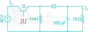
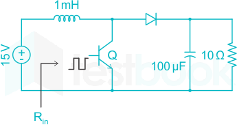
Consider the boost converter shown. Switch Q operating at 25 kHz with a duty cycle of 0.6. Assume the diode and switch to be ideal. Under steady-state condition, the average resistance Rin as seen by source is ______ Ω. (Round off to 2 decimal places.)

28

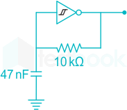
A CMOS Schmitt-trigger inverter has a low output level of 0 V and a high output level of 5 V. It has input thresholds of 1.6 V and 2.4 V. The input capacitance and output resistance of the Schmitt-trigger are negligible. The frequency of the oscillator shown is ______ Hz. (Round off to 2 decimal places.)

29

Consider the table given:

Constructional featureMachine typeMitigation
(P) Damper bars(S) Induction motor(X) Hunting
(Q) Skewed rotor slots(T) Transformer(Y) Magnetic locking
(R) Compensation       winding(U)Synchronous   machine(Z) Armature reaction
(V) DC machine
<br>

The correct combination that relates the constructional feature, machine type and mitigation is

  1. ((a))

    P - V - X, Q - U - Z, R - T - Y

  2. ((b))

    P - U - X, Q - S - Y, R - V - Z

  3. ((c))

    P - T - Y, Q - V - Z, R - S - X

  4. ((d))

    P- U - X, Q - V - Y, R - T - Z

Show Answer
Answer: ((b))

P - U - X, Q - S - Y, R - V - Z

Hunting:

Oscillations of the rotor about its new equilibrium position, due to sudden application or removal of load is called swinging or hunting in the synchronous machine.

Causes for Hunting:

  • Sudden change in load.
  • Sudden change in the supply system or in the field system.
  • Load containing harmonic torque.


Methods for eliminating hunting:

  1. By designing the machine with a suitable synchronizing power coefficient.
  2. By using the flywheel.
  3. By using damper winding.


Damper winding or bars:

  • Damper winding is made with low resistance copper, aluminum, or brass.
  • They are inserted in the slots made under the pole shoes.
  • With respect to damper winding, the rotor behaves like a squirrel cage rotor of an induction motor.


Functions of damper winding:

  1. In alternator to eliminate hunting and to suppress the negative sequence field.
  2. In synchronous motor to eliminate hunting and for starting purpose.


Skewing:

  • ​In the squirrel cage induction motor, the rotor slots in lamination or rotor core are not made parallel to the rotor shaft. A slight angle is maintained between the rotor slots and the rotor shaft due to some operational advantages. This is called rotor skewing.
  • As the rotor slot of the induction motor skewed through some angle so that the bars lie under alternate harmonic poles of the same polarity.​


​The functions of skewed rotor slots in induction motor:

  1. The skewed rotor slot increases the length of the copper bar thereby increases the resistance of the rotor bars hence starting torque of the machine can be improved and also the starting current is drawn by the machine can be reduced.
  2. It makes the air gap flux distribution uniform thereby reduces harmonic torque produced by the machine.
  3. As harmonic torque is reduced, the cogging or magnetic locking phenomenon due to harmonic torque can also be reduced. Here the magnetic locking tendency occurs when rotor teeth remain directly under stator teeth thus they might be magnetically locked.
  4. And we can also eliminate a particular harmonic by selecting a proper skew angle.
  5. The humming noise can be reduced.


Compensating windings:

  • The cross-magnetizing effect of armature reaction may cause trouble in dc machines subjected to large fluctuations in load.
  • In order to neutralize the cross magnetizing effect of the armature reaction, a compensating winding is used. The compensating windings consist of a series of coils embedded in slots in the pole faces. These coils are connected in series with the armature.
  • The series-connected compensating windings produce a magnetic field, which varies directly with armature current. Because the compensating windings are wound to produce a field that opposes the magnetic field of the armature, they tend to cancel the cross magnetizing effect of the armature magnetic field.
30

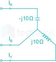
A three-phase balanced voltage is applied to the load shown. The phase sequence is RYB. The ratio IBIR\frac{{\left| {{I_B}} \right|}}{{\left| {{I_R}} \right|}} is ______.

31

Two discrete-time linear time-invariant systems with impulse responses

h1[n] = δ[n - 1] + δ[n + 1] and h2[n] = δ[n] + δ[n - 1] are connected in cascade, where δ[n] is the Kronecker delta. The impulse response of the cascaded system is

  1. ((a))

    δ[n - 1] δ[n] + δ[n + 1] δ[n - 1]

  2. ((b))

    δ[n - 2] + δ[n + 1]

  3. ((c))

    δ[n - 2] + δ[n - 1] + δ[n] + δ[n + 1]

  4. ((d))

    δ[n] δ[n - 1] + δ[n - 2] δ[n + 1]

Show Answer
Answer: ((c))

δ[n - 2] + δ[n - 1] + δ[n] + δ[n + 1]

Concept:

The z-transform of a unit impulse function or Kronecker delta δ [n] ↔ 1

The time-shifting affects the z-transform as:

x[n - n0] = z -n0 X(z)

Application:

Given:

h1[n] = δ[n - 1] + δ[n + 1] 

h2[n] = δ[n] + δ[n - 1] 

If h1[n]and h2[n] are cascaded connected then h[n] = h1[n] * h2[n]

Where '*' denotes convolution.

h[n] = h1[n] * h2[n]

Taking z-transform both side

H[z] = H1[z] ⋅ H2[z]

H[z] = (z-1 + z) ⋅ (1 + z-1) = (z-1 + z-2 + z + 1 )

Taking inverse z-transform both side

h[n] = δ[n-1] + δ[n-2] + δ[n+1] + δ[n]

∴ Impulse response of the cascaded system is δ[n - 2] + δ[n - 1] + δ[n] + δ[n + 1]

32

An 8-pole, 50 Hz, three-phase, slip-ring induction motor has an effective rotor resistance of 0.08 Ω per phase. Its speed at maximum torque is 650 RPM. The additional resistance per phase that must be inserted in the rotor to achieve maximum torque at start is ____________ Ω. (Round off to 2 decimal places.)

Neglect magnetizing current and stator leakage impedance. Consider equivalent circuit parameters referred to stator.

33

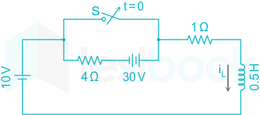
In the circuit, switch 'S' is in the closed position for a very long time. If the switch is opened at time t = 0, then iL (t) in amperes, for t ≥ 0 is

  1. ((a))

    8 + 2e-10t

  2. ((b))

    10

  3. ((c))

    10(1 - e-2t)

  4. ((d))

    8 e-10t

Show Answer
Answer: ((a))

8 + 2e-10t

Concept:

The current through the inductor in transient is given by:

i(t)=i()+(i(0)i())etRLi\left( t \right) = i(\infty ) + \left( {i\left( 0 \right) - i\left( ∞ \right)} \right){e^{ - \frac{{tR}}{L}}} ....(1)

i(∞) = Steady-state/final value of the inductor

i(0) = Initial stored current

Also, an inductor does not allow a sudden change in voltage, i.e.

i(0-) = i(0+)

τ = Time Constant

The time constant in the RL series circuit is given by:

τ=LRτ=\dfrac{L}{R}

Calculation:

For t < 0:

Initially, for t < 0, the switch is closed for a long time.

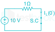
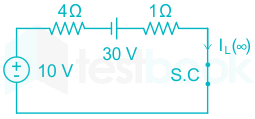
The 4 Ω resistor and 30 V source are bypassed and the inductor is short-circuited.

Current flowing in the circuit will be:

iL(0)=101=10 Ai_L(0^-)=\dfrac{10}{1}=10~A

For t > 0:

After an infinite time when the switch is closed, the inductor is short-circuited and the current will be:

iL()=10+304+1=8 Ai_L(\infty)=\dfrac{10+30}{4+1}=8~A

τ = L/R

τ=125=110\rm \tau = \frac{{\frac{1}{2}}}{5} = \frac{1}{{10}}

From equation (1)

iL(t) = 8 + [10 - 8] e-10t

iL(t) = 8 + 2e-10t

34

In the open interval (0, 1), the polynomial p(x) = x4 - 4x3 + 2 has

  1. ((a))

    one real root

  2. ((b))

    three real roots

  3. ((c))

    two real roots

  4. ((d))

    no real roots

Show Answer
Answer: ((a))

one real root

Concept:

Intermediate Value Theorem:

It states that if 'f' is a continuous function whose domain contains the interval [a, b], then it takes any given value between f(a) and f(b) at some point within the interval.

Considerd an interval of I = [a, b], and a continuous function f(x) then,

If 'u' is the number between f(a) and, f(b), then

min[f(a),;f(b)]<u<max[f(a),f(b)]\min \left[ {f\left( a \right),;f\left( b \right)} \right] < u < \max \left[ {f\left( a \right),f\left( b \right)} \right]

c(a,b);and,;f(c)=uc \in \left( {a,b} \right);and,;f\left( c \right) = u

Calculation:

Given polynomial,

p(x) = x4 - 4x3 + 2

Using intermediate value theorem,

p(0) = 0 - 0 + 2 = 2

p(1) = 1 - 4 + 2 = -1

Since,

p(0) > 0 .... (1)

p(1) < 0 .... (2)

From equation (1) and (2), there exist a value 'x' in between 0 and 1 where,

p(x) = 0

Hence, in the open interval (0, 1), the polynomial p(x) has one real root.

35

A belt-driven DC shunt generator running at 300 RPM delivers 100 kW to a 200 V DC grid. It continues to run as a motor when the belt breaks, taking 10 kW from the DC grid. The armature resistance is 0.025 Ω, field resistance is 50 Ω, and brush drop is 2 V. Ignoring armature reaction, the speed of the motor is ____________ RPM. (Round off to 2 decimal places.)

36

A signal generator having a source resistance of 50 Ω is set to generate a 1 kHz sinewave. Open circuit terminal voltage is 10 V peak-to-peak. Connecting a capacitor across the terminals reduces the voltage to 8 V peak-to-peak. The value of this capacitor is __________ μF. (Round off to 2 decimal places.)

37

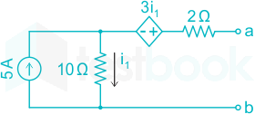
For the network shown, the equivalent Thevenin voltage and Thevenin impedance as seen across terminals 'ab' is

  1. ((a))

    35 V in series with 2 Ω

  2. ((b))

    10 V in series with 12 Ω

  3. ((c))

    65 V in series with 15 Ω

  4. ((d))

    50 V in series with 2 Ω

Show Answer
Answer: ((c))

65 V in series with 15 Ω

Concept:

Thevenin’s Theorem:

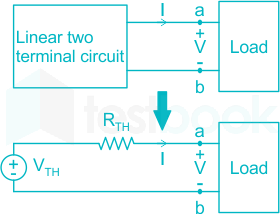
Thevenin’s theorem states that a linear-bilateral two-terminal circuit can be replaced by an equivalent circuit consisting of a voltage source Vth in series with a resistor Rth.

Where Vth is the open-circuit voltage at the terminals and Rth is the input or equivalent resistance at the terminals when the independent sources are turned off.


Different case of Thevenin's theorem:

Case 1: Circuit with only dependent source,

In this case, Rth is finding by the voltage test method

And, Vth = 0

Case 2: Circuit with both dependent source and independent source,

In this case, Rth is finding by the voltage test method

And, Vth is finding by the same method above discuss.

Calculation:

Given circuit,

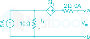
Step 1: Finding Vth across terminal ab,

Vth = V10Ω + 3i1

5 A = i1 + 0

∴ i1 = 5 A

Vth = 10(5) + 3(5) = 65 volt

Step 2: Finding Rth across terminal ab,

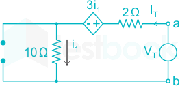
To finding Rth we have to open-circuited the current source by its internal resistance and applied test voltage across the terminal ab,

Rth=VTIT{R_{th}} = \frac{{{V_T}}}{{{I_T}}}

IT = i1

VT = 13i1 + 2i1 = 15IT

Rth=VTIT=151=15Ω{R_{th}} = \frac{{{V_T}}}{{{I_T}}} = \frac{{15}}{1} = 15\Omega

38

Consider the buck-boost converter shown. Switch Q is operating at 25 kHz and 0.75 duty-cycle. Assume diode and switch to be ideal. Under the steady-state condition, the average current flowing through the inductor is __________ A.

39

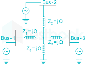
A 3-Bus network is shown. Consider generators as ideal voltage sources. If rows 1, 2 and 3 of the YBus matrix correspond to Bus 1, 2 and 3, respectively, then YBus of the network is

  1. ((a))

    \(\left[ \begin{array}{20 {c*}} {-\frac 3 4 j}&{\frac 1 4 j}&{\frac 1 4 j}\\ {\frac 1 4 j}&{-\frac 3 4 j}&{\frac 1 4j}\\ {\frac 1 4 j}&{\frac 1 4 j}&{-\frac 3 4 j} \end{array} \right]\)

  2. ((b))

    \(\left[ \begin{array}{20 {c*}} {-4j}&{2j}&{2j}\\ {2j}&{-4j}&{2j}\\ {2j}&{2j}&{-4j} \end{array} \right]\)

  3. ((c))

    \(\left[ \begin{array}{20 {c*}} {-\frac 1 2j}&{\frac 1 4j}&{\frac 1 4j}\\ {\frac 1 4j}&{-\frac 1 2j}&{\frac 1 4j}\\ {\frac 1 4j}&{\frac 1 4j}&{-\frac 1 2j} \end{array} \right]\)

  4. ((d))

    \(\left[ \begin{array}{20 {c*}} {-4j}&{j}&{j}\\ {j}&{-4j}&{j}\\ {j}&{j}&{-4j} \end{array} \right]\)

Show Answer
Answer: ((a))

\(\left[ \begin{array}{20 {c*}} {-\frac 3 4 j}&{\frac 1 4 j}&{\frac 1 4 j}\\ {\frac 1 4 j}&{-\frac 3 4 j}&{\frac 1 4j}\\ {\frac 1 4 j}&{\frac 1 4 j}&{-\frac 3 4 j} \end{array} \right]\)

Concept:

Bus Admittance Matrix (YBus):

Consider a small power system network consisting of two generating stations, three transmission lines, one load, and a static capacitor connected to load bus 3.

Assumed that the network is symmetrical and operating under the balance conditions.
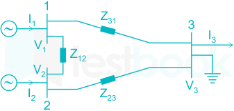
The node voltage equation of the system can be written as,

I1=(y12+y31)V1y12V2y31V3{I_1} = \left( {{y_{12}} + {y_{31}}} \right){V_1} - {y_{12}}{V_2} - {y_{31}}{V_3}

I2=y12V1+(y12+y23)V2y23V3{I_2} = - {y_{12}}{V_1} + \left( {{y_{12}} + {y_{23}}} \right){V_2} - {y_{23}}{V_3}

I3=y31V1y23V2+(y31+y23+y30)V3 - {I_3} = - {y_{31}}{V_1} - {y_{23}}{V_2} + \left( {{y_{31}} + {y_{23}} + {y_{30}}} \right){V_3}

Where,

y12=1z12,;y23=1z23,;y31=1z31{y_{12}} = \frac{1}{{{z_{12}}}},;{y_{23}} = \frac{1}{{{z_{23}}}},;{y_{31}} = \frac{1}{{{z_{31}}}}

The above equation can be written in form of a matrix,

\(\left[ {\begin{array}{{20}{c}} {{I_1}}\ {{I_2}}\ { - {I_3}} \end{array}} \right] = \left[ {\begin{array}{{20}{c}} {{y_{12}} + {y_{31}}}&{ - {y_{12}}}&{ - {y_{31}}}\ { - {y_{12}}}&{{y_{12}} + {y_{23}}}&{ - {y_{23}}}\ { - {y_{31}}}&{ - {y_{23}}}&{{y_{31}} + {y_{23}} + {y_{30}}} \end{array}} \right]\left[ {\begin{array}{*{20}{c}} {{V_1}}\ {{V_2}}\ {{V_3}} \end{array}} \right]\)

\(\left[ {\begin{array}{{20}{c}} {{I_1}}\ {{I_2}}\ { - {I_3}} \end{array}} \right] = \left[ {\begin{array}{{20}{c}} {{Y_{11}}}&{{Y_{12}}}&{{Y_{13}}}\ {{Y_{21}}}&{{Y_{22}}}&{{Y_{23}}}\ {{Y_{31}}}&{{Y_{32}}}&{{Y_{33}}} \end{array}} \right]\left[ {\begin{array}{*{20}{c}} {{V_1}}\ {{V_2}}\ {{V_3}} \end{array}} \right]\)

Where,

Y11 = y12 + y31, Y22 = y21 + y23, Y33 = y30 + y31 + y32

Y12 = Y21 = - y12, Y23 = Y32 = -y23, Y31 = Y13 = -y31

The element Y11, Y22, Y33 is termed as self admittances.

The elements Y12, Y13, Y21, Y23, Y31, Y32 termed as mutual admittance.

Calculation:

Given circuit can be drawn as,
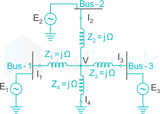
Applying KCL at node V,

I1 + I2 + I3 + I4 = 0

E1Vj1+E2Vj1+E3Vj1+Vj1=0\frac{{{E_1} - V}}{{j1}} + \frac{{{E_2} - V}}{{j1}} + \frac{{{E_3} - V}}{{j1}} + \frac{{ - V}}{{j1}} = 0

4V = E1 + E2 + E3

I1=E1Vj1=E1(E1+E2+E34)j1{I_1} = \frac{{{E_1} - V}}{{j1}} = \frac{{{E_1} - \left( {\frac{{{E_1} + {E_2} + {E_3}}}{4}} \right)}}{{j1}}

I1=j34E1+j14E2+j14E3{I_1} = j\frac{{ - 3}}{4}{E_1} + j\frac{1}{4}{E_2} + j\frac{1}{4}{E_3}

I2=E2Vj1=E2(E1+E2+E34)j1{I_2} = \frac{{{E_2} - V}}{{j1}} = \frac{{{E_2} - \left( {\frac{{{E_1} + {E_2} + {E_3}}}{4}} \right)}}{{j1}}

I2=j14E1+j34E2+j14E3{I_2} = j\frac{1}{4}{E_1} + j\frac{{ - 3}}{4}{E_2} + j\frac{1}{4}{E_3}

I3=E3Vj1=E3(E1+E2+E34)j1{I_3} = \frac{{{E_3} - V}}{{j1}} = \frac{{{E_3} - \left( {\frac{{{E_1} + {E_2} + {E_3}}}{4}} \right)}}{{j1}}

I1=j14E1+j14E2+j34E3{I_1} = j\frac{1}{4}{E_1} + j\frac{1}{4}{E_2} + j\frac{{ - 3}}{4}{E_3}

The equation of current can be written in form of the matrix,

\(\left[ {\begin{array}{{20}{c}} {{I_1}}\ {{I_2}}\ {{I_3}} \end{array}} \right] = j\left[ {\begin{array}{{20}{c}} {\frac{{ - 3}}{4}}&{\frac{1}{4}}&{\frac{1}{4}}\ {\frac{1}{4}}&{\frac{{ - 3}}{4}}&{\frac{1}{4}}\ {\frac{1}{4}}&{\frac{1}{4}}&{\frac{{ - 3}}{4}} \end{array}} \right]\left[ {\begin{array}{*{20}{c}} {{E_1}}\ {{E_2}}\ {{E_3}} \end{array}} \right]\)

\({Y_{bus}} = j\left[ {\begin{array}{*{20}{c}} {\frac{{ - 3}}{4}}&{\frac{1}{4}}&{\frac{1}{4}}\ {\frac{1}{4}}&{\frac{{ - 3}}{4}}&{\frac{1}{4}}\ {\frac{1}{4}}&{\frac{1}{4}}&{\frac{{ - 3}}{4}} \end{array}} \right]\)

\(Y_{bus}=\left[ \begin{array}{20 {c*}} {-\frac 3 4 j}&{\frac 1 4 j}&{\frac 1 4 j}\\ {\frac 1 4 j}&{-\frac 3 4 j}&{\frac 1 4j}\\ {\frac 1 4 j}&{\frac 1 4 j}&{-\frac 3 4 j} \end{array} \right]\)
40

Consider a closed-loop system as shown. Gp(s)=14.4s(1+0.1s)G_p(s) = \frac {14.4}{s(1 + 0.1s)} is the plant transfer function and Gc(s) = 1 is the compensator. For a unit-step input, the output response has damped oscillations. The damped natural frequency is __________ rad / s. (Round off to 2 decimal places.)

41

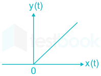
If the input x(t) and output y(t) of a system are related as y(t) = max (0, x(t)), then the system is

  1. ((a))

    linear and time-invariant

  2. ((b))

    linear and time-variant

  3. ((c))

    non-linear and time-variant

  4. ((d))

    non-linear and time-invariant

Show Answer
Answer: ((d))

non-linear and time-invariant

Concept:

Linearity: Necessary and sufficient condition to prove the linearity of the system is that the linear system follows the laws of superposition i.e. the response of the system is the sum of the responses obtained from each input considered separately.

y{ax1[t] + bx2[t]} = a y{x1[t]} + b y{x2[t]}

Conditions to check whether the system is linear or not.

  • The output should be zero for zero input.
  • There should not be any non-linear operator present in the system.


Time-Invariance: If the input to a time-invariant system is shifted in time, its output remains the same signal, but is shifted equally in time.

If the output for an input x(t) is y(t), then a time shift of t0 in the input gives the t0 shift in the output.

x(t) → y(t), then x(t – t0) → y(t – t0)

Application:

Given y(t) = max (0, x(t))

\(y(t)= \left{ {\begin{array}{*{20}{c}} {0,;;;;x(t) < 0}\ {x(t),x(t) > 0} \end{array}} \right.\)

Linearity checking:

For input x1(t) = -1 , Output y1(t) = 0

For input x2(t) = 1 , Output y2(t) = 1

y(x1(t) + x2(t)) = y(-1 + 1) = y(0) = 0

y1(t) + y2(t) = 0 + 1 = 1

⇒ y(x1(t) + x2(t)) ≠ y1(t) + y2(t)

Hence the system is non linear.

Time-invariance checking:

Let the output is delayed by to

\(y(t-t_o)= \left{ {\begin{array}{*{20}{c}} {0,;;;;;;;;;;;x(t-t_o) < 0}\ {x(t-t_o),x(t-t_o) > 0} \end{array}} \right.\)

Let the output of the system be g(t) for a delayed input x(t - to)

\(y_1(t)= \left{ {\begin{array}{{20}{c}} {0,;;;;g(t) < 0}\ {g(t),g(t) > 0} \end{array}} \right.\;\= \left{ {\begin{array}{{20}{c}} {0,;;;;;;;;;;;x(t-t_o) < 0}\ {x(t-t_o),x(t-t_o) > 0} \end{array}} \right.\;\=y(t-t_o)\)

Hence, the given system is time-invariant

42

Consider a large parallel plate capacitor. The gap d between the two plates is filled entirely with a dielectric slab of relative permittivity 5. The plates are initially charged to a potential difference of V volts and then disconnected from the source. If the dielectric slab is pulled out completely, then the ratio of the new electric field E2 in the gap to the original electric field E1 is ___________.

43

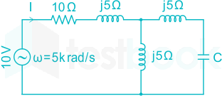
In the given circuit, the value of capacitor C that makes current I = 0 is ____________ μF.

44

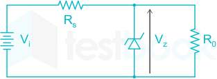
In the circuit shown, a 5 V Zener diode is used to regulate the voltage across load R0. The input is an unregulated DC voltage with a minimum value of 6 V and a maximum value of 8 V. The value of RS is 6 Ω. The Zener diode has a maximum rated power dissipation of 2.5 W. Assuming the Zener diode to be ideal, the minimum value of R0 is _________ Ω.

45

A 1 μC point charge is held at the origin of a cartesian coordinate system. If a second point charge of 10 μC is moved from (0, 10, 0) to (5, 5, 5) and subsequently to (5, 0, 0), then the total work done is _________ mJ.

(Round off to 2 decimal places).

Take 14πεo=9×10⁹\frac {1}{4\pi \varepsilon_o} = 9 \times 10^9 in SI units. All coordinates are in meters.

46

Let p and q be real numbers such that p2 + q2 = 1. The eigenvalues of the matrix [pqqp]\begin{bmatrix} p & q \\ q & -p \end{bmatrix} are

  1. ((a))

    pq and -pq

  2. ((b))

    1 and -1

  3. ((c))

    1 and 1

  4. ((d))

    j and -j

Show Answer
Answer: ((b))

1 and -1

Concept:

Matrix:

  • If A is any square matrix of order n, we can form the matrix [A – λI], where I is the nth order unit matrix.
  • The determinant of this matrix equated to zero i.e. |A – λI| = 0 is called the characteristic equation of A.
  • The roots of the characteristic equation are called Eigenvalues or latent roots or characteristic roots of matrix A.


Properties of Eigenvalues:

  • The sum of Eigenvalues of a matrix A is equal to the trace of that matrix A
  • The product of Eigenvalues of a matrix A is equal to the determinant of that matrix A


Calculation:

Given:

p2 + q2 = 1

Let \(A = \left[ {\begin{array}{*{20}{c}} p&{ q}\ { q}&-p \end{array}} \right]\)
|A – λI| = 0

\( \Rightarrow \left| {\begin{array}{*{20}{c}} {p - λ }&{ q}\ { q}&{-p - λ } \end{array}} \right| = 0\)

⇒ (p - λ)(- p - λ) - q2 = 0

⇒ - p2 - pλ + pλ + λ2 - q2 = 0

⇒ λ2 - 1 = 0

⇒ λ = ± 1


Let the Eigenvalues be a, b

Determinant of matrix = -p2 - q2 = - 1 

Product of Eigenvalues = a × b = -1 

Checking from the given option

⇒ a = 1, b = - 1.

47

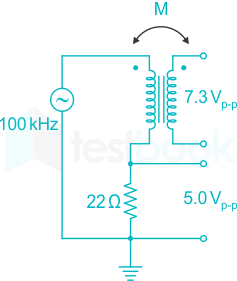
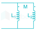
An air-core radio-frequency transformer as shown has a primary winding and a secondary winding. The mutual inductance M between the windings of the transformer is ______ μH.

(Round off to 2 decimal places.)

48

Consider a continuous-time signal x(t) defined by x(t) = 0 for |t| > 1, and x(t) = 1 - |t| for |t| ≤ 1. Let the Fourier transform of x(t) be defined as X(ω)=x(t)ejωtdtX(ω)=\displaystyle\int_{-\infty}^\infty x(t) e^{-jω t}dt. The maximum magnitude of X(ω) is _____

49

Let (-1 - j), (3 - j), (3 + j) and (-1 + j) be the vertices of a rectangle C in the complex plane. Assuming that C is traversed in counter-clockwise direction, the value of the countour integral Cdzz2(z4)\displaystyle\oint_C \dfrac{dz}{z^2 (z-4)} is

  1. ((a))

    0

  2. ((b))

    jπ/16 

  3. ((c))

    jπ/2 

  4. ((d))

    -jπ/8 

Show Answer
Answer: ((d))

-jπ/8 

Concept:

Residue Theorem: 

If f(z) is analytic in a closed curve C except at a finite number of singular points within C, then

cf(z) dz = 2πj × [sum of residues at the singular points within C]

Formula to find residue:

  1. If f(z) has a simple pole at z = a, then

Res;f(a)=limza[(za)f(z)]Res;f\left( a \right) = \mathop {\lim }\limits_{z \to a} \left[ {\left( {z - a} \right)f\left( z \right)} \right]

  1. If f(z) has a pole of order n at z = a, then

\(Res;f\left( a \right) = \frac{1}{{\left( {n - 1} \right)!}}{\left{ {\frac{{{d^{n - 1}}}}{{d{z^{n - 1}}}}\left[ {{{\left( {z - a} \right)}^n}f\left( z \right)} \right]} \right}_{z = a}}\)

Application:

Given (-1 - j), (3 - j), (3 + j) and (-1 + j) are the vertices of a rectangle C in the complex plane

f(z) from the given data is,

f(z)=1z2(z4)f(z)=\dfrac{1}{z^2 (z-4)}

Poleas of f(z) is

z = 0 of order n = 2, lies in side the closed curve.

z = 4 of order n = 1, lies outside the closed curve.

∴ Cdzz2(z4)=2πj;Res;f(0)\displaystyle\oint_C \dfrac{dz}{z^2 (z-4)}=2π j;Res;f\left( 0 \right)  

⇒ \(Res;f\left( 0 \right) = \frac{1}{{\left( {2 - 1} \right)!}}{\left{ {\frac{{{d^{2 - 1}}}}{{d{z^{2 - 1}}}}\left[ {{{\left( {z } \right)}^2}\dfrac{1}{z^2 (z-4)}} \right]} \right}_{z = 0}}\)

Res;f(0)=ddz[1z4]z=0=116Res;f(0)=\dfrac{d}{dz}\left[\dfrac{1}{z-4}\right]_{z=0}=-\dfrac{1}{16}

Cdzz2(z4)=2πj(116)=jπ8\displaystyle\oint_C \dfrac{dz}{z^2 (z-4)}=2π j\left(\dfrac{-1}{16}\right)=\dfrac{-jπ }{8}

Additional Information

Cauchy’s Theorem:

If f(z) is an analytic function and f’(z) is continuous at each point within and on a closed curve C, then

Cf(z)dz=0\mathop \oint \limits_C f\left( z \right)dz = 0

Cauchy’s Integral Formula:

If f(z) is an analytic function within a closed curve and if a is any point within C, then

f(a)=12πiCf(z)zadzf\left( a \right) = \frac{1}{{2\pi i}}\mathop \oint \limits_C \frac{{f\left( z \right)}}{{z - a}}dz

fn(a)=n!2πiCf(z)(za)n+1dz{f^n}\left( a \right) = \frac{{n!}}{{2\pi i}}\mathop \oint \limits_C \frac{{f\left( z \right)}}{{{{\left( {z - a} \right)}^{n + 1}}}}dz

50

The state space representation of a first-order system is given as 

ẋ = -x + u

y = x

Where, x is the state variable, u is the control input and y is the controlled output. Let u = -K.x be the control law, where K is the controller gain. To place a closed-loop pole at -2, the value of K is ______

51

A 100 Hz square wave, switching between 0 V and 5 V, is applied to a CR high-pass filter circuit as shown. The output voltage waveform across the resistor is 6.2 V peak-to-peak. If the resistance R is 820 Ω, then the value C is ______ μF.

(Round off to 2 decimal places)

52

An alternator with internal voltage of 1∠δ1 p.u. and synchronous reactance of 0.4 p.u. is connected by a transmission line of reactance 0.1 p.u. to a synchronous motor having synchronous reactance 0.35 p.u. and internal voltage of 0.85 ∠δ2 p.u. If the real power supplied by the alternator is 0.866 p.u., then (δ1 - δ2) is _____ degrees. (Round off to 2 decimal places.)

(Machines are of non-salient type. Neglect resistances)

53

Let A be a 10 × 10 matrix such that A5 is a null matrix, and let I be the 10 × 10 identity matrix. The determinant of A + I is ______.

54

The power input to a 500 V, 50 Hz, 6-pole, 3-phase induction motor running at 975 RPM is 40 kW. The total stator losses are 1 kW. If the total friction and windage losses are 2.025 kW, then the efficiency is _____%

55

The causal signal with z-transform z2 (z - a)-2 is

(u[n] is the unit step signal)

  1. ((a))

    (n + 1) an u[n]

  2. ((b))

    a2n u[n]

  3. ((c))

    n-1 an u[n]

  4. ((d))

    n2 an u[n]

Show Answer
Answer: ((a))

(n + 1) an u[n]

Concept:

Causal Signals:

  • Causal Signals are signals that are zero for all negative time.
  • Causality in a system determines whether a system relies on future information of a signal x [n+1].
  • Talking about “causality” in signals, it means whether they are zero to the left of t = 0 or zero to the right of t = 0.
  • A causal signal is zero for t < 0.
  • A system is said to be causal if its output depends upon present and past inputs, and does not depend upon future input.


Calculation:

Given a casual signal,

X (Z) = z2 (z - a)-2

X(Z)=z2(az)2X(Z) = \frac{{{z^2}}}{{{{\left( {a - z} \right)}^2}}}

From standard Z-Transform,

n(a)nu(n)az(za)2n{\left( a \right)^n}u\left( n \right) \leftrightarrow \frac{{az}}{{{{\left( {z - a} \right)}^2}}}

n(a)n1u(n)z(za)2n{\left( a \right)^{n - 1}}u\left( n \right) \leftrightarrow \frac{z}{{{{\left( {z - a} \right)}^2}}}

From the time-shifting property,

x(nn0)zn0X(z)x\left( {n - {n_0}} \right) \leftrightarrow {z^{ - {n_0}}}X\left( z \right)

(n+1)(a)n+11u(n+1)z[z(za)2]\left( {n + 1} \right){\left( a \right)^{n + 1 - 1}}u\left( {n + 1} \right) \leftrightarrow z\left[ {\frac{z}{{{{\left( {z - a} \right)}^2}}}} \right]

(n+1)(a)nu(n+1)z2(za)2\left( {n + 1} \right){\left( a \right)^n}u\left( {n + 1} \right) \leftrightarrow \frac{{{z^2}}}{{{{\left( {z - a} \right)}^2}}}

Since,

X(z)=z2(za)2X\left( z \right) = \frac{{{z^2}}}{{{{\left( {z - a} \right)}^2}}}

Therefore,

x(n)=(n+1)(a)nu(n+1)x\left( n \right) = \left( {n + 1} \right){\left( a \right)^n}u\left( {n + 1} \right)

The given signal is causal, therefore,

x(n)=(n+1)(a)nu(n)x\left( n \right) = \left( {n + 1} \right){\left( a \right)^n}u\left( n \right)

Important Points

Z-Transform basic functions:

SequenceZ-Transform
δ (n)1
u (n)zz1\frac{z}{{z - 1}}
anzza\frac{z}{{z - a}}
n (an) u (n)az(az)2\frac{{az}}{{{{\left( {a - z} \right)}^2}}}
n (an - 1) u (n)z(az)2\frac{z}{{{{\left( {a - z} \right)}^2}}}
n (an - 1) u (n - 1)1za\frac{1}{{z - a}}
56

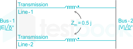
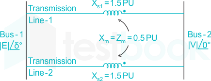
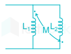
In the figure shown, self-impedances of the two transmission lines are 1.5j p.u. each, and Zm = 0.5j p.u. is the mutual impedance. Bus voltages shown in the figure are in p.u. Given that δ > 0, the maximum steady-state real power that can be transferred in p.u. from Bus-1 to Bus-2 is


  1. ((a))

    |E| |V|

  2. ((b))

    2 |E| |V|

  3. ((c))

    EV2\dfrac{|E||V|}{2}

  4. ((d))

    3EV2\dfrac{3|E||V|}{2}

Show Answer
Answer: ((a))

|E| |V|

Concept: 

Power Transmission Capability of Synchronous Generator:

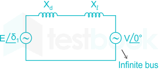
Considered a synchronous generator connected to the infinite bus through a transmission line of reactance Xl.

Assumed that the resistance and capacitance of the system are zero.

Where,

V = V∠0 = voltage at infinite bus

E = E∠δ = voltage behind direct axis synchronous reactance of the generator

Xd = synchronous or transient reactance of machine

Xl = line reactance

Complex power delivered by the generator to the system is,

\(S = V{I^} = V{\left[ {\frac{{E\angle {δ _;} - V}}{{j\left( {{X_d} + {X_l}} \right)}}} \right]^}\)

Let, X = Xd + Xl

Active power transferred to the system,

P=EVXsinδP = \frac{{EV}}{X}sinδ

The maximum steady-state power transfer occurs when,

δ = 90°

Reactive power transferred to the system,

Q=(EVXcosδV2X)Q = \left( {\frac{{EV}}{X}cosδ - \frac{{{V^2}}}{X}} \right)

Calculation:

Given,

Xs1 = Xs2 = j1.5 p.u.

Xm = j0.5 p.u.

Equivalent reactance (X) will be written as,

X=Xs1Xs2Xm2Xs1+Xs22XmX = \frac{{{X_{s1}}{X_{s2}} - X_m^2}}{{{X_{s1}} + {X_{s2}} - 2{X_m}}}

L1L2M2L1+L22M\frac{{{L_1}{L_2} - {M^2}}}{{{L_1} + {L_2} - 2M}}

From the above concept, 

The maximum steady-state power transfer occurs when δ = 90°

Pm=EVX=EVj1=EV{P_m} = \frac{{\left| E \right|\left| V \right|}}{X} = \frac{{\left| E \right|\left| V \right|}}{{j1}} = \left| E \right|\left| V \right|

Important Points

The equivalent inductance of parallel aiding connection is

Leq = L1L2M2L1+L22M\frac{{{L_1}{L_2} - {M^2}}}{{{L_1} + {L_2} - 2M}}

The equivalent inductance of parallel opposing connection is

Leq = L1L2M2L1+L2+2M\frac{{{L_1}{L_2} - {M^2}}}{{{L_1} + {L_2} + 2M}}

57

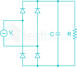
In the circuit shown, the input Vi is a sinusoidal AC voltage having an RMS value of 230 V ± 20%. The worst-case peak-inverse voltage seen across any diode is ______V. (Round off to 2 decimal places).

58

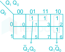
A counter is constructed with three D flip-flops. The input-output pairs are named (D0, Q0), (D1, Q1), and (D2, Q2), where the subscript 0 denotes the least significant bit. The output sequence is desired to be the Gray-code sequence 000, 001, 011, 010, 110, 111, 101, and 100, repeating periodically. Note that the bits are listed in the Q2 Q1 Q0 format. The combinational logic expression for D1 is

  1. ((a))

    Q2 Q0 + Q10

  2. ((b))

    Q2 Q1 + Q̅21

  3. ((c))

    Q2 Q1 Q0

  4. ((d))

    2 Q0 + Q10

Show Answer
Answer: ((d))

2 Q0 + Q10

Concept:

Excitation Table / Transition Table:

D Flip-Flop:

The single input is called the 'DATA' input. If this data input is held HIGH, the flip flop would be 'SET' and when it is LOW the flip flop would change and become 'RESET'.

Present State QNext State Q+D
000
011
100
111


Application:

Given:

000 → 001 → 011 → 010 → 110 → 111 → 101 → 100 → 000 ⋅⋅⋅⋅⋅⋅⋅⋅⋅⋅⋅⋅

Table for the given condition will be

Present StateNext StateD2D1D0
Q2Q1Q0Q2+Q1+Q0+
000001001
001011011
011010010
010110110
110111111
111101101
101100100
100000000


D1 will have high logic at (1,3,2,6) ⇒ D1 = ∑m (1,3,2,6)

∴ D1 = Q̅Q0 + Q0

59

In a single-phase transformer, the total iron loss is 2500 W at nominal voltage of 440 V and frequency 50 Hz. The total iron loss is 850 W at 220 V and 25 Hz. Then, at nominal voltage and frequency, the hysteresis loss and eddy current loss respectively are

  1. ((a))

    1600 W and 900 W

  2. ((b))

    900 W and 1600 W

  3. ((c))

    600 W and 250 W

  4. ((d))

    250 W and 600 W

Show Answer
Answer: ((b))

900 W and 1600 W

Concept:

Separation of Iron loss in Transformer:

In transformer iron loss (Pi) has two components namely Hysteresis loss (Ph) and Eddy current loss (Pe).

Pi = Ph + Pe

Pi=khfBmn+kef2Bm2{P_i} = {k_h}fB_m^n + {k_e}{f^2}B_m^2  …. (1)

Where,

Kh and ke are loss coefficient constant and their value depends on the type of material

Bm is the maximum value of flux density

f is supply frequency

Phf{P_h} \propto f

Ph=af{P_h} = af

Pef2{P_e} \propto {f^2}

Pe=bf2{P_e} = b{f^2}

Where a and b are constants.

Pi=af+bf2{P_i} = af + b{f^2}

Pif=a+bf\frac{{{P_i}}}{f} = a + bf

Note: For the separation of these two losses, the no-load test is performed on the transformer.

Calculation:

Given,

V1 = 440 V

f1 = 50 Hz

V2 = 220 V

f2 = 25 Hz

V1f1=V2f2=8.8\frac{{{V_1}}}{{{f_1}}} = \frac{{{V_2}}}{{{f_2}}} = 8.8

Hence, (V / f) ratio is constant,

P1 = 2500 W

P2 = 850 W

From the above concept,

Pi = af + bf2

2500 = 50a + 2500b .... (1)

850 = 25a + 625b .... (2)

From equation (1) and (2),

a = 18 and b = 0.64

Iron loss at 50 Hz,

Hysteresis loss (Ph) = af = 18 × 50 = 900 W

Eddy current loss (Pe) = bf2 = 0.64 × 2500 = 1600 W

60

Let f(t) be an even function i.e. f(-t) = f(t) for all t. Let the Fourier transform of f(t) be defined as F(ω)=f(t)ejωtdtF(ω ) = \displaystyle\int_{-\infty}^\infty f(t) e^{-jω t}dt. Suppose dF(ω)dω=ωF(ω)\dfrac{dF(ω)}{dω} = -ω F(ω) for all ω, and F(0) = 1. Then

  1. ((a))

    f(0) < 1

  2. ((b))

    f(0) = 1

  3. ((c))

    f(0) = 0

  4. ((d))

    f(0) > 1

Show Answer
Answer: ((a))

f(0) < 1

Concept:

Even Signal:

A signal f(t) is called even signal if, 𝑓(𝑡) = 𝑓(−𝑡)

It is given by,

\({f_e}\left( t \right) = 2\mathop \smallint \limits_0^{\frac{T}{2}} {f_e}\left( t \right)dt \)

Differentiation and Integration Properties of Fourier transform:

If,

x(t)F.TX(ω)x\left( t \right)\mathop \leftrightarrow \limits^{F.T} X\left( \omega \right)

Then differentiation property states that,

dx(t)dtF.TjωX(ω)\frac{{dx\left( t \right)}}{{dt}}\mathop \leftrightarrow \limits^{F.T} j\omega X\left( \omega \right)

dnx(t)dtnF.T(jω)nX(ω)\frac{{{d^n}x\left( t \right)}}{{d{t^n}}}\mathop \leftrightarrow \limits^{F.T} {\left( {j\omega } \right)^n}X\left( \omega \right)

Then integration property states that,

x(t)dtF.T1jωX(ω)\smallint x\left( t \right)dt\mathop \leftrightarrow \limits^{F.T} \frac{1}{{j\omega }}X\left( \omega \right)

x(t)dtF.T1(jω)nX(ω)\smallint \smallint \smallint \ldots \smallint x\left( t \right)dt\mathop \leftrightarrow \limits^{F.T} \frac{1}{{{{\left( {j\omega } \right)}^n}}}X\left( \omega \right)

Calculation:

Given function is even,

dF(ω)dω=ωF(ω)\dfrac{dF(ω)}{dω} = -ω F(ω) .... (1)

From differentiation property,

tf(t)=jdF(ω)dωtf\left( t \right) = \frac{{jdF\left( \omega \right)}}{{d\omega }}

Applying IFT to the above equation,

jtf(t)=jdf(t)df - jtf\left( t \right) = \frac{{jdf\left( t \right)}}{{df}}

df(t)dt=tf(t)\frac{{df\left( t \right)}}{{dt}} = - tf\left( t \right) .... (2)

From equation (1) and (2) it is clear that the f (t) is the change of Gaussian function, it can be written as,

f(t)=12πet22f\left( t \right) = \frac{1}{{\sqrt {2\pi } }}{e^{\frac{{ - {t^2}}}{2}}} .... (3)

Note:

[eat2πaeω24a]\left[ {{e^{ - a{t^2}}} \leftrightarrow \sqrt {\frac{\pi }{a}} {e^{\frac{{ - {\omega ^2}}}{{4a}}}}} \right]

[et222π.eω22]\left[ {{e^{ - \frac{{{t^2}}}{2}}} \leftrightarrow \sqrt {2\pi .} {e^{\frac{{ - {\omega ^2}}}{2}}}} \right]

From equation (3),

12πet22e;ω22\frac{1}{\sqrt{{2\pi }}}{e^{\frac{{ - {t^2}}}{2}}} \leftrightarrow {e^{;\frac{{ - {\omega ^2}}}{2}}}

f(t)=12πet22f\left( t \right) = \frac{1}{\sqrt{{2\pi }}}{e^{\frac{{ - {t^2}}}{2}}}

f(0)=12πf\left( 0 \right) = \frac{1}{\sqrt{{2\pi }}}

f(0)=0.3989f\left( 0 \right) = 0.3989

f(0)<1\therefore {\bf{f}}\left( 0 \right) < 1

61

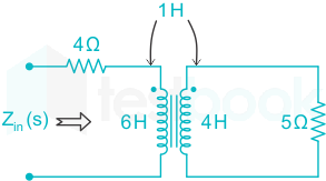
The input impedance, Zin (s), for the network shown is

  1. ((a))

    23s2+46s+204s+5\dfrac{23s^2 + 46s + 20}{4s+5}

  2. ((b))

    7s + 4

  3. ((c))

    6s + 4

  4. ((d))

    25s2+46s+204s+5\dfrac{25s^2 +46s + 20}{4s + 5}

Show Answer
Answer: ((a))

23s2+46s+204s+5\dfrac{23s^2 + 46s + 20}{4s+5}

Concept:

Mutual Inductance:

When two coils are placed close to each other, a change in current in the first coil produces a change in magnetic flux, which cuts not only the coil itself but also the second coil as well. The change in the flux induces a voltage in the second coil, this voltage is called induced voltage and the two coils are said to have a mutual inductance.

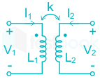
Consider a pair of coupled inductors with self-inductance L1 and L2, magnetically coupled through coupling coefficient k.

Input and output voltage expressions are given as

V1 = jωL1I1 + jωMI2   ...(1)

V2 = jωL2I2 + jωMI1    ...(2)

Where,

ω = 2πf

M=KL1L2M = K\sqrt {{L_1}{L_2}}

M = Mutual inductance

L1 = Inductance of coil one

L2 = Inductance of coil two

Calculation:

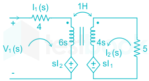
The given circuit in the Laplace domain is 

Apply KVL in the input loop,

V1(s) = (4 + 6s)I1(s) + sI2(s)  ...(1)

Apply KVL in the output loop

I2(s)[5 +4s] + sI1(s) = 0

I2(s)=sI1(s)4s+5I_2(s)=\dfrac{{-sI_1(s)}}{{4s + 5}}

Substitute I2(s) in equation(1)

V1(s)=(4+6s)I1(s)s2I1(s)4s+5V_1(s)=(4+6s)I_1(s)-\dfrac{{s^2I_1(s)}}{{4s + 5}}

V1(s)I1(s)=(6s+4)(4s+5)s24s+5\dfrac{{V_1(s)}}{{I_1(s)}}=\dfrac{{(6s+4)(4s+5)-s^2}}{{4s+5}}

Zin(s)=24s2+16s+30s+20s24s+5Z_{in}(s)=\dfrac{{24s^2+16s+30s+20-s^2}}{{4s+5}}

Zin(s)=23s2+46s+204s+5Z_{in}(s)=\dfrac{{23s^2+46s+20}}{{4s+5}}

62

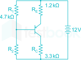
In the BJT circuit shown, beta of the PNP transistor is 100. Assume VBE = -0.7 V. The voltage across RC will be 5 V when R2 is _____ kΩ.

(Round off to 2 decimal places).

63

Let p(z) = z3 + (1 + j) z2 + (2 + j) z + 3, where z is a complex number.

Which one of the following is true?

  1. ((a))

    All the roots cannot be real

  2. ((b))

    conjugate {p(z)} = p(conjugate {z}) for all z

  3. ((c))

    The sum of the roots of p(z) = 0 is a real number

  4. ((d))

    The complex roots of the equation p(z) = 0 come in conjugate pairs

Show Answer
Answer: ((a))

All the roots cannot be real

Concept:

The general form of a cubic equation is ax3 + bx2 + cx + d = 0.

Where a, b, c, and d are constants and a ≠ 0.

Let the roots be p, q, and r

  • The sum of the roots (p + q + r) = - b/a
  • The product of the roots (pqr) = - d/a
  • The sum of the product of any two roots (pq + qr + rp) = c/a


Calculation:

Given p(z) = z3 + (1 + j) z2 + (2 + j) z + 3

Sum of the roots (p + q + r) = - (1 + j)

Product of the roots (pqr) = - 3

Sum of the roots is complex, so all the roots cannot be real.

64

Which one of the following vector functions represents a magnetic field B\vec{B} ?

(x̂, ŷ, and ẑ are unit vectors along x-axis, y-axis and z-axis, respectively)

  1. ((a))

    10x x̂  - 30z ŷ + 20y ẑ  

  2. ((b))

    10y x̂ + 20x ŷ - 10z ẑ 

  3. ((c))

    10x x̂ + 20y ŷ - 30z ẑ 

  4. ((d))

    10z x̂ + 20y ŷ - 30x ẑ 

Show Answer
Answer: ((c))

10x x̂ + 20y ŷ - 30z ẑ 

Concept:

The magnetic field forms a closed loop, i.e. the amount of field leaving a point equals the amount entering. i.e. Magnetic monopoles do not exist.

Since the divergence of a field gives the net outflow of a field and is calculated as .F∇ .\vec F

So, ∇ ⋅ B = 0

B = Magnetic flux density

Since B is related to H (magnetic field intensity) as:

B = μH

so, ∇ ⋅ H = 0

Application:

Option: 1

B = 10x x̂  - 30z ŷ + 20y ẑ  

B=Bxx+Byy+Bzz=10xx+(30z)y+20yz=10∇ ⋅ B = \frac{{\partial {B_x}}}{{\partial x}} + \frac{{\partial {B_y}}}{{\partial y}} + \frac{{\partial {B_z}}}{{\partial z}} = \frac{{\partial 10x}}{{\partial x}} + \frac{{\partial ( - 30z)}}{{\partial y}} + \frac{{\partial 20y}}{{\partial z}} = 10

∇ ⋅ B ≠ 0, so function does not represent magnetic field.

Option: 2

B = 10y x̂ + 20x ŷ - 10z ẑ 

B=Bxx+Byy+Bzz=10yx+20xy+(10z)z=10\nabla ⋅ B = \frac{{\partial {B_x}}}{{\partial x}} + \frac{{\partial {B_y}}}{{\partial y}} + \frac{{\partial {B_z}}}{{\partial z}} = \frac{{\partial 10y}}{{\partial x}} + \frac{{\partial 20x}}{{\partial y}} + \frac{{\partial ( - 10z)}}{{\partial z}} = - 10

∇ ⋅ B ≠ 0, so function does not represent magnetic field.

Option: 3

B = 10x x̂ + 20y ŷ - 30z ẑ 

B=Bxx+Byy+Bzz=10xx+20yy+(30z)z=10+2030=0\nabla ⋅ B = \frac{{\partial {B_x}}}{{\partial x}} + \frac{{\partial {B_y}}}{{\partial y}} + \frac{{\partial {B_z}}}{{\partial z}} = \frac{{\partial 10x}}{{\partial x}} + \frac{{\partial 20y}}{{\partial y}} + \frac{{\partial ( - 30z)}}{{\partial z}} = 10 + 20 - 30 = 0

∇ ⋅ B = 0, so function represent magnetic field.

Option: 4

B = 10z x̂ + 20y ŷ - 30x ẑ 

B=Bxx+Byy+Bzz=10zx+20yy+(30x)z=20\nabla ⋅ B = \frac{{\partial {B_x}}}{{\partial x}} + \frac{{\partial {B_y}}}{{\partial y}} + \frac{{\partial {B_z}}}{{\partial z}} = \frac{{\partial 10z}}{{\partial x}} + \frac{{\partial 20y}}{{\partial y}} + \frac{{\partial ( - 30x)}}{{\partial z}} = 20

∇ ⋅ B ≠ 0, so function does not represent magnetic field.

65

Suppose IA, IB and IC are a set of unbalanced current phasors in a three-phase system. The phase-B zero-sequence current IB0 = 0.1 ∠0° p.u. If phase-A current IA = 1.1 ∠0° p.u. and phase-C current IC = (1 ∠120° + 0.1) p.u. then IB in p.u. is

  1. ((a))

    1 ∠240° - 0.1 ∠0°

  2. ((b))

    1.1 ∠240° - 0.1 ∠0°

  3. ((c))

    1.1 ∠-120° + 0.1 ∠0°

  4. ((d))

    1 ∠-120° + 0.1 ∠0° 

Show Answer
Answer: ((d))

1 ∠-120° + 0.1 ∠0° 

Concept:

Fortescue’s Theorem:

A unbalance set of ‘n’ phasors may be resolved into (n - 1) balance n-phase system of different phase sequence and one zero phase sequence system.

A zero-phase sequence system is one in which all phasors are of equal magnitude and angle.

Considered three phasors are represented by a, b, c in such a way that their phase sequence is (a b c).

The positive phase sequence will be (a b c) and the negative phase sequence will be (a c b).

Assumed that subscript 0, 1, 2 refer to zero sequences, positive sequence, negative sequence respectively.

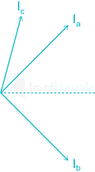
Current Ia, Ib, Ic represented an unbalance set of current phasor as shown,

Each of the original unbalance phasor is the sum of its component and it can be written as,

Ia = Ia0 + Ia1 + Ia2

Ib = Ib0 + Ib1 + Ib2

Ic = Ic0 + Ic1 + Ic2

For a balance position phase sequence (a b c) we can write the following relation,

Ia0 = Ib0 = Ic0

Ib1 = α2 Ia1

Ic1 = α Ia1

Ib2 = α Ia2

Ic22 Ia2

From the above equation Ia, Ib, Ic can be written in terms of phase sequence component,

Ia = Ia0 + Ia1 + Ia2

Ib = Ib0 +  α2 Ia1 + α Ia2

Ic = Ia0 + α Ia1 + α2 Ia2

The above equation can be written in form of Matrix as shown,

\(\left[ {\begin{array}{{20}{c}} {{I_a}}\ {{I_b}}\ {{I_c}} \end{array}} \right] = \left[ {\begin{array}{{20}{c}} 1&1&1\ 1&{{\alpha ^2}}&\alpha \ 1&\alpha &{{\alpha ^2}} \end{array}} \right]\left[ {\begin{array}{*{20}{c}} {{I_{a0}}}\ {{I_{a1}}}\ {{I_{a2}}} \end{array}} \right]\)
Calculation:

Given,

IB0 = 0.1 ∠0° p.u

IA0 = IB0 = IC0 = 0.1 ∠0° p.u

IA = 1.1 ∠0° p.u.

IC = (1 ∠120° + 0.1) p.u.
From the above concept,

IA = IA0 + IA1 + IA2

IA - IA0 = IA1 + IA2 = 1.1 ∠0° + 0.1 ∠0° p.u = 1 ∠0° p.u

IA1 + IA2 = 1 ∠0° p.u .... (1)

IC = IC0 + IC1 + IC2 = IA0 + α IA12 IA2

1 ∠120° + 0.1 = 0.1 ∠0° + α IA12 IA2

α IA12 IA2 = 1 ∠120° .... (2)

Adding equation (1) and (2),

(IA1 + IA2) + (α IA12 IA2) = 1 ∠0° + 1 ∠120°

IA1(α + 1) + IA22 + 1)  = 1 ∠0° + 1 ∠120° (Since, 1 + α + α2 = 0 ⇒ 1 + α = -α2)

IA1(-α2) + IA2(-α)  = 1 ∠0° + 1 ∠120°

α2 IA1 + α IA2 = 1 ∠-120° .... (3)

From above concept,

IB = IA0 + α2 IA1 + α IA2

IB = 0.1 ∠0° + 1 ∠-120°

Attempt this paper under real exam conditions

Timed interface, section switching, instant scoring, and question-by-question analytics — free.

Start Timed Attempt