Official Paper

GATE EE 2020 Official Paper (Previous Year Paper)

65 questions · 180 minutes · with answers · free

General Aptitude (10 questions)

1

This book, including all its chapters, _______ interesting. The students as well as the instructor _________ in agreement about it.

  1. ((a))

    is, was

  2. ((b))

    are, are

  3. ((c))

    is, are

  4. ((d))

    were, was

Show Answer
Answer: ((c))

is, are

The correct answer is option 3- is, are

The given question is on the subject-verb agreement rule in English grammar. 

In the first sentence, the subject is the singular noun 'book'. It will take a verb in the singular form. Thus, 'is' is the correct fit for the blank.

In the second sentence, the conjunction phrase 'as well as' has been used. It is followed by a verb agreeing with the first subject of the sentence- i.e. the subject present before the phrase.

Thus the correct fit for the blank is 'are', as it agrees with the plural subject 'students'. 

Note: There is no indication of the events to have occurred in the past. Thus we cannot consider any verb in the past tense for any of the blanks.

2

People were prohibited _______ their vehicles near the entrance of the main administrative building.

  1. ((a))

    to park

  2. ((b))

    from parking

  3. ((c))

    parking

  4. ((d))

    to have parked

Show Answer
Answer: ((b))

from parking

The correct answer is option 2- from parking

The verb prohibit means to forbid or prevent; it is followed by the preposition from.

The presence of the preposition from necessitates the use of the verb following it to be in its present participle form. 

Thus the correct sentence is: People were prohibited from parking their vehicles near the entrance of the main administrative building. 

Note: We cannot use 'to' after prohibit.

3

Select the word that fits the analogy:

Do : Undo ∷ Trust :

  1. ((a))

    Entrust

  2. ((b))

    Intrust

  3. ((c))

    Distrust

  4. ((d))

    Untrust

Show Answer
Answer: ((c))

Distrust

The correct answer is option 3- Distrust

In the given word problem, we have to find the link between the first and the second words in each set. 

When we look at 'Do' and 'Undo', it becomes easy for us to understand that we need to find the antonym of the word trust.

Trust: believe in the reliability, truth, or ability of

Distrustdoubt the honesty or reliability of; regard with suspicion

Thus we can see that the antonym of trust is distrust.

The meaning of the other words-

Entrustassign the responsibility for doing something to (someone)

Intrust: it means the same as 'entrust' (archaic and obsolete usage)

Untrust: it means the same as 'distrust' (archaic and obsolete usage)

4

Stock markets _________ at the news of the coup.

  1. ((a))

    poised

  2. ((b))

    plunged

  3. ((c))

    plugged

  4. ((d))

    probed

Show Answer
Answer: ((b))

plunged

The correct answer is option 2- plunged

From the context, it is clear that we have to find out the reaction of the stock market to the news of the coup. A stock market can rise, fall or remain stable. 

Plungedfell suddenly and uncontrollably; suffered a rapid decrease in value

Thus 'plunged' fits the blank both grammatically and contextually. 

The meaning of the other words-

Poisedbeen or caused to be balanced or suspended

Pluggedblocked or filled in (a hole or cavity)

Probedphysically explored or examined (something) with the hands or an instrument

5

If P, Q, R, S are four individuals, how many teams of size exceeding one can be formed, with Q as a member?

  1. ((a))

    5

  2. ((b))

    6

  3. ((c))

    7

  4. ((d))

    8

Show Answer
Answer: ((c))

7

Case 1: The number of teams with 2 members can be formed with Q as a member

Out of the 2 members, one member is Q and another member can be selected from the remaining three members.

The number of teams can be formed =3C1=3 = {3_{{C_1}}} = 3

Case 2: The number of teams with 3 members can be formed with Q as a member

Out of the 3 members, one member is Q and another 2 members can be selected from the remaining three members.

The number of teams can be formed =3C2=3 = {3_{{C_2}}} = 3

Case 3: The number of teams with 4 members can be formed with Q as a member

Out of the 4 members, one member is Q and another 3 members can be selected from the remaining three members.

The number of teams can be formed =3C3=1 = {3_{{C_3}}} = 1

Now, the total number of teams can be formed = 3 + 3 + 1 = 7

6

Non-performing Assets (NPAs) of a bank in India is defined as an asset, which remains unpaid by a borrower for a certain period of time in terms of interest, principal, or both. Reserve Bank of India (RBI) has changed the definition of NPA thrice during 1993-2004, in terms of the holding period of loans. The holding period was reduced by one quarter each time. In 1993, the holding period was four quarters (360 days).

Based on the above paragraph, the holding period of loans in 2004 after the third revision was ________ days.

  1. ((a))

    45

  2. ((b))

    90

  3. ((c))

    135

  4. ((d))

    180

Show Answer
Answer: ((b))

90

Initial holding period = 360 days

Number of days for each quarter = 90 days

It is given that the holding period was reduced by one quarter each time i.e. reduced by 90 days each time and RBI has changed the definition of NPA thrice during 1993-2004.

After the first revision, the holding period of loans = 360 – 90 = 270

After the second revision, the holding period of loans = 270 – 90 = 180

After the third revision, the holding period of loans = 180 – 90 = 90

7

Select the next element of the series: Z, WV, RQP, ________.

  1. ((a))

    LKJI

  2. ((b))

    JIHG

  3. ((c))

    KJIH

  4. ((d))

    NMLK

Show Answer
Answer: ((c))

KJIH

The given series: Z, WV, RQP

In the above series, each time the number of letters in the elements is increased by 1.

So, the next element will have four letters.

If we assign a number to each in alphabetical order i.e. A = 1, B = 2, C = 3, ….; the corresponding numbers for the above series will be

Z (26), WV (23, 22), RQP (18, 17, 16)

The difference between the first letters of the first two elements is 26 – 23 = 3

The difference between the first letters of the second and third elements is 23 – 18 = 5

So, the difference between the first letters of the third and fourth elements will be 7

So, the starting letter of the fourth element will be 11th (18 – 7 = 11) letter in the alphabetical order i.e. the starting letter will be K.

The next element in the series will be KJIH

8

In four-digit integer numbers from 1001 to 9999, the digit group "37" (in the same sequence) appears _______ times.

  1. ((a))

    270

  2. ((b))

    279

  3. ((c))

    280

  4. ((d))

    299

Show Answer
Answer: ((c))

280

In four-digit integer, the digit group "37" (in the same sequence) appears as given below.

Case 1: _ _ 3 7

In this case, 37 appears once in each hundred i.e.

Once in 1101 to 1199 (1137) and

Once in 1201 to 1299 (1237) …

There are 90 such instances from 1001 to 9999.

Case 2: _ 3 7 _

In this case, 37 appears 10 times in each thousand i.e.

10 times in 1101 to 1999 (1370 to 1379) and

Once in 2101 to 2999 (2370 to 2379) …

There are 9 such instances from 1001 to 9999.

Total number of times that 37 have appeared = 10 × 9 = 90

Case 3:  3 7 _ _

In this case, 37 appears 100 times i.e. from 3700 to 3799

Therefore, total number of times the digit group "37" appears = 100 + 90 + 90 = 280

Common mistake:

The question is to find how many times the digit group "37" appears but not in how many numbers it appears.

Ex: 3737, in this number 37 appears two times. We need to count the 37 in this case twice but not once.

If the question is to find in how many numbers, the digit group "37" appears, then the answer will be 279.

9

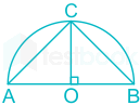
Given a semicircle with O as the centre, as shown in the figure, the ratio AC+CBAB\frac{{\overline {AC} + \overline {CB} }}{{\overline {AB} }} is _____, where  AC,;CB;;and;;AB\overline {AC} ,;\overline {CB} ;;and;;\overline {AB}  are chords.

  1. ((a))

    2\sqrt 2

  2. ((b))

    3\sqrt 3

  3. ((c))

    2

  4. ((d))

    3

Show Answer
Answer: ((a))

2\sqrt 2

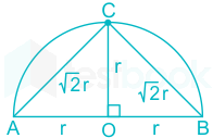
Let the radius of the semicircle is r as shown in the diagram given below.

Now, OA = OC = OB = r

AB = OA + OB = 2r

AC=(OA)2+(OC)2=r2+r2=2r\overline {AC} = \sqrt {{{\left( {OA} \right)}^2} + {{\left( {OC} \right)}^2}} = \sqrt {{r^2} + {r^2}} = \sqrt 2 r

BC=(OB)2+(OC)2=r2+r2=2r\overline {BC} = \sqrt {{{\left( {OB} \right)}^2} + {{\left( {OC} \right)}^2}} = \sqrt {{r^2} + {r^2}} = \sqrt 2 r

The ratio AC+CBAB=2r+2r2r=2\frac{{\overline {AC} + \overline {CB} }}{{\overline {AB} }} = \frac{{\sqrt 2 r + \sqrt 2 r}}{{2r}} = \sqrt 2

10

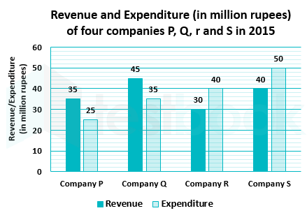
The revenue and expenditure of four different companies P, Q, R and S in 2015 are shown in the figure. If the revenue of company Q in 2015 was 20% more than that in 2014, and company Q had earned a profit of 10% on expenditure in 2014, then its expenditure (in million rupees) in 2014 was

  1. ((a))

    32.7

  2. ((b))

    33.7

  3. ((c))

    34.1

  4. ((d))

    35.1

Show Answer
Answer: ((c))

34.1

From the figure, the revenue of company Q in 2015 = 45 million rupees

Given that the revenue of company Q in 2015 was 20% more than that in 2014

The revenue of company Q in 2015 = 1.2 times the revenue of company Q in 2014

⇒ The revenue of company Q in 2014 = 45/1.2 = 37.5 million rupees

Given that the company Q had earned a profit of 10% on expenditure in 2014

% of profit = ((revenue – expenditure)/expenditure) × 100

Let the expenditure in 2014 is ‘x’ million rupees

10=37.5xx×100\Rightarrow 10 = \frac{{37.5 - x}}{x} \times 100

⇒ 1.1 x = 37.5

⇒ x = 34.09 ≈ 34.1 million rupees

Common mistake:

It is mentioned that the company Q had earned a profit of 10% on expenditure in 2014.

If we calculate the profit on revenue, the answer will be 33.7 which is mentioned in one of the options given.

Electrical Engineering (55 questions)

11

ax3 + bx2 + cx + d is a polynomial on real x over real coefficients a, b, c, d wherein a ≠ 0. Which of the following statements is true?

  1. ((a))

    d can be chosen to ensure that x = 0 is a root for any given set a, b, c.

  2. ((b))

    No choice of coefficients can make all roots identical.

  3. ((c))

    a, b, c, d can be chosen to ensure that all roots are complex.

  4. ((d))

    c alone can ensure that all roots are real.

Show Answer
Answer: ((a))

d can be chosen to ensure that x = 0 is a root for any given set a, b, c.

The given polynomial is: ax3 + bx2 + cx + d = 0

Option 1:

At d = 0, the above equation becomes

ax3 + bx2 + cx = 0

⇒ x (ax2 + bx + c) = 0

Now, it is clear that x = 0 is a root for any given set a, b, c.

Therefore, the given statement is correct.

Option 2:

The given polynomial can be expressed as follows.

x3+bax2+cax+da=0{x^3} + \frac{b}{a}{x^2} + \frac{c}{a}x + \frac{d}{a} = 0

Let the above equation has three equal roots and x = r be a root.

Now, x3+bax2+cax+da=(xr)2=0{x^3} + \frac{b}{a}{x^2} + \frac{c}{a}x + \frac{d}{a} = {\left( {x - r} \right)^2} = 0

x3+bax2+cax+da=x33rx2+3r2xr3=0 \Rightarrow {x^3} + \frac{b}{a}{x^2} + \frac{c}{a}x + \frac{d}{a} = {x^3} - 3r{x^2} + 3{r^2}x - {r^3} = 0

By comparing on both sides,

ba=3r,ca=3r2,da=r3 \Rightarrow \frac{b}{a} = - 3r,\frac{c}{a} = 3{r^2},\frac{d}{a} = - {r^3}

By using the above relations, the conditions to get all the roots equal are

b2 = 3ac and bc = 9ad

If we choose the values of a, b, c and d which satisfies the above relations, the roots will be equal, and the corresponding root will be r=b3ar = - \frac{b}{{3a}}

Therefore, the given statement is incorrect.
Option 3:

The given polynomial is: ax3 + bx2 + cx + d = 0

All the coefficients a, b, c, and d are real

As the coefficients are real, the complex roots must occur in conjugate.

The number of possible complex roots are either 0 or 2.

So, no choice of coefficients can make all roots complex.

Therefore, the given statement is incorrect.
Option 4:

c alone cannot ensure that all roots are real. It depends on all the coefficients.

Therefore, the given statement is incorrect.
12

Which of the following is NOT true for all possible non-zero choices of integers m, n; m ≠ n, or all possible non-zero choices of real numbers p, q; p ≠ q, as applicable?

  1. ((a))

    \(\frac{1}{\pi }\mathop \smallint \limits_0^\pi \sin m\theta \sin n\theta d\theta = 0\)

  2. ((b))

    \(\frac{1}{{2\pi }}\mathop \smallint \limits_{ - \pi /2}^{\pi /2} \sin p\theta \sin q\theta d\theta = 0\)

  3. ((c))

    \(\frac{1}{{2\pi }}\mathop \smallint \limits_{ - \pi }^\pi \sin p\theta \cos q\theta d\theta = 0\)

  4. ((d))

    \(\mathop {\lim }\limits_{\alpha \to \infty } \frac{1}{{2\alpha }}\mathop \smallint \limits_{ - \alpha }^\alpha \sin p\theta \sin q\theta d\theta = 0\)

Show Answer
Answer: ((b))

\(\frac{1}{{2\pi }}\mathop \smallint \limits_{ - \pi /2}^{\pi /2} \sin p\theta \sin q\theta d\theta = 0\)

Option 1:

\(\frac{1}{\pi }\mathop \smallint \limits_0^\pi \sin m\theta \sin n\theta d\theta \)

\( = \frac{1}{{2\pi }}\mathop \smallint \limits_0^\pi \cos \left( {m - n} \right)\theta - \cos \left( {m + n} \right)\theta d\theta \)

=12π[sin(mn)θmnsin(m+n)θm+n]0π=0 = \frac{1}{{2\pi }}\left[ {\frac{{\sin \left( {m - n} \right)\theta }}{{m - n}} - \frac{{\sin \left( {m + n} \right)\theta }}{{m + n}}} \right]_0^\pi = 0

Therefore, Option (1) is correct.

Option 2:

\(\frac{1}{{2\pi }}\mathop \smallint \limits_{ - \pi /2}^{\pi /2} \sin p\theta \sin q\theta d\theta \)

\( = \frac{1}{{4\pi }}\mathop \smallint \limits_{ - \frac{\pi }{2}}^{\frac{\pi }{2}} \cos \left( {p - q} \right)\theta - \cos \left( {p + q} \right)\theta d\theta \)

=14π[sin(pq)θpqsin(p+q)θp+q]π2π2 = \frac{1}{{4\pi }}\left[ {\frac{{\sin \left( {p - q} \right)\theta }}{{p - q}} - \frac{{\sin \left( {p + q} \right)\theta }}{{p + q}}} \right]_{ - \frac{\pi }{2}}^{\frac{\pi }{2}}

=12π[sin(pq)π2;pqsin(p+q)π2p+q] = \frac{1}{{2\pi }}\left[ {\frac{{\sin \left( {p - q} \right)\frac{\pi }{2};}}{{p - q}} - \frac{{\sin \left( {p + q} \right)\frac{\pi }{2}}}{{p + q}}} \right]

The above expression not necessarily is zero. Therefore, Option (2) is incorrect.

Option 3:

\(\frac{1}{{2\pi }}\mathop \smallint \limits_{ - \pi }^\pi \sin p\theta \cos q\theta d\theta \)

\( = \frac{1}{{4\pi }}\mathop \smallint \limits_{ - \pi }^\pi \sin \left( {p + q} \right)\theta + \sin \left( {p - q} \right)\theta d\theta \)

=14π[cos(p+q)θp+q+cos(pq)θpq]ππ = \frac{1}{{4\pi }}\left[ { - \frac{{\cos \left( {p + q} \right)\theta }}{{p + q}} + \frac{{\cos \left( {p - q} \right)\theta }}{{p - q}}} \right]_{ - \pi }^\pi

=14π[cos(p+q)π;p+q+cos(p+q)πp+q+cos(p+q)π;p+qcos(p+q)πp+q]=0 = \frac{1}{{4\pi }}\left[ { - \frac{{\cos \left( {p + q} \right)\pi ;}}{{p + q}} + \frac{{\cos \left( {p + q} \right)\pi }}{{p + q}} + \frac{{\cos \left( {p + q} \right)\pi ;}}{{p + q}} - \frac{{\cos \left( {p + q} \right)\pi }}{{p + q}}} \right] = 0

Therefore, Option (3) is correct.

Option 4:

\(\frac{1}{{2\alpha }}\mathop \smallint \limits_{ - \alpha }^\alpha \sin p\theta \sin q\theta d\theta \)

\( = \frac{1}{{4\alpha }}\mathop \smallint \limits_{ - \alpha }^\alpha \cos \left( {p - q} \right)\theta - \cos \left( {p + q} \right)\theta d\theta \)

=14α[sin(pq)θpqsin(p+q)θp+q]αα = \frac{1}{{4\alpha }}\left[ {\frac{{\sin \left( {p - q} \right)\theta }}{{p - q}} - \frac{{\sin \left( {p + q} \right)\theta }}{{p + q}}} \right]_{ - \alpha }^\alpha

=12α[sin(pq)αpqsin(p+q)αp+q] = \frac{1}{{2\alpha }}\left[ {\frac{{\sin \left( {p - q} \right)\alpha }}{{p - q}} - \frac{{\sin \left( {p + q} \right)\alpha }}{{p + q}}} \right]

\(\mathop {\lim }\limits_{\alpha \to \infty } \frac{1}{{2\alpha }}\mathop \smallint \limits_{ - \alpha }^\alpha \sin p\theta \sin q\theta d\theta \)

=limα12α[sin(pq)αpqsin(p+q)αp+q] = \mathop {\lim }\limits_{\alpha \to \infty } \frac{1}{{2\alpha }}\left[ {\frac{{\sin \left( {p - q} \right)\alpha }}{{p - q}} - \frac{{\sin \left( {p + q} \right)\alpha }}{{p + q}}} \right]

=limα12[sin(pq)α(pq)αsin(p+q)α(p+q)α]=0 = \mathop {\lim }\limits_{\alpha \to \infty } \frac{1}{2}\left[ {\frac{{\sin \left( {p - q} \right)\alpha }}{{\left( {p - q} \right)\alpha }} - \frac{{\sin \left( {p + q} \right)\alpha }}{{\left( {p + q} \right)\alpha }}} \right] = 0

Therefore, Option (4) is correct.

13

Which of the following statements is true about the two-sided Laplace transform?

  1. ((a))

    It exists for every signal that may or may not have a Fourier transform

  2. ((b))

    It has no poles for any bounded signal that is non-zero only inside a finite time interval

  3. ((c))

    The number of finite poles and finite zeroes must be equal

  4. ((d))

    If a signal can be expressed as a weighted sum of shifted one sided exponential, then its Laplace Transform will have no poles

Show Answer
Answer: ((b))

It has no poles for any bounded signal that is non-zero only inside a finite time interval

The Fourier transform of x(t) is, denoted by X(jω), is defined as:

\(X\left( {j\omega } \right) = \mathop \smallint \limits_{ - \infty }^\infty x\left( t \right){e^{ - j\omega t}}dt\)

The Laplace transform of x(t), denoted by X(s), is defined as:

\(X\left( s \right) = \mathop \smallint \limits_{ - \infty }^\infty x\left( t \right){e^{ - st}}dt\)

Where s is a continuous complex variable.

We can also express s as: s = σ + jω

Where σ and ω are the real and imaginary parts of s, respectively

The Laplace transform can be written as:

\(X\left( {\sigma + j\omega } \right) = \mathop \smallint \limits_{ - \infty }^\infty x\left( t \right){e^{ - \left( {\sigma + j\omega } \right)t}}dt = \mathop \smallint \limits_{ - \infty }^\infty \left( {x\left( t \right){e^{ - \sigma t}}} \right){e^{ - j\omega t}}dt\)

By comparing the above Laplace and Fourier transform equations, it is clear that Laplace transform of x(t) is equal to the Fourier transform of x(t)eσtx\left( t \right){e^{ - \sigma t}}.

When σ = 0 or s = jω, both are identical.

\({\left. {X\left( s \right)} \right|{s = j\omega }} = X\left( {j\omega } \right) = \mathop \smallint \limits{ - \infty }^\infty x\left( t \right){e^{ - j\omega t}}dt\)

That is, Laplace transform generalizes Fourier transform.

Option 1:

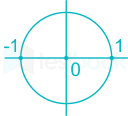
Region of Convergence (ROC):

ROC indicates when the Laplace transform of x(t) converges.

That is, if \(\left| {X\left( s \right)} \right| = \left| {\mathop \smallint \limits_{ - \infty }^\infty x\left( t \right){e^{ - st}}dt} \right| \to \infty\) then the Laplace transform does not converge at point s.

Employing s = σ + jω and |ejωt| = 1, Laplace transform exists if

\(\left| {X\left( {\sigma + j\omega } \right)} \right| \le \mathop \smallint \limits_{ - \infty }^\infty \left| {x\left( t \right){e^{ - \left( {\sigma + j\omega } \right)t}}} \right|dt = \mathop \smallint \limits_{ - \infty }^\infty \left| {x\left( t \right){e^{ - \sigma t}}} \right|dt < \infty\)

The set of values of σ which satisfies the above equation is called the ROC.

If \(\left| {X\left( {j\omega } \right)} \right| = \left| {\mathop \smallint \limits_{ - \infty }^\infty x\left( t \right){e^{ - j\omega t}}dt} \right| \to \infty\) then the Fourier transform does not exist. While it exists if \(\left| {X\left( {j\omega } \right)} \right| \le \mathop \smallint \limits_{ - \infty }^\infty \left| {x\left( t \right){e^{ - j\omega t}}} \right|dt = \mathop \smallint \limits_{ - \infty }^\infty \left| {x\left( t \right)} \right|dt < \infty\)

Hence it is possible that the Fourier transform of x(t) does not exist. Also, the Laplace transform does not exist if there is no value of σ satisfies the required ROC equation as explained above.

Therefore, the given statement is incorrect.
Option 2:

Values of s for which X(s) = 0 are the Zeros of X(s)

Values of s for which X(s) = ∞ are the Poles of X(s)

For bounded inputs i.e. finite-amplitude finite width signals, the ROC is entire s plane and ROC never includes any pole. It implies for such signals there are no poles.

Therefore, the two-sided Laplace transform of any bounded input, will not have any poles

Therefore, the given statement is correct.

Option 3:

The number of finite pole and finite zero need not be equal.

Ex: etu(t)LT1s+1;ROC:;s>1{e^{ - t}}u\left( t \right)\mathop \leftrightarrow \limits^{LT} \frac{1}{{s + 1}};ROC:;s > - 1 and pole at s = -1

This has 1 finite pole and no zeroes.

Therefore, the given statement is incorrect.

Option 4:

If a signal can be expressed as a weighted sum of shifted one-sided exponential, then its Laplace Transform will have poles.

Ex: Let x(t)=et+2e(t1)+3e(t2)+x\left( t \right) = {e^{ - t}} + 2{e^{ - \left( {t - 1} \right)}} + 3{e^{ - \left( {t - 2} \right)}} + \cdots

x(s)=1s+1+2ess+1+3e2ss+1+x\left( s \right) = \frac{1}{{s + 1}} + \frac{{2{e^{ - s}}}}{{s + 1}} + \frac{{3{e^{ - 2s}}}}{{s + 1}} + \cdots

x(s)=1+2es+3e2ss+1x\left( s \right) = \frac{{1 + 2{e^{ - s}} + 3{e^{ - 2s}}}}{{s + 1}}

So, x(s) has one pole.

Therefore, the given statement is incorrect.
14

Consider a signal x[n]=(12)n1[n]x\left[ n \right] = {\left( {\frac{1}{2}} \right)^n}1\left[ n \right], where 1[n] = 0 if n < 0, and 1[n] = 1 if n ≥ 0. The z-transform of x[n - k], k > 0 is zk112;z1\frac{{{z^{ - k}}}}{{1 - \frac{1}{2};{z^{ - 1}}}} with region of convergence being

  1. ((a))

    |z| < 2

  2. ((b))

    |z| > 2

  3. ((c))

    |z| < 1/2

  4. ((d))

    |z| > 1/2

Show Answer
Answer: ((d))

|z| > 1/2

Concept:

Z transform:

The Z transform of x(t) is, denoted by X(z), is defined as:

\(X\left( z \right) = \mathop \sum \limits_{n = - \infty }^\infty x\left( n \right){z^{ - n}}\)

anu(n)ZT11az1{a^n}u\left( n \right)\mathop \to \limits^{ZT} \frac{1}{{1 - a{z^{ - 1}}}}; ROC:|z|>|a|

Shifting property:

If x(n)ZTx(z)x\left( n \right)\mathop \to \limits^{ZT} x\left( z \right) ; ROC: R

Then x(nn0)ZTzn0x(z)x\left( {n - {n_0}} \right)\mathop \to \limits^{ZT} {z^{ - {n_0}}}x\left( z \right); ROC: R

The time-shifting will not affect ROC.

Calculation:

Given that, x(n)=(12)n1[n]x\left( n \right) = {\left( {\frac{1}{2}} \right)^n}1\left[ n \right]

Z Transform (ZT) of x(n) will be,

x(z)=zz12=1112z1x\left( z \right) = \frac{z}{{z - \frac{1}{2}}} = \frac{1}{{1 - \frac{1}{2}{z^{ - 1}}}} ; ROC: z>12\left| z \right| > \frac{1}{2}

And, z(x(nk))=;zk112z1z\left( {x\left( {n - k} \right)} \right) = ;\frac{{{z^{ - k}}}}{{1 - \frac{1}{2}{z^{ - 1}}}} ; ROC: z>12\left| z \right| > \frac{1}{2}

15

The value of the following complex integral, with C representing the unit circle centered at origin in the counterclockwise sense, is: \(\mathop \smallint \nolimits_C \frac{{{z^2} + 1}}{{{z^2} - 2z}}dz\)

  1. ((a))

    8πi

  2. ((b))

    -8πi

  3. ((c))

    -πi

  4. ((d))

    πi

Show Answer
Answer: ((c))

-πi

Concept:

Cauchy’s Theorem:

If f(z) is an analytic function and f’(z) is continuous at each point within and on a closed curve C, then

Cf(z)dz=0\mathop \oint \limits_C f\left( z \right)dz = 0

Cauchy’s Integral Formula:

If f(z) is an analytic function within a closed curve and if a is any point within C, then

f(a)=12πiCf(z)zadzf\left( a \right) = \frac{1}{{2\pi i}}\mathop \oint \limits_C \frac{{f\left( z \right)}}{{z - a}}dz

fn(a)=n!2πiCf(z)(za)n+1dz{f^n}\left( a \right) = \frac{{n!}}{{2\pi i}}\mathop \oint \limits_C \frac{{f\left( z \right)}}{{{{\left( {z - a} \right)}^{n + 1}}}}dz

Residue Theorem:

If f(z) is analytic in a closed curve C except at a finite number of singular points within C, then

\(\mathop \smallint \limits_C f\left( z \right)dz = 2\pi i \times \left[ {{\rm{sum;of;residues;at;the;singualr;points;within;C}}} \right]\)

Formula to find residue:

  1. If f(z) has a simple pole at z = a, then

Res;f(a)=limza[(za)f(z)]Res;f\left( a \right) = \mathop {\lim }\limits_{z \to a} \left[ {\left( {z - a} \right)f\left( z \right)} \right]

  1. If f(z) has a pole of order n at z = a, then

\(Res;f\left( a \right) = \frac{1}{{\left( {n - 1} \right)!}}{\left{ {\frac{{{d^{n - 1}}}}{{d{z^{n - 1}}}}\left[ {{{\left( {z - a} \right)}^n}f\left( z \right)} \right]} \right}_{z = a}}\)

Application:

\(\mathop \smallint \nolimits_C \frac{{{z^2} + 1}}{{{z^2} - 2z}}dz\)

\( = \mathop \smallint \nolimits_C \frac{{{z^2} + 1}}{{z\left( {z - 2} \right)}}dz\)

The simple poles are: z = 0, 2

The given region is a unit circle.

The residue at z = 2 is zero as it lies outside the given region.

The reside at z = 0, is given by

=limz0zz2+1z(z2)dz=12 = \mathop {\lim }\limits_{z \to 0} z\frac{{{z^2} + 1}}{{z\left( {z - 2} \right)}}dz = - \frac{1}{2}

The value of the given integral =2πi×(12)=πi = 2\pi i \times \left( { - \frac{1}{2}} \right) = - \pi i

16

xR and xA are, respectively, the rms and average values of x(t) = x(t - T), and similarly, yR and yA are, respectively, the rms and average values of y(t) = kx(t), k, T are independent of t. Which of the following is true?

  1. ((a))

    yA=kxA;;yR=kxR{y_A} = k{x_A};;{y_R} = k{x_R}

  2. ((b))

    yA=kxA;yRkxR{y_A} = k{x_A};{y_R} \ne k{x_R}

  3. ((c))

    yAkxA;yR=kxR{y_A} \ne k{x_A};{y_R} = k{x_R}

  4. ((d))

    yAkxA;yRkxR{y_A} \ne k{x_A};{y_R} \ne k{x_R}

Show Answer
Answer: ((a))

yA=kxA;;yR=kxR{y_A} = k{x_A};;{y_R} = k{x_R}

Concept:

A function f(t) is said to be a periodic function, if f(t ± T) = f(t)

Where T is a time period

The average value of f(t) is given by,

\({f_{avg}} = \frac{1}{T}\mathop \smallint \nolimits_0^T f\left( t \right)dt\)

The RMS value of f(t) is given by,

\({f_{rms}} = \sqrt {\frac{1}{T}\mathop \smallint \nolimits_0^T {{\left( {f\left( t \right)} \right)}^2}} dt\)

Application:

Given that,

xR and xA are, respectively, the RMS and average values of x(t) = x(t – T)

yR and yA are, respectively, the RMS and average values of y(t) = kx(t)

k, T are independent of t.

The average value of x(t) is,

\({x_A} = \frac{1}{T}\mathop \smallint \nolimits_0^T x\left( t \right)dt\)

The average value of y(t) is,

\({y_A} = {\left( {kx} \right)_A} = \frac{1}{T}\mathop \smallint \nolimits_0^T kx\left( t \right)dt = k{x_A}\)

The RMS value of x(t) is,

\({x_R} = \sqrt {\frac{1}{T}\mathop \smallint \nolimits_0^T {x^2}\left( t \right)dt}\)

The RMS value of y(t) is,

\({y_R} = \sqrt {\frac{1}{T}\mathop \smallint \nolimits_0^T {{\left( {kx\left( t \right)} \right)}^2}dt}\)

\(= k\sqrt {\frac{1}{T}\mathop \smallint \nolimits_0^T {{\left( {x\left( t \right)} \right)}^2}dt} = k{x_R}\)

17

A three-phase cylindrical rotor synchronous generator has a synchronous reactance Xs and a negligible armature resistance. The magnitude of per phase terminal voltage is VA and the magnitude of per phase induced emf is EA. Considering the following two statements, P and Q,

P: For any three-phase balanced leading load connected across the terminals of this synchronous generator, VA is always more than EA

Q: For any three-phase balanced lagging load connected across the terminals of this synchronous generator, VA is always less than EA

Which of the following options is correct?

  1. ((a))

    P is false and Q is true

  2. ((b))

    P is true and Q is false

  3. ((c))

    P is false and Q is false

  4. ((d))

    P is true and Q is true

Show Answer
Answer: ((a))

P is false and Q is true

Given that the cylindrical synchronous generator with

Synchronous reactance = XS and

Armature resistance = Ra = 0

Now, the simplified circuit of the synchronous generator looks like as shown below

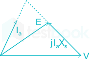
Case 1: The load is lagging in nature.

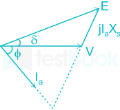
The corresponding phasor diagram is

⇒ |V| < |E|

Case 2: The load is leading in nature.

The corresponding phasor diagram is shown below.

⇒ |V| > |E|

  • A cylindrical rotor synchronous generator (with Ra = 0) has always positive voltage regulation for lagging p.f. loads i.e. EA > VA
  • Whereas it has positive, zero, and negative regulation for leading loads i.e. all cases EA > VA, EA = VA, and EA < VA are possible.


Therefore, statement P is False, and Q is True.

18

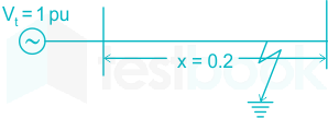
A lossless transmission line with 0.2 pu reactance per phase uniformly distributed along the length of the line, connecting a generator bus to a load bus, is protected up to 80 % of its length by a distance relay placed at the generator bus. The generator terminal voltage is 1 pu. There is no generation at the load bus. The threshold pu current for operation of the distance relay for a solid three phase-to-ground fault on the transmission line is closest to:

  1. ((a))

    1.00

  2. ((b))

    3.61

  3. ((c))

    5.00

  4. ((d))

    6.25

Show Answer
Answer: ((d))

6.25

Line reactance = 0.2 pu

Given that only 80% of the line is protected by distance relay.

So, the reactance of the line as seen by the relay will be

X = 0.8 × 0.2 = 0.16 pu

Terminal voltage, Vt = 1 Pu

The impedance is seen by impedance relay, X=VtIfX = \frac{{{V_t}}}{{{I_f}}}

The threshold pu current for operation of the distance relay If=10.16=6.25;pu{I_f} = \frac{1}{{0.16}} = 6.25;pu

19

Out of the following options, the most relevant information needed to specify the real power (P) at the PV buses in a load flow analysis is

  1. ((a))

    solution of economic load dispatch

  2. ((b))

    rated power output of the generator

  3. ((c))

    rated voltage of the generator

  4. ((d))

    base power of the generator

Show Answer
Answer: ((a))

solution of economic load dispatch

  • The most relevant information needed to specify P at PV buses is the solution of economic load dispatch.
  • Economic load dispatch is a precursor to the load flow study (LFS), i.e. to perform the LFS the first step is to perform the economic load dispatch.
  • The economic load dispatch means the real and reactive power of the generator varies within certain limits and fulfills the load demand with less fuel cost.
  • The economic scheduling of the generators aims to guarantee at all times the optimum combination of the generator connected to the system to supply the load demand.
  • The economic load dispatch problem involves two separate steps. These are the online load dispatch and unit commitment.
  • The unit commitment selects that unit which will anticipate the load of the system over the required period at minimum cost.
  • The online load dispatch distributes the load among the generating unit which is parallel to the system in such a manner as to reduce the total cost of supplying. It also fulfills the minute to the minute requirement of the system.

Note: Generator not always operates at rated power P because as per the demand by the load, P value changes. Base value can be different for different loads.

20

Consider a linear time-invariant system whose input r(t) and output y(t) are related by the following differential equation:

d2y(t)dt2+4y(t)=6r(t)\frac{{{d^2}y\left( t \right)}}{{d{t^2}}} + 4y\left( t \right) = 6r\left( t \right)

The poles of this system are at

  1. ((a))

    +2j, -2j

  2. ((b))

    +2, -2

  3. ((c))

    +4, -4

  4. ((d))

    +4j, -4j

Show Answer
Answer: ((a))

+2j, -2j

Concept:

A transfer function is defined as the ratio of Laplace transform of the output to the Laplace transform of the input by assuming initial conditions are zero.

TF = L[output]/L[input]

TF=C(s)R(s)TF = \frac{{C\left( s \right)}}{{R\left( s \right)}}

For unit impulse input i.e. r(t) = δ(t)

⇒ R(s) = δ(s) = 1

Now transfer function = C(s)

Therefore, the transfer function is also known as the impulse response of the system.

Transfer function = L[IR]

IR = L-1 [TF]

Calculation:

Given the differential equation is,

d2y(t)dt2+4y(t)=6r(t)\frac{{{d^2}y\left( t \right)}}{{d{t^2}}} + 4y\left( t \right) = 6r\left( t \right)

By applying the Laplace transform,

s2 Y(s) + 4 Y(s) = 6 R(s)

Y(s)R(s)=6s2+4 \Rightarrow \frac{{Y\left( s \right)}}{{R\left( s \right)}} = \frac{6}{{{s^2} + 4}}

Poles are the roots of the denominator in the transfer function.

⇒ s2 + 4 = 0

⇒ s = ±2j

21

A single-phase, full-bridge diode rectifier fed from a 230 V, 50 Hz sinusoidal source supplies a series combination of finite resistance, R, and a very large inductance, L. The two most dominant frequency components in the source current are:

  1. ((a))

    50 Hz, 0 Hz

  2. ((b))

    50 Hz, 100 Hz

  3. ((c))

    50 Hz, 150 Hz

  4. ((d))

    150 Hz, 250 Hz

Show Answer
Answer: ((c))

50 Hz, 150 Hz

Concept:

Fourier series of source current in a full bridge rectifier is given by

\({I_s} = \mathop \sum \limits_{n = 1,3,5 \ldots .}^\infty \frac{{4{I_0}}}{{n\pi }}\sin n\omega t\)

For n = 1, 3, 5, ......

The most dominant frequency components in the above expression are f, 3f

Application:

A single-phase, full-bridge diode rectifier fed from a 230 V, 50 Hz sinusoidal source

Dominant frequencies = f, 3f

= 50 and 150 Hz

22

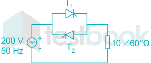
Thyristor T1 is triggered at an angle α (in degree), and T2 at angle 180° + α, in each cycle of the sinusoidal input voltage. Assume both thyristors to be ideal. To control the load power over the range 0 to 2 kW, the minimum range of variation in α is: (Assume that the load is inductive load)

  1. ((a))

    0° to 60°

  2. ((b))

    0° to 120°

  3. ((c))

    60° to 120°

  4. ((d))

    60° to 180°

Show Answer
Answer: ((d))

60° to 180°

Concept:

In a single-phase AC voltage controller, the range of variation in α is

Resistive load: 0 < α < π

Inductive load: ϕ < α < π

Where ϕ is the load angle and α is the firing angle

Calculation:

The given circuit is a single-phase full-wave AC voltage controller.

Load = 10∠60°

Load angle (ϕ) = 60°

The load is inductive and hence current is lagging the voltage by 60°.

It is possible to have control for a range of 60° to 180°.

23

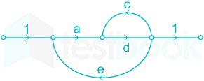
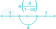
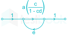
Which of the options is an equivalent representation of the signal flow graph shown here?

  1. ((a))

  2. ((b))

  3. ((c))

  4. ((d))

Show Answer
Answer: ((c))

Concept:

According to Mason’s gain formula, the transfer function is given by

\(TF = \frac{{\mathop \sum \nolimits_{k = 1}^n {M_k}{{\rm{\Delta }}_k}}}{{\rm{\Delta }}}\)

Where, n = no of forward paths

Mk = kth forward path gain

Δk = the value of Δ which is not touching the kth forward path

Δ = 1 – (sum of the loop gains) + (sum of the gain product of two non-touching loops) – (sum of the gain product of three non-touching loops)

Application:

In the given signal flow graph,

Forward paths: P1 = ad

Loops: L1 = cd, L2 = ade

Δ = 1 – (cd + ade)

Δ1 = 1

Transfer function =ad1(cd+ade) = \frac{{ad}}{{1 - \left( {cd + ade} \right)}}

Now, let us check the options.

Option 1:

Forward paths: P1 = a(d + c)

Loops: L1 = ae(d + c)

Δ = 1 – ae(d + c)

Δ1 = 1

Transfer function =a(d+c)1ae(d+c) = \frac{{a\left( {d + c} \right)}}{{1 - ae\left( {d + c} \right)}}

Option 2:

Forward paths: P1 = d(a + c)

Loops: L1 = de(a + c)

Δ = 1 – de(a + c)

Δ1 = 1

Transfer function =d(a+c)1de(a+c) = \frac{{d\left( {a + c} \right)}}{{1 - de\left( {a + c} \right)}}

Option 3:

Forward paths: P1=a(d1cd){P_1} = a\left( {\frac{d}{{1 - cd}}} \right)

Loops: L1=ae(d1cd){L_1} = ae\left( {\frac{d}{{1 - cd}}} \right)

Δ=1ae(d1cd){\rm{\Delta }} = 1 - ae\left( {\frac{d}{{1 - cd}}} \right)

Δ1 = 1

Transfer function =a(d1cd)1ae(d1cd)=ad1(cd+ade) = \frac{{a\left( {\frac{d}{{1 - cd}}} \right)}}{{1 - ae\left( {\frac{d}{{1 - cd}}} \right)}} = \frac{{ad}}{{1 - \left( {cd + ade} \right)}}

Option 4:

Forward paths: P1=a(c1cd){P_1} = a\left( {\frac{c}{{1 - cd}}} \right)

Loops: L1=ae(c1cd){L_1} = ae\left( {\frac{c}{{1 - cd}}} \right)

Δ=1ae(c1cd){\rm{\Delta }} = 1 - ae\left( {\frac{c}{{1 - cd}}} \right)

Δ1 = 1

Transfer function =a(c1cd)1ae(c1cd)=ad1(cd+ace) = \frac{{a\left( {\frac{c}{{1 - cd}}} \right)}}{{1 - ae\left( {\frac{c}{{1 - cd}}} \right)}} = \frac{{ad}}{{1 - \left( {cd + ace} \right)}}

Hence the signal graph in option (3) is the equivalent representation of the signal flow graph given in the question.

24

A common-source amplifier with a drain resistance, RD = 4.7 kΩ is powered using a 10 V power supply. Assuming that the transconductance, gm, is 520 μA/V, the voltage gain of the amplifier is closest to:

  1. ((a))

    -2.44

  2. ((b))

    -1.22

  3. ((c))

    1.22

  4. ((d))

    2.44

Show Answer
Answer: ((a))

-2.44

Concept:

From the AC model of a common source amplifier, the voltage gain is given by

V0Vi=Av=gmRD\frac{{{V_0}}}{{{V_i}}} = {A_v} = - {g_m}{R_D}

gis the transconductance

RD is the drain resistance

Calculation:

Given that, drain resistance, RD = 4.7 kΩ

Transconductance, gm = 520 × 10-6 A/V

Power supply = 10 V

The voltage gain is given by

V0Vi=gmRD=0.52×4.7=2.44\frac{{{V_0}}}{{{V_i}}} = - {g_m}{R_D} = - 0.52 \times 4.7 = - 2.44

25

A sequence detector is designed to detect precisely 3 digital inputs, with overlapping sequences detectable. For the sequence (1,0,1) and input data (1,1,0,1,0,0,1,1,0,1,0,1,1,0), what is the output of this detector?

  1. ((a))

    1,1,0,0,0,0,1,1,0,1,0,0

  2. ((b))

    0,1,0,0,0,0,0,1,0,1,0,0

  3. ((c))

    0,1,0,0,0,0,0,1,0,1,1,0

  4. ((d))

    0,1,0,0,0,0,0,0,1,0,0,0

Show Answer
Answer: ((b))

0,1,0,0,0,0,0,1,0,1,0,0

A sequence detector is a sequential circuit that outputs 1 when a particular pattern of bits sequentially arrives at its data input.

Given input data = 1,1,0,1,0,0,1,1,0,1,0,1,1,0

Overlapping sequences detectable.

The below table shows the output for each sequence.

InputOutput
1,1,0,1,0,0,1,1,0,1,0,1,1,00
1,1,0,1,0,0,1,1,0,1,0,1,1,01
1,1,0,1,0,0,1,1,0,1,0,1,1,00
1,1,0,1,0,0,1,1,0,1,0,1,1,00
1,1,0,1,0,0,1,1,0,1,0,1,1,00
1,1,0,1,0,0,1,1,0,1,0,1,1,00
1,1,0,1,0,0,1,1,0,1,0,1,1,00
1,1,0,1,0,0,1,1,0,1,0,1,1,01
1,1,0,1,0,0,1,1,0,1,0,1,1,00
1,1,0,1,0,0,1,1,0,1,0,1,1,01
1,1,0,1,0,0,1,1,0,1,0,1,1,00
1,1,0,1,0,0,1,1,0,1,0,1,1,00


The output = 0,1,0,0,0,0,0,1,0,1,0,0

26

Consider the initial value problem below. The value of y at x = In 2, (rounded off to 3 decimal places) is

dydx=2xy,;y(0)=1\frac{{dy}}{{dx}} = 2x - y,;y\left( 0 \right) = 1

27

A three-phase, 50 Hz, 4-pole induction motor runs at no-load with a slip of 1%. With full load, the slip increases to 5%. The % speed regulation of the motor (rounded off to 2 decimal places) is

28

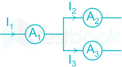
Currents through ammeters A2 and A3 in the figure are 1∠10° and 1∠70°, respectively. The reading of the ammeter A1 (rounded off to 3 decimal places) is _____ A.

29

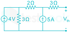
The Thevenin equivalent voltage, Vth, in V (rounded off to 2 decimal places) of the network shown below, is ________

30

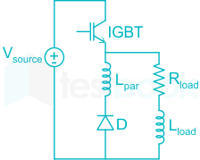
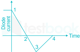
A double pulse measurement for an inductively loaded circuit controlled by the IGBT switch is carried out to evaluate the reverse recovery characteristics of the diode, D, represented approximately as a piecewise linear plot of current vs time at diode turn-off. Lpar is a parasitic inductance due to the wiring of the circuit, and is in series with the diode. The point on the plot (indicate your choice by entering 1, 2, 3 or 4) at which the IGBT experiences the highest current stress is _____


31

A single-phase, 4 kVA, 200 V/100 V, 50 Hz transformer with laminated CRGO steel core has rated no-load loss of 450 W. When the high-voltage winding is excited with 160 V, 40 Hz sinusoidal ac supply, the no-load losses are found to be 320 W. When the high-voltage winding of the same transformer is supplied from a 100 V, 25 Hz sinusoidal ac source, the no-load losses will be_________ W (rounded off to 2 decimal places).

32

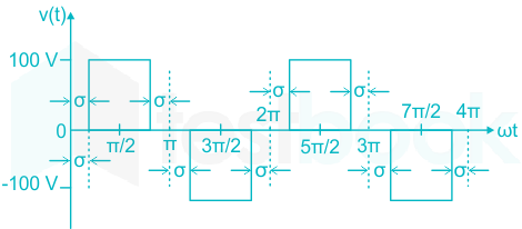
A single-phase inverter is fed from a 100 V dc source and is controlled using a quasi-square wave modulation scheme to produce an output waveform, v(t), as shown. The angle σ is adjusted to entirely eliminate the 3rd harmonic component from the output voltage. Under this condition, for v(t), the magnitude of the 5th harmonic component as a percentage of the magnitude of the fundamental component is _______ (rounded off to 2 decimal places). 

33

A single 50 Hz synchronous generator on droop control was delivering 100 MW power to a system. Due to increase in load, generator power had to be increased by 10 MW, as a result of which, system frequency dropped to 49.75 Hz. Further increase in load in the system resulted in a frequency of 49.25 Hz. At this condition, the power in MW supplied by the generator is _____  (rounded off to 2 decimal places).

34

Consider a negative unity feedback system with forward path transfer function G(s)=K(s+a)(sb)(s+c)G\left( s \right) = \frac{K}{{\left( {s + a} \right)\left( {s - b} \right)\left( {s + c} \right)}}, where K, a, b, c are positive real numbers. For a Nyquist path enclosing the entire imaginary axis and right half of the s-plane is the clockwise direction, the Nyquist plot of (1 + G(s)), encircles the origin (1 + G(s)) –plane once in the clockwise direction and never passes through this origin for a certain value of K. then, the number of poles of G(s)1+G(s)\frac{{G\left( s \right)}}{{1 + G\left( s \right)}} lying in the open right half of the s-plane is ______.

35

The cross-section of a metal-oxide-semiconductor structure is shown schematically. Starting from an uncharged condition, a bias of +3 V is applied to the gate contact with respect to the body contact. The charge inside the silicon dioxide layer is then measured to be +Q. The total charge contained within the dashed box shown, upon application of bias, expressed as a multiple of Q (absolute value in Coulombs, rounded off to the nearest integer) is
36

For real numbers, x and y with y = 3x2 + 3x + 1, the maximum and minimum value of y for x ∈ [-2, 0] are respectively, ______

  1. ((a))

    7 and 1/4

  2. ((b))

    7 and 1

  3. ((c))

    -2 and -1/2

  4. ((d))

    1 and 1/4

Show Answer
Answer: ((a))

7 and 1/4

Concept:

A point c in the domain of a function f at which either f'(c) = 0 or if f is nondifferentiable is called the critical point.
The slope of tangents at critical points are zero

Let f be a real valued function and c be an interior point in the domain of f such that f'(c)=0.
  • If f'(x) > 0 at every point close to left of c and f'(x) < 0 at every point right of c, then is a local maximum.
  • If f'(x) > 0 at every point close to right of c and f'(x) < 0 at every point left of c, then is a local minimum.
  • If f'(x) does not change sign as x increases or decreases, then such a point is called point of inflection.
<br>

Calculation:

y = 3x2 + 3x + 1

f'(x) = 6x + 3 = 0

x=12 \Rightarrow x = - \frac{1}{2}

f'’(x) = 6 > 0

Therefore, the point x=12x = - \frac{1}{2} is the point of minima

For global maximum and minimum values we have to consider the extreme points also along with critical points.

Means we have to calculate function 'y' value at -2 and 0 also.

f(x = -2) = 3 (-2)2 – 6 + 1 = 7   ------------------------(1)

f(x = 0) = 0 + 0 + 1 = 1       ______(2)

f(x=12)=3(12)2+3(12)+1=14f\left( {x = - \frac{1}{2}} \right) = 3{\left( { - \frac{1}{2}} \right)^2} + 3\left( { - \frac{1}{2}} \right) + 1 = \frac{1}{4}  --------------(3)

From (1), (2) and (3) we can observe that,

The maximum value of y = 7 and the minimum value at y = 1/4.

Hence, the maximum, and minimum values of y are 7 and 1/4.

37

The vector function expressed by

F=ax;(5yk1z)+ay(3z+k2x)+az(k3y4x)F = {a_x};\left( {5y - {k_1}z} \right) + {a_y}\left( {3z + {k_2}x} \right) + {a_z}\left( {{k_3}y - 4x} \right)

Represents a conservative field, where ax, ay, az are unit vectors along x, y and z directions, respectively. The values of constant k1, k2, k3 are given by:

  1. ((a))

    k1 = 3, k2 = 3, k3 = 7

  2. ((b))

    k1 = 3, k2 = 8, k3 = 5

  3. ((c))

    k1 = 4, k2 = 5, k3 = 3

  4. ((d))

    k1 = 0, k2 = 0, k3 = 0

Show Answer
Answer: ((c))

k1 = 4, k2 = 5, k3 = 3

Concept:

For a vector F = F1i + F2j + F3k

Div=.F=F1x+F2y+F3zDiv = \nabla .F = \frac{{\partial {F_1}}}{{\partial x}} + \frac{{\partial {F_2}}}{{\partial y}} + \frac{{\partial {F_3}}}{{\partial z}}

\(Curl = \nabla \times F = \left| {\begin{array}{*{20}{c}} i&j&k\ {\frac{\partial }{{\partial x}}}&{\frac{\partial }{{\partial y}}}&{\frac{\partial }{{\partial z}}}\ {{F_1}}&{{F_2}}&{{F_3}} \end{array}} \right|\)

For irrotational (or) conservative field ×F=0\nabla \times \vec F = 0 (or) Null Vector.

Calculation:

Given that,

F=a^x;(5yk1z)+a^y(3z+k2x)+a^z(k3y4x)\vec F = {\hat a_x};\left( {5y - {k_1}z} \right) + {\hat a_y}\left( {3z + {k_2}x} \right) + {\hat a_z}\left( {{k_3}y - 4x} \right) is a conservative field.

\(\left| {\begin{array}{*{20}{c}} {{{\hat a}_x}}&{{{\hat a}_y}}&{{{\hat a}_z}}\ {\frac{\partial }{{\partial x}}}&{\frac{\partial }{{\partial y}}}&{\frac{\partial }{{\partial z}}}\ {\left( {5y - {k_1}z} \right)}&{\left( {3z + {k_2}x} \right)}&{\left( {{k_3}y - 4x} \right){\rm{;}}} \end{array}} \right| = 0\)

a^x;(k33)a^y(;4+k1)+a^z(k25) \Rightarrow {\hat a_x};\left( {{{\rm{k}}_3} - 3} \right) - {\hat a_y}\left( {; - 4 + {{\rm{k}}_1}} \right) + {\hat a_z}\left( {{{\rm{k}}_2} - 5} \right)

k3 – 3 = 0 ⇒ k3 = 3

-4 + k1 = 0 ⇒ k1 = 4

k2 – 5 = 0 ⇒ k2 = 5

The required values are: k1 = 4, k2 = 5, k3 = 3

38

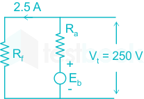
A 250 V dc shunt motor has an armature resistance of 0.2 Ω and a field resistance of 100 Ω. When the motor is operated on no-load at rated voltage, it draws an armature current of 5 A and runs at 1200 rpm. When a load is coupled to the motor, it draws total line current of 50 A at rated voltage, with a 5 % reduction in the air-gap flux due to armature reaction. Voltage drop across the brushes can be taken as 1 V per brush under all operating conditions. The speed of the motor, in rpm, under this loaded condition, is closest to: 

  1. ((a))

    1200

  2. ((b))

    1000

  3. ((c))

    1220

  4. ((d))

    900

Show Answer
Answer: ((c))

1220

Concept:

In a DC shunt motor, the back emf is given by

Eb=NPϕZ60A{E_b} = \frac{{NP\phi Z}}{{60A}}

Where N is the speed

ϕ is the flux per pole

P is the number of poles

Z is the number of conductors

EbNϕ{E_b} \propto \frac{N}{\phi }

N2N1=Eb2Eb1×ϕ1ϕ2 \Rightarrow \frac{{{N_2}}}{{{N_1}}} = \frac{{{E_{b2}}}}{{{E_{b1}}}} \times \frac{{{\phi _1}}}{{{\phi _2}}}

Calculation:

At no-load condition:

Armature current, Ia1 = 5A

No-load speed, N1 = 1200 rpm,

Brush drop = 1 V per brush

Total brush drop = 2V

Eb1 = V – Ia1 Ra – Brush drop

= 250 – 5 × 0.2 – 2 = 247 V

At load condition:

Ia2 = IL – If = 47.5 A

ϕ2 = 0.95 ϕ1

Eb2 = V – Ia2 Ra – Brush drop

= 250 – 47.5 × 0.2 – 2 = 238.5 V

Now, N2N1=Eb2Eb1×ϕ1ϕ2\frac{{{N_2}}}{{{N_1}}} = \frac{{{E_{b2}}}}{{{E_{b1}}}} \times \frac{{{\phi _1}}}{{{\phi _2}}}

N21200=238.5247×ϕ10.95ϕ1=1.0164 \Rightarrow \frac{{{N_2}}}{{1200}} = \frac{{238.5}}{{247}} \times \frac{{{\phi _1}}}{{0.95{\phi _1}}} = 1.0164

N2 = 1200 × 1.0164 = 1219.688

39

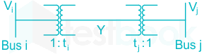
Two buses, i and j, are connected with a transmission line of admittance Y, at the two ends of which there are ideal transformers with turns ratios as shown. Bus admittance matrix for the system is:

  1. ((a))

    \(\left[ {\begin{array}{*{20}{c}} { - {t_i}{t_j}Y}&{t_j^2Y}\ {t_i^2}Y&{ - {t_i}{t_j}Y} \end{array}} \right]\)

  2. ((b))

    \(\left[ {\begin{array}{*{20}{c}} {{t_i}{t_j}Y}&{ - t_j^2Y}\ { - t_i^2Y}&{{t_i}{t_j}Y} \end{array}} \right]\)

  3. ((c))

    \(\left[ {\begin{array}{*{20}{c}} {t_i^2Y}&{ - {t_i}{t_j}Y}\ { - {t_i}{t_j}Y}&{t_j^2Y} \end{array}} \right]\)

  4. ((d))

    \(\left[ {\begin{array}{*{20}{c}} {{t_i}{t_j}Y}&{ - {{\left( {{t_i} - {t_j}} \right)}^2}Y}\ { - {{\left( {{t_i} - {t_j}} \right)}^2}Y}&{{t_i}{t_j}Y} \end{array}} \right]\)

Show Answer
Answer: ((c))

\(\left[ {\begin{array}{*{20}{c}} {t_i^2Y}&{ - {t_i}{t_j}Y}\ { - {t_i}{t_j}Y}&{t_j^2Y} \end{array}} \right]\)

Bus admittance matrix:

\(\left[ {\begin{array}{{20}{c}} {{{\rm{I}}{\rm{i}}}}\ {{{\rm{I}}{\rm{j}}}} \end{array}} \right] = \left[ {\begin{array}{{20}{c}} {{{\rm{Y}}{{\rm{ii}}}}}&{{{\rm{Y}}{{\rm{ij}}}}}\ {{{\rm{Y}}{{\rm{ji}}}}}&{{{\rm{Y}}{{\rm{jj}}}}} \end{array}} \right]\left[ {\begin{array}{*{20}{c}} {{{\rm{V}}{\rm{i}}}}\ {{{\rm{V}}{\rm{j}}}} \end{array}} \right]\)

Two buses, i and j, are connected with a transmission line of admittance Y, at the two ends of which there are ideal transformers with turns ratios \(1:{{\rm{t}}{\rm{i}}}{\rm{;}}& {\rm{;}}1:{{\rm{t}}{\rm{j}}}\).

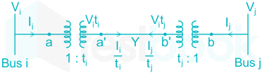
From the circuit shown above,

\(\frac{{{{\rm{I}}{\rm{i}}}}}{{{{\rm{t}}{\rm{i}}}}} = \left( {{{\rm{V}}{\rm{i}}}{{\rm{t}}{\rm{i}}} - {{\rm{V}}{\rm{j}}}{{\rm{t}}{\rm{j}}}} \right){\rm{Y}}\)

\({{\rm{I}}{\rm{i}}} = \left( {{{\rm{t}}{\rm{i}}}^2.{\rm{Y}}} \right){{\rm{V}}{\rm{i}}} - \left( { - {{\rm{t}}{\rm{i}}}{{\rm{t}}{{\rm{j}}.}}{\rm{Y}}} \right){{\rm{V}}{\rm{j}}}\)      ---(1)

Also, \(\frac{{{{\rm{I}}{\rm{j}}}}}{{{{\rm{t}}{\rm{j}}}}} = \left( {{{\rm{V}}{\rm{j}}}{{\rm{t}}{\rm{j}}} - {{\rm{V}}{\rm{i}}}{{\rm{t}}{\rm{i}}}} \right){\rm{Y}}\)

\({{\rm{I}}{\rm{j}}} = \left( { - {{\rm{t}}{\rm{i}}}{{\rm{t}}{{\rm{j}}.}}{\rm{Y}}} \right){{\rm{V}}{\rm{i}}} - {{\rm{V}}{\rm{j}}}({{\rm{t}}{\rm{j}}}^2.{\rm{Y}})\)      ---(2)

From equation (1) and (2), we get,

\(\left[ {{{\rm{Y}}{{\rm{Bus}}}}} \right] = \left[ {\begin{array}{*{20}{c}} {{{\rm{t}}{\rm{i}}}^2.{\rm{Y}}}&{ - {{\rm{t}}{\rm{i}}}{{\rm{t}}{{\rm{j}}.}}{\rm{Y}}}\ { - {{\rm{t}}{\rm{i}}}{{\rm{t}}{{\rm{j}}.}}{\rm{Y}}}&{{{\rm{t}}_{\rm{j}}}^2.{\rm{Y}}} \end{array}} \right]\)

40

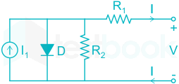
Consider the diode circuit shown below. The diode, D, obeys the current-voltage characteristic ID=IS(exp(VDnVT;)1){I_D} = {I_S}\left( {\exp \left( {\frac{{{V_D}}}{{n{V_T};}}} \right) - 1} \right), where n > 1, VT > 0, VD is the voltage across the diode and ID is the current through it. The circuit is biased so that voltage, V > 0 and current, I < 0. If you had to design this circuit to transfer maximum power from the current source (I1) to a resistive load (not shown) at the output, what values of R1 and R2 would you choose?

  1. ((a))

    Large R1 and large R2

  2. ((b))

    Small R1 and small R2

  3. ((c))

    Large R1 and small R2

  4. ((d))

    Small R1 and large R2

Show Answer
Answer: ((d))

Small R1 and large R2

Concept:

By using the voltage division rule,

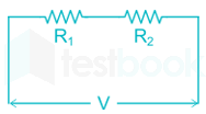
The voltage applied across the resistor R1 is VR1=V(R1)R1+R2{V_{R1}} = \frac{{V\left( {{R_1}} \right)}}{{{R_1} + {R_2}}}

The voltage applied across the resistor R2 is VR2=V(R2)R1+R2{V_{R2}} = \frac{{V\left( {{R_2}} \right)}}{{{R_1} + {R_2}}}

Explanation:

VD is the voltage across the diode, then by using voltage division

VD=V×R2R1+R2{V_D} = V \times \frac{{{R_2}}}{{{R_1} + {R_2}}}

If R2 is large, VD is high

If R1 is small, then VD = V.

Therefore, to transfer maximum power, R2 should be very large and R1 should be very small.

41

A non-ideal diode is biased with a voltage of -0.03 V, and a diode current of I1 is measured. The thermal voltage is 26 mV and the ideality factor for the diode is 15/13. The voltage, in V, at which the measured current increases to 1.5 I1 is closest to:

  1. ((a))

    -0.02

  2. ((b))

    -0.09

  3. ((c))

    -1.50

  4. ((d))

    -4.50

Show Answer
Answer: ((b))

-0.09

Concept:

The current across a diode (I) is given by:

\(I={{I}{0}}\left( {{e}^{\frac{{{V}{D}}}{\eta {{V}_{T~}}}}}-1 \right)\)

VD = Applied Voltage.

VT = Thermal Voltage

η = Ideality factor.

Calculation:

\({{\rm{I}}{\rm{D}}} = {{\rm{I}}0}\left[ {{{\rm{e}}^{\frac{{{{\rm{V}}{\rm{D}}}}}{{{\rm{\eta }}{{\rm{V}}{\rm{T}}}}}}} - 1} \right]\)

ID1 = I1, ID2 = 1.5I1

\({{\rm{V}}{\rm{D}}} = - 0.03,;{\rm{\eta }} = \frac{{15}}{{13}},;{{\rm{V}}{\rm{T}}} = 26{\rm{mV}}\)

η×VT=1513×26×103=0.03{\rm{\eta }} \times {{\rm{V}}_{\rm{T}}} = \frac{{15}}{{13}} \times 26 \times {10^{ - 3}} = 0.03

\( \Rightarrow \frac{{{{\rm{I}}{{\rm{D}}2}}}}{{{{\rm{I}}{{\rm{D}}1}}}} = \frac{{{{\rm{e}}^{\frac{{{{\rm{V}}{{\rm{D}}2}}}}{{{\rm{\eta }}{{\rm{V}}{\rm{T}}}}}}} - 1}}{{{{\rm{e}}^{\frac{{{{\rm{V}}{{\rm{D}}1}}}}{{{\rm{\eta }}{{\rm{V}}{\rm{T}}}}}}} - 1}}\)

\( \Rightarrow \frac{{1.5 \times {{\rm{I}}_1}}}{{{{\rm{I}}1}}} = \frac{{{{\rm{e}}^{\frac{{{{\rm{V}}{{\rm{D}}2}}}}{{0.03}}}} - 1}}{{{{\rm{e}}^{\frac{{ - 0.03}}{{0.03}}}} - 1}}\)

1.5×0.6321=eVD20.031 \Rightarrow 1.5 \times - 0.6321 = {{\rm{e}}^{\frac{{{{\rm{V}}_{{\rm{D}}2}}}}{{0.03}}}} - 1

0.9481+1=eVD20.03 \Rightarrow - 0.9481 + 1 = {{\rm{e}}^{\frac{{{{\rm{V}}_{{\rm{D}}2}}}}{{0.03}}}}

0.0518=eVD20.03 \Rightarrow 0.0518 = {{\rm{e}}^{\frac{{{{\rm{V}}_{{\rm{D}}2}}}}{{0.03}}}}

ln0.0518=VD20.03 \Rightarrow \ln 0.0518 = \frac{{{{\rm{V}}_{{\rm{D}}2}}}}{{0.03}}

VD2=2.9599×0.03=0.09 \Rightarrow {{\rm{V}}_{{\rm{D}}2}} = - 2.9599 \times 0.03 = - 0.09

42

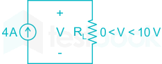
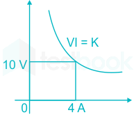
A benchtop dc power supply acts as an ideal 4 A current source as long as its terminal voltage is below 10 V. Beyond this point, it begins to behave as an ideal 10 V voltage source for all load currents going down to 0 A. When connected to an ideal rheostat, find the load resistance value at which maximum power is transferred, and the corresponding load voltage and current.

  1. ((a))

    Short, ∞ A, 10 V

  2. ((b))

    Open, 4 A, 0 V

  3. ((c))

    2.5 Ω, 4 A, 10 V

  4. ((d))

    2.5 Ω, 4 A, 5 V

Show Answer
Answer: ((c))

2.5 Ω, 4 A, 10 V

Dc power supply acts as an ideal 4 A current source as long as its terminal voltage is below 10 V.

Beyond the above point, it begins to behave as an ideal 10 V voltage source for all load currents going down to 0 A.

Now, the characteristics are as shown below.

So, 42 × RL = 40 W

⇒ RL = 2.5 Ω

So, the answer will be 2.5 Ω, 4 A, 10 V.

Alternate method:

If supply acts as a 4 A current source,

V = 4 × R, P = 42 × R

Vmax = 10 V, Rmin = 10/4 = 2.5 Ω

Pmax = 16 × 2.5 = 40 W.

Now, if supply acts as 10 V source and R > 2.5;Ω2.5;{\rm{\Omega }}

I=10R,;P=102R{\rm{I}} = \frac{{10}}{{\rm{R}}},{\rm{;P}} = \frac{{{{10}^2}}}{{\rm{R}}}

Pmax=1022.5=40;W{{\rm{P}}_{{\rm{max}}}} = \frac{{{{10}^2}}}{{2.5}} = 40{\rm{;W}}

R = 2.5 Ω, I = 4 A, V = 10 V.

43

The static electric field inside a dielectric medium with relative permittivity εr = 2.25, expressed in cylindrical coordinate system is given by the following expression

E=ar;2r+aϕ(3r)+az;6E = {a_r};2r + {a_\phi }\left( {\frac{3}{r}} \right) + {a_z};6

Where ar, aϕ, az are unit vectors along r, ϕ and z directions, respectively. If the above expression represents a valid electrostatic field inside the medium, then the volume charge density associated with this field in terms of free space permittvity, ε0, in SI units is given by

  1. ((a))

    3 ε0

  2. ((b))

    4 ε0

  3. ((c))

    5 ε0

  4. ((d))

    9 ε0

Show Answer
Answer: ((d))

9 ε0

Concept:

From Gauss’ Law, the volume charge density is given by

ρν=.D=.ε0εrE{\rho _\nu } = \nabla .\vec D = \nabla .{{\rm{\varepsilon }}_0}{{\rm{\varepsilon }}_r}\vec E

In Cylindrical coordinate system, \(\nabla .\vec E = \left[ {\frac{\partial }{{\partial r}}\left( {{\rm{r}}{{\rm{E}}{\rm{r}}}} \right) + \frac{\partial }{{\partial \phi }}{{\rm{E}}\phi } + \frac{\partial }{{\partial \phi }}\left( {{\rm{r}}{{\rm{E}}_{\rm{z}}}} \right)} \right]\)

Calculation:

Given that,

Relative permittivity, εr = 2.25

E=;2rr^+(3r)ϕ^+;6z^\vec E = ;2r\hat r + \left( {\frac{3}{r}} \right)\hat \phi + ;6\hat z

ρν=ε0εr.E{\rho _\nu } = {{\rm{\varepsilon }}_0}{{\rm{\varepsilon }}_r}\nabla .\vec E

=ε0εr1r[r(r.2r)+(3r)+(r.6)] = {{\rm{\varepsilon }}_0}{{\rm{\varepsilon }}_r}\frac{1}{r}\left[ {\frac{\partial }{{\partial r}}\left( {{\rm{r}}.2{\rm{r}}} \right) + \frac{\partial }{{\partial \emptyset }}\left( {\frac{3}{r}} \right) + \frac{\partial }{{\partial \emptyset }}\left( {{\rm{r}}.6} \right)} \right]

=ε0×2.25×1r[4r+0+0]= {{\rm{\varepsilon }}_0} \times 2.25 \times \frac{1}{r}\left[ {4r + 0 + 0} \right]

ρν=ε0×2.25×4=9ε0{\rho _\nu } = {{\rm{\varepsilon }}_0} \times 2.25 \times 4 = 9{\varepsilon _0}

44

Consider a permanent magnet dc (PMDC) motor which is initially at rest. At t = 0, a dc voltage of 5 V is applied to the motor. Its speed monotonically increases from 0 rad/s to 6.32 rad/s in 0.5 s and finally settles to 10 rad/s. Assuming that the armature inductance of the motor is negligible, the transfer function for the motor is

  1. ((a))

    100.5s+1\frac{{10}}{{0.5s + 1}}

  2. ((b))

    20.5s+1\frac{2}{{0.5s + 1}}

  3. ((c))

    2s+0.5\frac{2}{{s + 0.5}}

  4. ((d))

    10s+0.5\frac{{10}}{{s + 0.5}}

Show Answer
Answer: ((b))

20.5s+1\frac{2}{{0.5s + 1}}

The standard transfer function is,

C(s)R(s)=T.F=K1+Ts\frac{{C\left( s \right)}}{{R\left( s \right)}} = T.F = \frac{K}{{1 + Ts}}

Given that, DC input = 5 V

R(s)=5s \Rightarrow R\left( s \right) = \frac{5}{s}

T = 0.5 s

Steady state speed = 10 rad/sec.

Now we have,

C(s)=5s×K1+0.5sC\left( s \right) = \frac{5}{s} \times \frac{K}{{1 + 0.5s}}

Now according to final value theorem,

lims0[sC(s)]=10\mathop {\lim }\limits_{s \to 0} \left[ {sC\left( s \right)} \right] = 10

lims0[sC(s)]=5×K=10K=2\mathop {\lim }\limits_{s \to 0} \left[ {sC\left( s \right)} \right] = 5 \times K = 10 \Rightarrow K = 2

Now, the required transfer function is,

T.F=K1+Ts=21+0.5sT.F = \frac{K}{{1 + Ts}} = \frac{2}{{1 + 0.5s}}

45

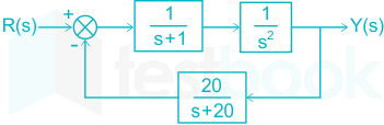
Which of the following options is correct for the system shown below?

  1. ((a))

    4th order and stable

  2. ((b))

    3rd order and stable

  3. ((c))

    4th order and unstable

  4. ((d))

    3rd order and unstable

Show Answer
Answer: ((c))

4th order and unstable

From the block diagram,

G(s)=1s2(s+1)G\left( s \right) = \frac{1}{{{s^2}\left( {s + 1} \right)}}

H(s)=20(s+20)H\left( s \right) = \frac{{20}}{{\left( {s + 20} \right)}}

As the given feedback is negative, the transfer function of the closed loop system is

Y(s)R(s)=G(s)1+G(s)H(s)\frac{{Y\left( s \right)}}{{R\left( s \right)}} = \frac{{G\left( s \right)}}{{1 + G\left( s \right)H\left( s \right)}}

=1s2(s+1)1+1s2(s+1)20(s+20) = \frac{{\frac{1}{{{s^2}\left( {s + 1} \right)}}}}{{1 + \frac{1}{{{s^2}\left( {s + 1} \right)}}\frac{{20}}{{\left( {s + 20} \right)}}}}

=s+20s2(s+1)(s+20)+20 = \frac{{s + 20}}{{{s^2}\left( {s + 1} \right)\left( {s + 20} \right) + 20}}

=s+20s4+21s3+20s2+20 = \frac{{s + 20}}{{{s^4} + 21{s^3} + 20{s^2} + 20}}

The denominator of the above transfer function has the highest degree of 4. Therefore, the order of the system is 4.

The coefficient of ‘s’ term is zero in the characteristic equation (denominator of above transfer function). Therefore, the system is unstable.

46

Consider a negative unity feedback system with the forward path transfer function  s2+s+1s3+2s2+2s+K\frac{{{s^2} + s + 1}}{{{s^3} + 2{s^2} + 2s + K}}, where K is a positive real number. The value of K for which the system will have some of its poles on the imaginary axis is ________

  1. ((a))

    9

  2. ((b))

    8

  3. ((c))

    7

  4. ((d))

    6

Show Answer
Answer: ((b))

8

Concept:

The characteristic equation for a given open-loop transfer function G(s) is

1 + G(s) H(s) = 0

According to the Routh tabulation method,

  • The system is said to be stable if there are no sign changes in the first column of Routh array
  • The number of poles lies on the right half of s plane = number of sign changes
  • The system has the poles on the imaginary axis when the s1 row becomes zero in the Routh array.


Calculation:

Give forward path transfer function is

G(s)=s2+s+1s3+2s2+2s+KG\left( s \right) = \frac{{{s^2} + s + 1}}{{{s^3} + 2{s^2} + 2s + K}}

As the feedback is unity, H(s) = 1

The characteristic equation: 1+ G(s) H(s) = 0

1+s2+s+1s3+2s2+2s+K=01 + \frac{{{s^2} + s + 1}}{{{s^3} + 2{s^2} + 2s + K}} = 0

⇒ s3 + 3 s2 + 3s + (K + 1) = 0

By applying Routh tabulation method,

\(\begin{array}{{20}{c}} {{s^3}}\ {{s^2}}\ {{s^1}}\ {{s^0}} \end{array}\left| {\begin{array}{{20}{c}} 1&3\ 3&{1 + K}\ {9 - \left( {1 + K} \right)}&0\ {1 + K}&{} \end{array}} \right.\)

For the system to have poles on the imaginary axis,

9 – (1 + K) = 0

K = 8

47

Suppose for input x(t) a linear time-invariant system with impulse response h(t) produces output y(t), so that x(t) * h(t) = y(t). Further, if |x(t)| * |h(t)| = z(t), which of the following statements is true?

  1. ((a))

    For all t ∈ (-∞, ∞), z(t) ≤ y(t)

  2. ((b))

    For some but not all t ∈ (-∞, ∞), z(t) ≤ y(t)

  3. ((c))

    For all t ∈ (-∞, ∞), z(t) ≥ y(t)  

  4. ((d))

    For some but not all t ∈ (-∞, ∞), z(t) ≥ y(t)  

Show Answer
Answer: ((c))

For all t ∈ (-∞, ∞), z(t) ≥ y(t)  

Concept:

Let the input is x(t), the output is y(t) and the impulse response is h(t).

The convolution is given by

y(t) = x(t) * y(t)

\(y\left( t \right) = \mathop \smallint \limits_{ - \infty }^\infty x\left( \tau \right)h\left( {t - \tau } \right)d\tau \)

Explanation:

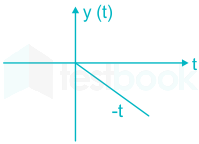
y(t) = x(t) * h(t)

Consider the signal x(t) = u(t) & h(t) = -u(t) for input x(t) with impulse response h(t)

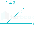
y(t) = u(t) * (-u(t)) = -r(t)

For input |x(t)| with impulse response |h(t)|

z(t) = |u(t)| * |-u(t)| = r(t)

Hence,

Z(t) ≥ y(t) for all value of t.

48

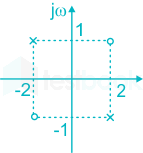
The causal realization of a system transfer function H(s) having poles at (2, -1), (-2, 1) and zeroes at (2, 1), (-2, -1) will be

  1. ((a))

    stable, real, all pass

  2. ((b))

    unstable, complex, all pass

  3. ((c))

    unstable, real, high pass

  4. ((d))

    stable, complex, low pass

Show Answer
Answer: ((b))

unstable, complex, all pass

Given that,

Poles = (2, -1) and (-2, 1)

Zeros = (2, 1), (-2, -1)

Now, drawing the Poles and Zeros to the Real and Imaginary axis-

The transfer function can be written as

H(s)=[s(2+j)][s(2j)][s(2+j)][s(2+j)]H\left( s \right) = \frac{{\left[ {s - \left( {2 + j} \right)} \right]\left[ {s - \left( { - 2 - j} \right)} \right]}}{{\left[ {s - \left( {2 + j} \right)} \right]\left[ {s - \left( { - 2 + j} \right)} \right]}}

H(s)=s234js23+4jH\left( s \right) = \frac{{{s^2} - 3 - 4j}}{{{s^2} - 3 + 4j}}

Observations:

  • Magnitude of H(jω) = 1. Therefore, the given system is an all-pass filter.
  • Since one pole on the RHS, the system is unstable.
  • Since the pole does not have complex conjugate poles and zeros present, the system is complex.
49

Which of the following options is true for a linear time-invariant discrete time system that obeys the difference equation?

y[n] – ay[n - 1] = b0x[n] – b1x[n - 1]

  1. ((a))

    y[n] is unaffected by the values of x [n - k]; k > 2

  2. ((b))

    The system is necessarily causal

  3. ((c))

    The system impulse response is non-zero at infinitely many instants

  4. ((d))

    When x[n] = 0, n < 0, the function y[n]; n > 0 is solely determined by the function x[n]

Show Answer
Answer: ((c))

The system impulse response is non-zero at infinitely many instants

Given difference equation is,

y[n] – a y[n - 1] = b0 x[n] – b1 x[n - 1]

By applying Z-transform,

Y(z) – az–1 Y(z) = b0X(z) – b1z–1 X(z)

H(z)=Y(z)X(z)=b0b1Z11aZ1H\left( z \right) = \frac{{Y\left( z \right)}}{{X\left( z \right)}} = \frac{{{b_0} - {b_1}{Z^{ - 1}}}}{{1 - a{Z^{ - 1}}}}

By taking right sided Inverse Z- Transform-

h(n) = b0an u(n) – b1an-1 u(n – 1)

By taking left sided Inverse Z- Transform-

h(n) = -b0an u(-n-1) – b1an-1 u(-n)

Thus, the system is not necessarily causal.

The impulse response is non-zero at infinitely many instants.

50

Let ar, aϕ, and az be unit vectors along r, ϕ and z directions, respectively in the cylindrical coordinate system. For the electric flux density given by D = (ar 15 + aϕ 2r - az 3rz)  Coulomb/m2, the total electric flux, in Coulomb, emanating from the volume enclosed by a solid cylinder of radius 3 m and height 5 m oriented along the z-axis with its base at the origin is:

  1. ((a))

    54 π 

  2. ((b))

    90 π

  3. ((c))

    108 π

  4. ((d))

    180 π

Show Answer
Answer: ((d))

180 π

Divergence theorem:

It states that the surface integral of a vector field over a closed surface, which is called the flux through the surface, is equal to the volume integral of the divergence over the region inside the surface.

ψ=!!!!!D.ds=(Δ.D)dv\psi =\mathop{{\int!!!!!\int}\mkern-21mu \bigcirc} \vec{D}.ds= \left( \iiint{\overrightarrow{\Delta }}.\vec{D} \right)dv

.D=1rr(r.Dr)+1rDϕϕ+Dzz\vec \nabla .\vec D = \frac{1}{r}\frac{\partial }{{\partial r}}\left( {r.{D_r}} \right) + \frac{1}{r}\frac{{\partial {D_\phi }}}{{\partial \phi }} + \frac{{\partial {D_z}}}{{\partial z}}

Calculation:

Given that, D = (ar 15 + aϕ 2r - az 3rz) 

(.D)=1rr(r.15)+1rϕ(2r)+z(3rz)=15r3r\left( {\vec \nabla .\vec D} \right) = \frac{1}{r}\frac{\partial }{{\partial r}}\left( {r.15} \right) + \frac{1}{r}\frac{\partial }{{\partial \phi }}\left( {2r} \right) + \frac{\partial }{{\partial z}}\left( { - 3rz} \right) = \frac{{15}}{r} - 3r

Now, by using Divergence Theorem-

(.D)dv=(15r3r).rdrdϕdz\iiint{\left( \vec{\nabla }.\vec{D} \right)}dv=\iiint{\left( \frac{15}{r}-3r \right).rdrd\phi dz}

=15drdϕdz3r2drdϕdz=\iiint{15drd\phi dz-}\iiint{3{{r}^{2}}drd\phi dz}

\( = 15\mathop \smallint \nolimits_{r = 0}^3 dr\mathop \smallint \nolimits_{\phi = 0}^{2\pi } d\phi \mathop \smallint \nolimits_{z = 0}^5 dz - 3\mathop \smallint \nolimits_{\rho = 0}^3 {r^2}d\rho \mathop \smallint \nolimits_{\phi = 0}^{2\pi } d\phi \mathop \smallint \nolimits_{z = 0}^5 dz\)

= 45 (10π) – 27 (10π) = 180π

51

A stable real linear time-invariant system with single pole at p, has a transfer function H(s)=s2+100spH\left( s \right) = \frac{{{s^2} + 100}}{{s - p}} with a dc gain of 5. The smallest positive frequency, in rad/s at unity gain is closest to:

  1. ((a))

    8.84

  2. ((b))

    11.08

  3. ((c))

    78.13

  4. ((d))

    122.87

Show Answer
Answer: ((a))

8.84

Given the transfer function, H(s)=s2+100spH\left( s \right) = \frac{{{s^2} + 100}}{{s - p}}

dc gain = 5

To find the DC gain, put s = 0 in the above transfer function.

100p=5p=20\frac{{100}}{{ - p}} = 5 \Rightarrow p = - 20

Now, the transfer function becomes

H(s)=s2+100s+20H\left( s \right) = \frac{{{s^2} + 100}}{{s + 20}}

Put the value of s = jω in transfer function

H(jω)=ω2+100jω+20H\left( {j\omega } \right) = \frac{{ - {\omega ^2} + 100}}{{j\omega + 20}}

H(jω)=ω2+100(ω2+400)\left| {H\left( {j\omega } \right)} \right| = \frac{{ - {\omega ^2} + 100}}{{\sqrt {\left( {{\omega ^2} + 400} \right)} }}

We need to find the frequency ω at |H(jω)| = 1

ω2+100(ω2+400)=1 \Rightarrow \frac{{ - {\omega ^2} + 100}}{{\sqrt {\left( {{\omega ^2} + 400} \right)} }} = 1

(ω2+100)2=ω2+400 \Rightarrow {\left( { - {\omega ^2} + 100} \right)^2} = {\omega ^2} + 400

Let ω2 = t, now the above equation becomes

(100 – t)2 = t + 400

⇒ 10000 + t2 – 200t = t + 400

⇒ t2 – 201t + 9600 = 0

⇒ t = 122.86 and 78.13

⇒ ω = 11.08 and 8.84

The smallest possible frequency = 8.84 rad/sec

52

The number of purely real elements in a lower triangular representation of the given 3 × 3 matrix obtained through the given decomposition is _____

\(\left[ {\begin{array}{{20}{c}} 2&3&3\ 3&2&1\ 3&1&7 \end{array}} \right] = \left[ {\begin{array}{{20}{c}} {{a_{11}}}&0&0\ {{a_{12}}}&{{a_{22}}}&0\ {{a_{13}}}&{{a_{23}}}&{{a_{33}}} \end{array}} \right]{\left[ {\begin{array}{*{20}{c}} {{a_{11}}}&0&0\ {{a_{12}}}&{{a_{22}}}&0\ {{a_{13}}}&{{a_{23}}}&{{a_{33}}} \end{array}} \right]^T}\)

  1. ((a))

    7

  2. ((b))

    6

  3. ((c))

    8

  4. ((d))

    9

Show Answer
Answer: ((a))

7

Calculation:

\(\left[ {\begin{array}{{20}{c}} 2&3&3\ 3&2&1\ 3&1&7 \end{array}} \right] = \left[ {\begin{array}{{20}{c}} {{a_{11}}}&0&0\ {{a_{12}}}&{{a_{22}}}&0\ {{a_{13}}}&{{a_{23}}}&{{a_{33}}} \end{array}} \right]{\left[ {\begin{array}{*{20}{c}} {{a_{11}}}&0&0\ {{a_{12}}}&{{a_{22}}}&0\ {{a_{13}}}&{{a_{23}}}&{{a_{33}}} \end{array}} \right]^T}\)

\(\left[ {\begin{array}{{20}{c}} 2&3&3\ 3&2&1\ 3&1&7 \end{array}} \right] = \left[ {\begin{array}{{20}{c}} {{a_{11}}}&0&0\ {{a_{12}}}&{{a_{22}}}&0\ {{a_{13}}}&{{a_{23}}}&{{a_{33}}} \end{array}} \right]\left[ {\begin{array}{*{20}{c}} {{a_{11}}}&{{a_{12}}}&{{a_{13}}}\ 0&{{a_{22}}}&{{a_{23}}}\ 0&0&{{a_{33}}} \end{array}} \right]\)

\(\left[ {\begin{array}{{20}{c}} 2&3&3\ 3&2&1\ 3&1&7 \end{array}} \right] = \left[ {\begin{array}{{20}{c}} {{a_{11}^2}}&{{a_{11}}{a_{12}}}&{{a_{11}}{a_{13}}}\ {{a_{11}}{a_{12}}}&{a_{12}^2 + a_{22}^2}&{{a_{12}}{a_{13}} + {a_{22}}{a_{23}}}\ {{a_{11}}{a_{13}}}&{{a_{12}}{a_{13}} + {a_{22}}{a_{23}}}&{a_{13}^2 + a_{23}^2 + a_{33}^2} \end{array}} \right]\)

By comparing on both sides,

a211 = 2

a11 a12 = 3 ⇒ a12 = 3/√2

a11 a13 = 3 ⇒ a13 = 3/√2

a122+a222=2a_{12}^2 + a_{22}^2 = 2

(32)2+a222=2a22=j1.58 {\left( {\frac{3}{\sqrt2}} \right)^2} + a_{22}^2 = 2 \Rightarrow {a_{22}} = {j}{1.58}

a12 a13 + a22 a23 = 1

(32)(32)+(j1.58)a23=1a23=j2.21\left( {\frac{3}{\sqrt2}} \right)\left( {\frac{3}{\sqrt2}} \right) + \left( {{j}{1.58}} \right){a_{23}} = 1 \Rightarrow {a_{23}} = j{2.21}

a132+a232+a332=7a_{13}^2 + a_{23}^2 + a_{33}^2 = 7

(32)2+(j2.21)2+a332=7{\left( {\frac{3}{\sqrt2}} \right)^2} + {\left( {j{2.21}} \right)^2} + a_{33}^2 = 7

a332=792+4.88=7.38a33=7.38a_{33}^2 = 7 - \frac{9}{2} + 4.88 = 7.38 \Rightarrow {a_{33}} = \sqrt{7.38}

Now the lower triangular representation of the given 3 × 3 matrices obtained through the given decomposition becomes

\(\left[ {\begin{array}{{20}{c}} 2&3&3\ 3&2&1\ 3&1&7 \end{array}} \right] = \left[ {\begin{array}{{20}{c}} \sqrt2&0&0\ {\frac{3}{\sqrt2}}&{j{1.58}}&0\ {\frac{3}{\sqrt2}}&{j{2.21}}&{\sqrt{7.38} } \end{array}} \right]{ \left[ {\begin{array}{*{20}{c}} \sqrt2&0&0\ {\frac{3}{\sqrt2}}&{j{1.58}}&0\ {\frac{3}{\sqrt2}}&{j{2.21}}&{\sqrt{7.38} } \end{array}} \right]^T}\)

Therefore, the number of purely real elements = 7

53

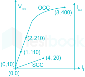
The figure below shows the per-phase Open Circuit Characteristics (measured in V) and Short Circuit Characteristics (measured in A) of a 14 kVA, 400 V, 50 Hz, 4-pole, 3-phase, delta connected alternator, driven at 1500 rpm. The field current, If is measured in A. Readings taken are marked as respective (x, y) coordinates in the figure. Ratio of the unsaturated and saturated synchronous impedances Zs(unsat) /Zs(sat) of the alternator is closest to:

  1. ((a))

    2.100

  2. ((b))

    2.025

  3. ((c))

    2.000

  4. ((d))

    1.000

Show Answer
Answer: ((a))

2.100

From the given OCC and SCC curves,

IfVOC (OCC)ISC (SCC)ZS(unsat) (If constant)ZS(sat) (If constant)
2 A210 V10 A210/10 = 21 Ω
4 A20 A
8 A400 V40 A400/40 =10 Ω


Synchronous impedance is,

Zs=;VocIsc{Z_s} = ;\frac{{{V_{oc}}}}{{{I_{sc}}}} at If = constant

Unsaturated synchronous impedance can be calculated at If = 2 A

Zs(unsat)=21010=21;Ω{Z_{s\left( {unsat} \right)}} = \frac{{210}}{{10}} = 21;{\rm{\Omega }}

Saturated synchronous impedance can be calculated at If = 8 A

Zs(sat)=;40040=10;Ω{Z_{s\left( {sat} \right)}} = ;\frac{{400}}{{40}} = 10;{\rm{\Omega }}

The ratio of the unsaturated and saturated synchronous impedances is

Zs(unsat)Zs(sat)=2110=2.1;Ω\frac{{{Z_{s\left( {unsat} \right)}}}}{{{Z_{s\left( {sat} \right)}}}} = \frac{{21}}{{10}} = 2.1;{\rm{\Omega }}

54

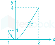
Let ax and ay be unit vectors along x and y directions, respectively. A vector function is given by

F = ax y - ay x

The line integral of above function

\(\mathop \smallint \nolimits_C F \cdot dl\)

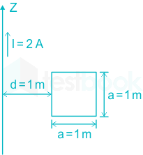
Along the curve C, which follows the parabola y = x2 as shown below is ______ (rounded off to 2 decimal places)

55

A resistor and a capacitor are connected in series to a 10 V dc supply through a switch. The switch is closed at t = 0, and the capacitor voltage is found to cross 0 V at t = 0.4τ, where τ is the circuit time constant. The absolute value of percentage change required in the initial capacitor voltage if the zero crossing has to happen at t = 0.2τ is _______  (rounded off to 2 decimal places).

56

A cylindrical rotor synchronous generator with constant real power output and constant terminal voltage is supplying 100 A current to a 0.9 lagging power factor load. An ideal reactor is now connected in parallel with the load, as a result of which the total lagging reactive power requirement of the load is twice the previous value while the real power remains unchanged. The armature current is now A (rounded off to 2 decimal places).

57

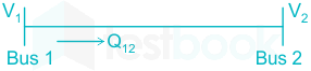
Bus 1 with voltage magnitude V1 = 1.1 pu is sending reactive power Q12 towards bus 2 with voltage magnitude V2 = 1 pu through a lossless transmission line of reactance X. Keeping the voltage at bus 2 fixed at 1 pu, magnitude of voltage at bus 1 is changed, so that the reactive power Q12 sent from bus 1 is increased by 20%. Real power flow through the line under both the conditions is zero. The new value of the voltage magnitude, V1, in pu (rounded off to 2 decimal places), at bus 1 is ________.

58

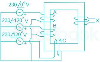
Windings 'A', 'B' and 'C' have 20 turns each and are wound on the same iron core as shown, along with winding 'X' which has 2 turns. The figure shows the sense (clockwise/anti-clockwise) of each of the windings only and does not reflect the exact number of turns. If windings 'A', 'B' and 'C' are supplied with balanced 3-phase voltages at 50 Hz and there is no core saturation, the no-load RMS voltage (in V, rounded off to 2 decimal places) across winding 'X' is

59

A cylindrical rotor synchronous generator has steady state synchronous reactance of 0.7 pu and sub transient reactance of 0.2 pu. It is operating at (1 + j0) pu terminal voltage with an internal emf of (1 + j0.7) pu. Following a three-phase solid short circuit fault at the terminal of the generator, the magnitude of the sub transient internal emf (rounded off to 2 decimal places) is______ pu.

60

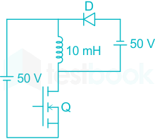
In the dc-dc converter circuit shown, switch Q is switched at a frequency of 10 kHz with a duty ratio of 0.6. All components of the circuit are ideal, and the initial current in the inductor is zero. Energy stored in the inductor in mJ (rounded off to 2 decimal places) at the end of 10 complete switching cycles is ________

61

A single-phase, full-bridge, fully controlled thyristor rectifier feeds a load comprising a 10 Ω resistance in series with a very large inductance. The rectifier is fed from an ideal 230 V, 50 Hz sinusoidal source through cables which have negligible internal resistance and a total inductance of 2.28 mH. If the thyristors are triggered at an angle α = 45°, the commutation overlap angle in degree (rounded off to 2 decimal places) is _______

62

A non-ideal Si-based pn junction diode is tested by sweeping the bias applied across its terminals from -5 V to +5 V. The effective thermal voltage, VT, for the diode is measured to be (29 ± 2) mV. The resolution of the voltage source in the measurement range is 1 mV. The percentage uncertainty (rounded off to 2 decimal places) in the measured current at a bias voltage of 0.02 V is______

63

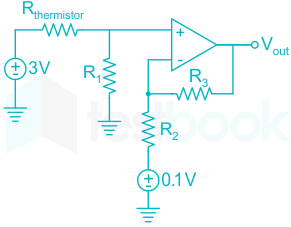
The temperature of the coolant oil bath for a transformer is monitored using the circuit shown. It contains a thermistor with a temperature-dependent resistance, Rthermistor =2 (1 + α T) kΩ, where T is temperature in °C. The temperature coefficient, α, is –(4 ± 0.25) %/°C. Circuit parameters: R1 = 1 kΩ, R2 = 1.3 kΩ, R3 = 2.6 kΩ. The error in the output signal (in V, rounded off to 2 decimal places) at 150°C is _______

64

An 8085 microprocessor accesses two memory locations (2001H) and (2002H), that contain 8-bit numbers 98H and B1H, respectively. The following program is executed:

LXI H, 2001H

MVI A, 21H

INX H

ADD M

INX H

MOV M, A

HLT

At the end of this program, the memory location 2003H contains the number in decimal (base 10) from _______

65

A conducting square loop of side length 1 m is placed at a distance of 1 m from a long straight wire carrying a current l = 2 A as shown below. The mutual inductance, in nH (rounded off to 2 decimal places), between the conducting loop and the long wire is _____,

Attempt this paper under real exam conditions

Timed interface, section switching, instant scoring, and question-by-question analytics — free.

Start Timed Attempt