Official Paper

GATE EE 2019 Official Paper (Previous Year Paper)

65 questions · 180 minutes · with answers · free

General Aptitude (10 questions)

1

I am not sure if the bus that has been booked will be able to _________ all the students.

  1. ((a))

    sit

  2. ((b))

    deteriorate

  3. ((c))

    fill

  4. ((d))

    accommodate

Show Answer
Answer: ((d))

accommodate

Correct answer: Option 4 (accommodate)

The blank requires a word which means 'provide lodging or sufficient space for'.

Accommodate is thus the correct answer. Other words (like 'sit', 'deteriorate' and 'fill') does not fit the context of the sentence.

NOTE: 'Deteriorate' means 'become progressively worse'.

2

The passengers were angry ________ the airline staff about the delay.

  1. ((a))

    on

  2. ((b))

    about

  3. ((c))

    with

  4. ((d))

    towards

Show Answer
Answer: ((c))

with

Correct answer: Option 3 (with)

The correct preposition to be used in the blank is 'with'.

Other prepositions ('on', 'about', and 'towards') do not fit the context.

NOTE: 'On' is basically used as a preposition of position. It is used to show the placement of something.

Example: He placed the lid on the cooker.

'About' is basically used to refer to something that the subject needs to talk about.

Example: Ellie is crazy about this movie.

'Towards' is basically used to refer to a position one is moving towards.

Example: They drove towards the German frontier.

3

The missing number in the given sequence 343, 1331, ________, 4913 is

  1. ((a))

    3375

  2. ((b))

    2744

  3. ((c))

    2197

  4. ((d))

    4096

Show Answer
Answer: ((c))

2197

343 – 73

1331 – 113

4913 – 173

The given series is representing cubes of prime numbers.

The missing prime number is 13.

Now, the missing number is 133 = 2197

4

It takes two hours for a person X to mow the lawn. Y can mow the same lawn in four hours. How long (in minutes) will it take X and Y, if they work together to mow the lawn?

  1. ((a))

    60

  2. ((b))

    80

  3. ((c))

    90

  4. ((d))

    120

Show Answer
Answer: ((b))

80

X takes 2 hours to move a lawn. So, the work done by X in one hour = ½

Y takes 4 hours to move a lawn. So, the work done by Y in one hour = ¼

If both are working together, the work done in one hour =12+14=34= \frac{1}{2} + \frac{1}{4} = \frac{3}{4}

Time taken to complete the work =134=43hours=43×60=80;min= \frac{1}{{\frac{3}{4}}} = \frac{4}{3}hours = \frac{4}{3} \times 60 = 80;min

5

Newspapers are a constant source of delight and recreation for me. The ____ trouble is that I read ____ many of them.

  1. ((a))

    even, quite

  2. ((b))

    even, too

  3. ((c))

    only, quite

  4. ((d))

    only, too

Show Answer
Answer: ((d))

only, too

Let us try to solve this question step-by-step.

The first blank requires an adjective and 'only' seems to be the correct alternative. 'Even' cannot be used with 'trouble'.

So, options 1 and 2 are already rejected.

Option 3 gives 'quite' as the alternative and option 4 gives 'too' as the alternative. The latter is definitely more suitable as 'too' is more definitive.

NOTE: 'quite a lot' is the correct usage.

6

How many integers are there between 100 and 1000 all of whose digits are even?

  1. ((a))

    60

  2. ((b))

    80

  3. ((c))

    100

  4. ((d))

    90

Show Answer
Answer: ((c))

100

We need the numbers between 100 and 1000 and all the digits should be even.

As the required numbers are greater than 100 and less than 1000, all the numbers have 3 digits only.

As we can fill each digit with an even number,

Possible even numbers to fill unit place = 0, 2, 4, 6, 8 (5 possibilities)

Possible even numbers to fill tens place = 0, 2, 4, 6, 8 (5 possibilities)

Possible even numbers to fill hundreds place = 2, 4, 6, 8 (4 possibilities)

Total number of choices =5C1×5C1×4C1=5×5×4=100= {5_{{C_1}}} \times {5_{{C_1}}} \times {4_{{C_1}}} = 5 \times 5 \times 4 = 100

7

The ratio of the number of boys and girls who participated in an examination is 4 : 3. The total percentage of candidates who passed the examination is 80 and the percentage of girls who passed is 90. The percentage of boys who passed is ______.

  1. ((a))

    55.50

  2. ((b))

    72.50

  3. ((c))

    80.50

  4. ((d))

    90.00

Show Answer
Answer: ((b))

72.50

The ratio of the number of boys and girls who participated in an examination is 4 : 3.

Let, the number of boys = 4x

Now, the number of girls = 3x

Total number of the students = 4x + 3x = 7x

The total percentage of candidates who passed the examination = 80%

So, the total number of candidates who passed the examination = 0.8 × 7x = 5.6 x

The percentage of girls who passed the examination = 90%

So, the total number of girls who passed the examination = 0.9 × 3x = 2.7 x

Total number of boys who passes the examination = 5.6x – 2.7x = 2.9x

The percentage of boys who passed the examination 2.9x4x×100=72.5%\frac{{2.9x}}{{4x}} \times 100 = 72.5\%

8

An award-winning study by a group of researchers suggests that men are as prone to buying on impulse as women but women feel more guilty about shopping.

Which one of the following statements can be inferred from the given text?

  1. ((a))

    Some men and women indulge in buying on impulse.

  2. ((b))

    All men and women indulge in buying on impulse.

  3. ((c))

    Few men and women indulge in buying on impulse.

  4. ((d))

    Many men and women indulge in buying on impulse.

Show Answer
Answer: ((a))

Some men and women indulge in buying on impulse.

The given statement provides gives the following information:

I. Men and women are equally prone to buying on impulse.

II. Women feel more guilty about it than men. 

Option 1 is can be logically inferred from the given statement. 

Option 2 cannot be said as we do not have enough information. Hence it is logically unnecessary.

Option 3 and 4 cannot be said as we do not have enough information to count the number of men and women buying on impulse as 'few' or 'many'. Hence it is logically unnecessary.

9

Given two sets X = {1, 2, 3} and Y = {2, 3, 4}, we construct a set Z of all possible fractions where the numerators belong to set X and the denominators belong to set Y. The product of elements having minimum and maximum values in the set Z is ____.

  1. ((a))

    1/12

  2. ((b))

    1/8

  3. ((c))

    1/6

  4. ((d))

    3/8

Show Answer
Answer: ((d))

3/8

X = {1, 2, 3}, Y = {2, 3, 4}

Z consists of all possible fractions where the numerators belong to set X and the denominators belong to set Y.

\(Z = \left{ {\frac{1}{2},\frac{1}{3},\frac{1}{4},\frac{2}{2},\frac{2}{3},\frac{2}{4},\frac{3}{2},\frac{3}{3},\frac{3}{4}} \right}\)

\(Z = \left{ {\frac{1}{2},\frac{1}{3},\frac{1}{4},1,\frac{2}{3},\frac{3}{2},\frac{3}{4}} \right}\)

Minimum value in the set Z = 1/4

Maximum value in the set Z = 3/2

The product of minimum and maximum values in the set Z=14×32=38Z = \frac{1}{4} \times \frac{3}{2} = \frac{3}{8}

10

Consider five people – Mita, Ganga, Rekha, Lakshmi and Sana. Ganga is taller than both Rekha and Lakshmi. Lakshmi is taller than Sana. Mita is taller than Ganga. Which of the following conclusions are true?

  1. Lakshmi is taller than Rekha
  2. Rekha is shorter than Mita
  3. Rekha is taller than Sana
  4. Sana is shorter than Ganga
  1. ((a))

    1 and 3

  2. ((b))

    3 only

  3. ((c))

    2 and 4

  4. ((d))

    1 only

Show Answer
Answer: ((c))

2 and 4

Ganga (G) is taller than both Rekha (R) and Lakshmi (L)

⇒ G > R, G > L

Lakshmi (L) is taller than Sana (S)

⇒ L > S

Now, it becomes G > R, G > L > S

Mita (M) is taller than Ganga (G)

⇒ M > G

Now, it becomes M > G > R, M > G > L > S

Conclusion 1: Lakshmi is taller than Rekha (L > R)

As there is no clear relation between Lakshmi and Rekha, the given conclusion may or may not be true.

Conclusion 2: Rekha is shorter than Mita (R < M)

From the relation M > G > R, it is clearly true.

Conclusion 3: Rekha is taller than Sana (R > S)

As there is no clear relation between Rekha and Sana, the given conclusion may or may not be true.

Conclusion 4: Sana is shorter than Ganga (S < G)

From the relation M > G > L > S, it is clearly true.

Hence, conclusion 2 and 4 are true.

Electrical Engineering (55 questions)

11

The inverse Laplace transform of H(s)=s+3s2+2s+1H\left( s \right) = \frac{{s + 3}}{{{s^2} + 2s + 1}} for t ≥ 0 is

  1. ((a))

    3te-t + e-t

  2. ((b))

    3e-t

  3. ((c))

    2te-t + e-t

  4. ((d))

    4te-t + e-t

Show Answer
Answer: ((c))

2te-t + e-t

Concept:

Some pairs of Laplace transforms are given below.

eat1s+a{e^{ - at}} \leftrightarrow \frac{1}{{s + a}}

tneatn!(s+a)n+1{t^n}{e^{ - at}} \leftrightarrow \frac{{n!}}{{{{\left( {s + a} \right)}^{n + 1}}}}

Calculation:

Given:

H(s)=s+3s2+2s+1H\left( s \right) = \frac{{s + 3}}{{{s^2} + 2s + 1}}

s+3(s+1)2=s+1(s+1)2+2(s+1)2\Rightarrow \frac{{s + 3}}{{{{\left( {s + 1} \right)}^2}}}= \frac{{s + 1}}{{{{\left( {s + 1} \right)}^2}}} + \frac{2}{{{{\left( {s + 1} \right)}^2}}}

1(s+1)+2(s+1)2\Rightarrow \frac{1}{{\left( {s + 1} \right)}} + \frac{2}{{{{\left( {s + 1} \right)}^2}}}

By applying inverse Laplace transform

⇒ H(t) = e-t + 2t e-t

12

M is a 2 × 2 matrix with eigenvalues 4 and 9. The eigenvalues of M2 are

  1. ((a))

    4 and 9

  2. ((b))

    2 and 3

  3. ((c))

    -2 and -3

  4. ((d))

    16 and 81

Show Answer
Answer: ((d))

16 and 81

Concept:

If A is any square matrix of order n, we can form the matrix [A – λI], where I is the nth order unit matrix. The determinant of this matrix equated to zero i.e. |A – λI| = 0 is called the characteristic equation of A.

The roots of the characteristic equation are called Eigen values or latent roots or characteristic roots of matrix A.

Properties of Eigen values:

  • The sum of Eigen values of a matrix A is equal to the trace of that matrix A
  • The product of Eigen values of a matrix A is equal to the determinant of that matrix A
  • If λ is an eigen value of a matrix A, then λn will be an eigen value of a matrix An.
  • If λ is an eigen value of a matrix A, then kλ will be an eigen value of a matrix kA where k is a scalar


Calculation:

If λ is an Eigen value of a matrix M, then λ2 will be an Eigen value of the matrix M2

Given that, Eigen values of M are 4, 9.

Eigen values of M2 = 42, 92 = 16, 81

13

The partial differential equation 2ut2c2(2ux2+2uy2)=0\frac{{{\partial ^2}u}}{{\partial {t^2}}} - {c^2}\left( {\frac{{{\partial ^2}u}}{{\partial {x^2}}} + \frac{{{\partial ^2}u}}{{\partial {y^2}}}} \right) = 0; where c ≠ 0 is known as

  1. ((a))

    Heat equation

  2. ((b))

    Wave equation

  3. ((c))

    Poisson’s equation

  4. ((d))

    Laplace equation

Show Answer
Answer: ((b))

Wave equation

Explanation:

3-D heat equation is given as below

(2Tdx2+2Ty2+2Tz2)+Q(x,t)K=1αTt\left( {\frac{{{\partial ^2}T}}{{d{x^2}}} + \frac{{{\partial ^2}T}}{{\partial {y^2}}} + \frac{{{\partial ^2}T}}{{\partial {z^2}}}} \right) + \frac{{Q\left( {x,t} \right)}}{K} = \frac{1}{\alpha }\frac{{\partial T}}{{\partial t}}

For 1 – D & without heat generation:

2Tx2=1αTt\frac{{{\partial ^2}T}}{{\partial {x^2}}} = \frac{1}{\alpha }\frac{{\partial T}}{{\partial t}}

Where α ÷ thermal diffusivity.

Wave equation is given by:

2ut2=c2(2ux2+2uy2)\frac{{{\partial ^2}u}}{{\partial {t^2}}} = {c^2}\left( {\frac{{{\partial ^2}u}}{{\partial {x^2}}} + \frac{{{\partial ^2}u}}{{\partial {y^2}}}} \right)      (2-D)

Laplace equation:

2ux2+2uy2+2uz2=0\frac{{{\partial ^2}u}}{{\partial {x^2}}} + \frac{{{\partial ^2}u}}{{\partial {y^2}}} + \frac{{{\partial ^2}u}}{{\partial {z^2}}} = 0     (3-D)

2u=0{\nabla ^2}u = 0

Poisson’s equation: 

2V=ρvϵ{\nabla ^2}V = - \frac{{{\rho _v}}}{\epsilon}

14

Which one of the following functions is analytic in the region |z| ≤ 1?

  1. ((a))

    z21z\frac{{{z^2} - 1}}{z}

  2. ((b))

    z21z+2\frac{{{z^2} - 1}}{{z + 2}}

  3. ((c))

    z21z0.5\frac{{{z^2} - 1}}{{z - 0.5}}

  4. ((d))

    z21z+j0.5\frac{{{z^2} - 1}}{{z + j0.5}}

Show Answer
Answer: ((b))

z21z+2\frac{{{z^2} - 1}}{{z + 2}}

Given region |z|≤ 1

a) z21z\frac{{{z^2} - 1}}{z}

z = 0 |z| = 0 ≤ 1

The pole is lies inside the given region.

Hence, the function is not analytic.

b)z21z+2\frac{{{z^2} - 1}}{{z + 2}}

z + 2 = 0 → z = -2 |z| = 2 ≥ 1

the pole is lies outside the given region.

Hence, the function is analytic.

c) z21z0.5\frac{{{z^2} - 1}}{{z - 0.5}}

z – 0.5 = 0 z = 0.5 |z| = 0.5 ≤ 1

The pole is lies inside the given region.

Hence, the function is not analytic.

d) z21z+j0.5\frac{{{z^2} - 1}}{{z + j0.5}}

z + j 0.5 = 0 ⇒ z = -j 0.5 ⇒ |z| = 0.5 ≤ 1

The pole is lies inside the given region.

Hence, the function is not analytic.

15

The mean-square of a zero-mean random process is kTC\frac{{kT}}{C}, where k is Boltzmann’s constant, T is the absolute temperature, and C is a capacitance. The standard deviation of the random process is

  1. ((a))

    kTC\frac{{kT}}{C}

  2. ((b))

    kTC\sqrt {\frac{{kT}}{C}}

  3. ((c))

    CkT\frac{C}{{kT}}

  4. ((d))

    kTC\frac{{\sqrt {kT} }}{C}

Show Answer
Answer: ((b))

kTC\sqrt {\frac{{kT}}{C}}

Concept:

Random variables:

Random variable assigns a real number to each possible outcome.

Let X be a discreet random variable, then

Expectation E(x) = Σxp(x)

The variance of X = R =E[X2]- (E[X])2 

E(x2) = Var(x) + {E(x)}2

Standard;Deviation;σ=VarianceStandard;Deviation;σ=\sqrt{Variance}

Calculation:

Given that, mean = 0

⇒ E[x] = 0

Mean – square = kTC\frac{{kT}}{C}

;E[X2]=kTC\Rightarrow ;E\left[ {{X^2}} \right] = \frac{{kT}}{C}

We know that,

Variance =E[X2][E[X]]2= E\left[ {{X^2}} \right] - {\left[ {E\left[ X \right]} \right]^2}

V=kTCV = \frac{{kT}}{C}

⇒ Standard deviation =variance=kTC= \sqrt {variance} = \sqrt {\frac{{kT}}{C}}

16

A system transfer function is H(s)=a1s2+b1s+c1a2s2+b2s+c2H\left( s \right) = \frac{{{a_1}{s^2} + {b_1}s + {c_1}}}{{{a_2}{s^2} + {b_2}s + {c_2}}}. If a1 = b1 = 0, and all other coefficients are positive, the transfer function represents a

  1. ((a))

    low pass filter

  2. ((b))

    high pass filter

  3. ((c))

    band pass filter

  4. ((d))

    notch filter

Show Answer
Answer: ((a))

low pass filter

H(s)=a1s2+b1s+c1a2s2+b2s+c2H\left( s \right) = \frac{{{a_1}{s^2} + {b_1}s + {c_1}}}{{{a_2}{s^2} + {b_2}s + {c_2}}}

a1 = b1 = 0 

H(s)=c1a2s2+b2s+c2\Rightarrow H\left( s \right) = \frac{{{c_1}}}{{{a_2}{s^2} + {b_2}s + {c_2}}}

at s = 0, H(0) = c1c2\frac{{{c_1}}}{{{c_2}}}

at s = ∞, H (∞) = 0

The given function passes the signal at low frequencies only.

Hence the given transfer function represents low pass filter.

17

The symbols, a and T, represent positive quantities, and u(t) is the unit step function. Which one of the following impulse responses is NOT the output of a causal linear time-invariant system?

  1. ((a))

    e+at u(t)

  2. ((b))

    e-a(t + T) u(t)

  3. ((c))

    1 + e-at u(t)

  4. ((d))

    e-a(t - T) u(t)

Show Answer
Answer: ((c))

1 + e-at u(t)

Concept:

Linear system

The system is said to be linear if it follows Homogenous and Superposition property.

  1. The system is homogenous if 

y(t) = α1x(t) 

y(t) = α2x(t)

  1. The system follows Superposition if

y(t) = α1x(t) + α2x(t)

Time invariant system

if y(t - t0) = x(t - t0)

and y(t') = x(t - t0)  

Causal system

A system is said to be causal systems if its output depends on present and past inputs only and not on future inputs

For a causal system, impulse response must be zero for t < 0 i.e., h(t) = 0 for t < 0

Analysis:

(1) eat u(t) - causal system, Linear, Time-invariant

(2) e-a(t + T)u(t) - casual system, linear, Time invariant

(3) 1 + e-at u(t) - Non causal system, Non-linear, Time-invariant [ Due to constant term 1, h(t) exist also for t < 0. So, the system is Non - Causal ] 

(4) e-a(t - T)u(t) - casual system, linear, Time invariant

Hence option (3) is correct

18

A 5 kVA, 50 V/100 V, single-phase transformer has a secondary terminal voltage of 95 V when loaded. The regulation of the transformer is

  1. ((a))

    4.5%

  2. ((b))

    9%

  3. ((c))

    5%

  4. ((d))

    1%

Show Answer
Answer: ((c))

5%

Concept:

Voltage regulation:

Voltage regulation is the change in secondary terminal voltage from no load to full load at a specific power factor of load and the change is expressed in percentage.

E2 = no-load secondary voltage

V2 = full load secondary voltage

Voltage regulation for the transformer is given by the ratio of change in secondary terminal voltage from no load to full load to no load secondary voltage.

Voltage regulation =E2V2E2= \frac{{{E_2} - {V_2}}}{{{E_2}}}

It can also be expressed as,

Regulation \(= \frac{{{I_2}{R_{02}}\cos {\phi 2} \pm {I_2}{X{02}}\sin {\phi _2}}}{{{E_2}}}\)

  • sign is used for lagging loads and

-  sign is used for leading loads

Explanation:

% voltage regulation =No;load;voltagefull;load;voltage;No;load;voltage;×100= \frac{{No;load;voltage - full;load;voltage;}}{{No;load;voltage;}} \times 100

Given that, no load voltage = 100 V

full load voltage = 95 V

%V.R.=10095100×100=5%\% V.R. = \frac{{100 - 95}}{{100}} \times 100 = 5\%

19

A six-pulse thyristor bridge rectifier is connected to a balanced three-phase, 50 Hz AC source. Assuming that the DC output current of the rectifier is constant, the lowest harmonic component in the AC input current is

  1. ((a))

    100 Hz

  2. ((b))

    150 Hz

  3. ((c))

    250 Hz

  4. ((d))

    300 Hz

Show Answer
Answer: ((c))

250 Hz

In a six-pulse thyristor bridge rectifier, the harmonics present are = 6 k ± 1

So, the harmonics are = 5, 7, 11, 13, ...

lowest harmonic component = 5th harmonic supply frequency = 50 Hz

5th harmonic frequency = 5f = 250 Hz

20

The parameter of an equivalent circuit of a three-phase induction motor affected by reducing the rms value of the supply voltage at the rated frequency is

  1. ((a))

    rotor resistance

  2. ((b))

    rotor leakage reactance

  3. ((c))

    magnetizing reactance

  4. ((d))

    stator resistance

Show Answer
Answer: ((c))

magnetizing reactance

Magnetic reactance (Xm) is depends on airgap flux and the flux is depends on V/f.

Xm ∝ ϕ ∝ V/f

Hence, magnetizing reactance gets affected by reducing the rms value of the supply at the rated frequency.

Additional Information

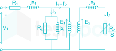
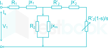
The total resistance at rotor is represented as r2s\frac{{{r_2}}}{s}, where ss is slip. Now, if we create an equivalent transformer circuit for induction motor, the secondary resistance will be r2{r_2}. Thus the load resistance will be r2(1s1){r_2}\left( {\frac{1}{s} - 1} \right).

Induction motor modelled as a transformer

When all the rotor parameters are shifted to stator side induction motor circuit is given by

So, r2(1s1)r_{2}^{'}\left( \frac{1}{s}-1 \right) is the resistance which shows the power which is converted to mechanical power output or useful power.

21

A three-phase synchronous motor draws 200 A from the line at unity power factor at rated load. Considering the same line voltage and load, the line current at a power factor of 0.5 leading is

  1. ((a))

    100 A

  2. ((b))

    200 A

  3. ((c))

    300 A

  4. ((d))

    400 A

Show Answer
Answer: ((d))

400 A

Given the, Line current (IL1) = 200 A

Power factor (cos ϕ1) = 1

Power (P1)=3VL1IL1cosϕ1\left( {{P_1}} \right) = \sqrt 3 {V_{L1}}{I_{{L_1}}}cos{\phi _1}

When the power factor changes to 0.5 leading. The power drawn will be same.

And given that line voltage is same

VL2 = VL1

cos ϕ2 = 0.5

P2=3VL2IL2cosϕ2{P_2} = \sqrt 3 {V_{L2}}{I_{L2}}cos{\phi _2} 

⇒ P1 = P2

\(\Rightarrow \sqrt 3 {V_{L1}}{I_{L1}}\cos {\phi 1} = \sqrt 3 {V{L2}}{I_{L2}}\cos {\phi _2}\)

3VL1×200×1=3×VL2×IL2×0.5\Rightarrow \sqrt 3 {V_{L1}} \times 200 \times 1 = \sqrt 3 \times {V_{L2}} \times {I_{L2}} \times 0.5

⇒ IL2 = 400 A

22

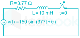
In the circuit shown below, the switch is closed at t = 0. The value of θ in degrees which will give the maximum value of DC offset of the current at the time of switching is

  1. ((a))

    60

  2. ((b))

    -45

  3. ((c))

    90

  4. ((d))

    -30

Show Answer
Answer: ((b))

-45

The solution for i(t) is

i(t)=Vmzsin(ωt+θϕ)Vmzsin(θϕ)etτi\left( t \right) = \frac{{{V_m}}}{{\left| z \right|}}\sin \left( {\omega t + \theta - \phi } \right) - \frac{{{V_m}}}{{\left| z \right|}}\sin \left( {\theta - \phi } \right){e^{ - \frac{t}{\tau }}}

DC offset value =Vmzsin(θϕ)etτ= - \frac{{{V_m}}}{{\left| z \right|}}\sin \left( {\theta - \phi } \right){e^{ - \frac{t}{\tau }}}

Maximum value of DC offset value occurs at

  • sin (θ - ϕ) = -1

⇒ θ - ϕ = -90°

⇒ θ = ϕ – 90°

ϕ=tan1(ωLR)=tan1(377×10×1033.77)=45;\phi = {\tan ^{ - 1}}\left( {\frac{{\omega L}}{R}} \right) = {\tan ^{ - 1}}\left( {\frac{{377 \times 10 \times {{10}^{ - 3}}}}{{3.77}}} \right) = 45^\circ ;

⇒ θ = 45° - 90° = -45°

23

The output response of a system is denoted as y(t), and its Laplace transform is given by Y(s)=10s(s2+s+1002)Y\left( s \right) = \frac{{10}}{{s\left( {{s^2} + s + 100\sqrt 2 } \right)}}. The steady state value of y(t) is

  1. ((a))

    1102\frac{1}{{10\sqrt 2 }}

  2. ((b))

    10√2

  3. ((c))

    11002\frac{1}{{100\sqrt 2 }}

  4. ((d))

    100√2

Show Answer
Answer: ((a))

1102\frac{1}{{10\sqrt 2 }}

Concept:

The final value theorem is given as:

\(f\left( t \right){\left. \right|{t = \infty }} = \mathop {\lim }\limits{s \to 0} \left[ {sF\left( s \right)} \right]\)

This theorem is only applicable when:

(I) f(t) = 0; t < 0

(II) The term [sF(s)] should have poles in the left-hand side of the s-plane.

Explanation:   

Y(s)=10s(s2+s+1002)Y\left( s \right) = \frac{{10}}{{s\left( {{s^2} + s + 100\sqrt 2 } \right)}}

By using Final value theorem, the steady state value of the given system is

=lts0s10s(s2+s+1002)= \mathop {{\rm{lt}}}\limits_{s \to 0} s\frac{{10}}{{s\left( {{s^2} + s + 100\sqrt 2 } \right)}}

=101002=1102= \frac{{10}}{{100\sqrt 2 }} = \frac{1}{{10\sqrt 2 }}

24

The open loop transfer function of a unity feedback system is given by G(s)=πe0.25ssG\left( s \right) = \frac{{\pi {e^{ - 0.25s}}}}{s}. In G(s) plane, the Nyquist plot of G(s) passes through the negative real axis at the point

  1. ((a))

    (−0.5, j0)

  2. ((b))

    (−0.75, j0)

  3. ((c))

    (−1.25, j0)

  4. ((d))

    (−1.5, j0)

Show Answer
Answer: ((a))

(−0.5, j0)

G(s)=πe0.25ssG\left( s \right) = \frac{{\pi {e^{ - 0.25s}}}}{s}

In G(s) plane, the Nyquist plot of G(S) passes through the negative real axis at the point (-a, j0)

a = magnitude of G(s) at ω = ωpc

ωpc is phase cross over frequency.

at ω=ωpc,G(jω)=180{\rm{\omega}} = {{\rm{\omega }}_{{\rm{pc}}}},\angle G\left( {j\omega } \right) = - 180^\circ

⇒ -0.25 ωpc – 90 = -180

⇒ ωpc = 2π

\({\left| {G\left( {j\omega } \right)} \right|{{\rm{\omega }} = {{\rm{\omega }}{{\rm{pc}}}}}} = \frac{{\pi \left( 1 \right)}}{{2\pi }} = 0.5\)

(-a, j0) = (0.5, j0)

25

The characteristic equation of a linear time-invariant (LTI) system is given by Δ(s) = s4 + 3s3 + 3s2 + s + k = 0. The system is BIBO stable if

  1. ((a))

    0<k<1290 < k < \frac{{12}}{9}

  2. ((b))

    k > 3

  3. ((c))

    0<k<890 < k < \frac{8}{9}

  4. ((d))

    k > 6

Show Answer
Answer: ((c))

0<k<890 < k < \frac{8}{9}

Δ(s)=s4+3s3+3s2+s+k=0{\rm{\Delta }}\left( s \right) = {s^4} + 3{s^3} + 3{s^2} + s + k = 0

\(\left. {\begin{array}{{20}{c}} {{s^4}}\ {{s^3}}\ {\begin{array}{{20}{c}} {{s^2}}\ {\begin{array}{{20}{c}} {{s^1}}\ {{s^0}} \end{array}} \end{array}} \end{array}} \right|\begin{array}{{20}{c}} 1&3&k\ 3&1&0\ {8/3}&k&{}\ {\left( {\frac{{8/3 - 3k}}{{8/3}}} \right)}&0&{}\ k&0&{} \end{array}\)

The system to be stable,

k > 0 and (833k)>0\left( {\frac{8}{3} - 3k} \right) > 0

3k<83k<89\Rightarrow 3k < \frac{8}{3} \Rightarrow k < \frac{8}{9}

0<k<89\Rightarrow 0 < k < \frac{8}{9}

26

Given, Vgs is the gate-source voltage, Vds is the drain source voltage, and Vth is the threshold voltage of an enhancement type NMOS transistor, the conditions for transistor to be biased in saturation are

  1. ((a))

    Vgs < Vth; Vds ≥ Vgs - Vth

  2. ((b))

    Vgs > Vth; Vds ≥ Vgs – Vth

  3. ((c))

    Vgs > Vth; Vds ≤ Vgs – Vth

  4. ((d))

    Vgs < Vth; Vds ≤ Vgs – Vth

Show Answer
Answer: ((b))

Vgs > Vth; Vds ≥ Vgs – Vth

At Vgs = 0, no current flows through the MOS transistors channel because the field effect around the gate is insufficient to create or open the n-type channel. Then the transistor is in its cut-off region acting as an open switch.

As we now gradually increase the positive gate-source voltage Vgs, the field effect begins to enhance the channel regions conductivity and there becomes a point where the channel starts to conduct. This point is known as the threshold voltage Vth. As we increase Vgs more positive, the conductive channel becomes wider (less resistance) with the amount of drain current (Id).

Therefore, the n-channel enhancement MOSFET will be in its cut-off mode when the gate-source voltage (VGS) is less than its threshold voltage level (Vth) and its channel conducts or saturates when Vgs is above this threshold level.

27

A current controlled current source (CCCS) has an input impedance of 10 Ω and output impedance of 100 kΩ. When this CCCS is used in a negative feedback closed loop with a loop gain of 9, the closed loop output impedance is

  1. ((a))

    10 Ω

  2. ((b))

    100 Ω

  3. ((c))

    100 kΩ

  4. ((d))

    1000 kΩ

Show Answer
Answer: ((d))

1000 kΩ

Concept:

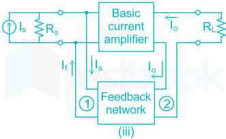
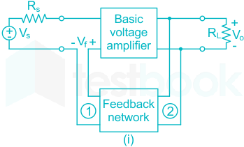
A current controlled current source (CCCS) is as shown:


This is also called as a Current-Shunt feedback with a current amplifier:

Input Resistance:

Rif=Ri1+Aβ{R_{if}} = \frac{{{R_i}}}{{1 + A\beta }}  (Decreases)

Output Resistance:

Rof=Ro(1+Aβ){R_{of}} = {R_o}\left( {1 + A\beta } \right) (Increases)

Calculation:

Input impedance = 10 Ω

Output impedance = 100 kΩ

loop again (Aβ) = 9

Closed loop impedance will be:

Zout = Zo [1 + Aβ]

= 100 × 103 [1 + 9]

= 1000 kΩ

Calculation:

Given that,

Input impedance = 10 Ω

Output impedance = 100 kΩ

loop again (Aβ) = 9

closed loop impedance = Zo [1 + Aβ]

= 100 × 103 [1 + 9]

= 1000 kΩ

Important Points


i) Voltage-Series feedback with voltage amplifier:

Input Resistance:

Rif=Ri(1+Aβ){R_{if}} = {R_i}\left( {1 + A\beta } \right) (Increases)

Output Resistance:

Rof=Ro1+Aβ{R_{of}} = \frac{{{R_o}}}{{1 + A\beta }} (Decreases)

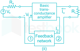
ii) Current-Series feedback with a transconductance amplifier:

Input Resistance:

Rif=Ri(1+Aβ){R_{if}} = {R_i}\left( {1 + A\beta } \right)  (Increases)

Output Resistance:

R0f=R0(1+Aβ){R_{0f}} = {R_0}\left( {1 + A\beta } \right) (Increases)

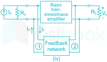
iv) Voltage-Shunt feedback with trans resistance amplifier:

Input Resistance:

Rif=Ri1+Aβ{R_{if}} = \frac{{{R_i}}}{{1 + A\beta }} (Decreases)

Output Resistance:

Rof=Ro1+Aβ{R_{of}} = \frac{{{R_o}}}{{1 + A\beta }} (Decreases)

28

If f = 2x3 + 3y2 + 4z, the value of line integral \(\mathop \smallint \limits_C {\rm{gradf}}.{\rm{dr}}\) evaluated over contour C formed by the segments (-3, -3, 2) → (2, -3, 2) → (2, 6, 2) → (2, 6, -1) is ________.

29

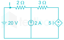
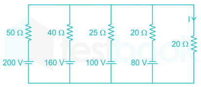
The current I flowing in the circuit shown below in amperes (round off to one decimal place) is ________.

30

A co-axial cylindrical capacitor shown in Figure (i) has dielectric with relative permittivity εr1 = 2. When one-fourth portion of the dielectric is replaced with another dielectric of relative permittivity εr2, as shown in Figure (ii), the capacitance is doubled. The value of εr2 is ______.

31

The Ybus matrix of a two-bus power system having two identical parallel lines connected

between them in pu is given as \({Y_{bus}} = \left[ {\begin{array}{*{20}{c}} { - j8}&{j20}\ {j20}&{ - j8} \end{array}} \right]\).

The magnitude of the series reactance of each line in pu (round off up to one decimal place) is ____________.

32

Five alternators each rated 5 MVA, 13.2 kV with 25% of reactance on its own base are connected in parallel to a busbar. The short-circuit level in MVA at the busbar is_________.

33

The total impedance of the secondary winding, leads, and burden of a 5 A CT is 0.01 Ω. If the fault current is 20 times the rated primary current of the CT, the VA output of the CT is ________.

34

The rank of the matrix, \(M = \left[ {\begin{array}{*{20}{c}} 0&1&1\ 1&0&1\ 1&1&0 \end{array}} \right]\), is _________.

35

The output voltage of a single-phase full bridge voltage source inverter is controlled by unipolar PWM with one pulse per half cycle. For the fundamental rms component of output voltage to be 75% of DC voltage, the required pulse width in degrees (round off up to one decimal place) is __________.

36

Consider a 2 × 2 matrix \(M = \left[ {\begin{array}{{20}{c}} {{v_1}}&{{v_2}} \end{array}} \right]\), where, v1 and v2 are the column vectors. Suppose \({M^{ - 1}} = \left[ {\begin{array}{{20}{c}} {u_1^T}\ {u_2^T} \end{array}} \right]\), where uT1 and uT2 are the row vectors. Consider the following statements.

Statement: uT1v1 = 1 and uT2v2 = 1

Statement: uT1v2 = 0 and uT2v1 = 0

Which of the following options is correct?

  1. ((a))

    Statement 1 is true and statement 2 is false

  2. ((b))

    Statement 2 is true and statement 1 is false

  3. ((c))

    Both the statements are true

  4. ((d))

    Both the statements are false

Show Answer
Answer: ((c))

Both the statements are true

Let matrix \(M = \left[ {\begin{array}{*{20}{c}} a&b\ c&d \end{array}} \right]\)

\({v_1} = \left[ {\begin{array}{{20}{c}} a\ c \end{array}} \right],;{v_2} = \left[ {\begin{array}{{20}{c}} b\ d \end{array}} \right]\)

\({M^{ - 1}} = \frac{1}{{ad - bc}}\left[ {\begin{array}{*{20}{c}} d&{ - b}\ { - c}&a \end{array}} \right]\)

\(u_1^T = \frac{1}{{ad - bc}}\left[ {\begin{array}{*{20}{c}} d&{ - b} \end{array}} \right]\)

\(u_2^T = \frac{1}{{ad - bc}}\left[ {\begin{array}{*{20}{c}} { - c}&a \end{array}} \right]\)

\(u_1^T{v_1} = \frac{1}{{ad - bc}}\left[ {\begin{array}{{20}{c}} d&{ - b} \end{array}} \right]\left[ {\begin{array}{{20}{c}} a\ c \end{array}} \right] = 1\)

\(u_2^T{v_2} = \frac{1}{{ad - bc}}\left[ {\begin{array}{{20}{c}} { - c}&a \end{array}} \right]\left[ {\begin{array}{{20}{c}} b\ d \end{array}} \right] = 1\)

\(u_1^T{v_2} = \frac{1}{{ad - bc}}\left[ {\begin{array}{{20}{c}} d&{ - b} \end{array}} \right]\left[ {\begin{array}{{20}{c}} b\ d \end{array}} \right] = 0\)

\(u_2^T{v_1} = \frac{1}{{ad - bc}}\left[ {\begin{array}{{20}{c}} { - c}&a \end{array}} \right]\left[ {\begin{array}{{20}{c}} a\ c \end{array}} \right] = 0\)

Both the given statements are true.

37

The closed loop line integral z=5;z3+z2+8z+2dz\mathop \oint \limits_{\left| z \right| = 5}^; \frac{{{z^3} + {z^2} + 8}}{{z + 2}}dz evaluated counter-clockwise, is

  1. ((a))

    +8jπ

  2. ((b))

    -8jπ

  3. ((c))

    -4jπ

  4. ((d))

    +4jπ

Show Answer
Answer: ((a))

+8jπ

Concept:

Residue Theorem: 

If f(z) is analytic in a closed curve C except at a finite number of singular points within C, then

∫cf(z) dz = 2πj × [sum of residues at the singular points within C]

Formula to find residue:

  1. If f(z) has a simple pole at z = a, then

Res;f(a)=limza[(za)f(z)]Res;f\left( a \right) = \mathop {\lim }\limits_{z \to a} \left[ {\left( {z - a} \right)f\left( z \right)} \right]

  1. If f(z) has a pole of order n at z = a, then

\(Res;f\left( a \right) = \frac{1}{{\left( {n - 1} \right)!}}{\left{ {\frac{{{d^{n - 1}}}}{{d{z^{n - 1}}}}\left[ {{{\left( {z - a} \right)}^n}f\left( z \right)} \right]} \right}_{z = a}}\)

Calculation:

\(\mathop \smallint \limits_{\left| z \right| = 5} \frac{{{z^3} + {z^2} + 8}}{{z + 2}}dz\)

z + 2 = 0 z = -2 |z| = 2 < 5

f(x) is not analytic at z = -2

By Cauchy’s residue theorem

Cf(x);dz=2πi×(sum;of;residues)\mathop \oint \limits_C f\left( x \right);dz = 2\pi i \times \left( {sum;of;residues} \right)

At z = -2

Residue of f(x)=ltz2(z+2);z3+z2+8(z+2);dzf\left( x \right) = \mathop {{\rm{lt}}}\limits_{z \to - 2} \left( {z + 2} \right);\frac{{{z^3} + {z^2} + 8}}{{\left( {z + 2} \right)}};dz

= -8 + 4 + 8 = 4

\(\mathop \smallint \limits_{\left| z \right| = 5} \frac{{{z^3} + {z^2} + 8}}{{z + 2}} = 2\pi i\left( 4 \right) = 8\pi i\)


Additional Information

Cauchy’s Theorem:

If f(z) is an analytic function and f’(z) is continuous at each point within and on a closed curve C, then

Cf(z)dz=0\mathop \oint \limits_C f\left( z \right)dz = 0

Cauchy’s Integral Formula:

If f(z) is an analytic function within a closed curve and if a is any point within C, then

f(a)=12πiCf(z)zadzf\left( a \right) = \frac{1}{{2\pi i}}\mathop \oint \limits_C \frac{{f\left( z \right)}}{{z - a}}dz

fn(a)=n!2πiCf(z)(za)n+1dz{f^n}\left( a \right) = \frac{{n!}}{{2\pi i}}\mathop \oint \limits_C \frac{{f\left( z \right)}}{{{{\left( {z - a} \right)}^{n + 1}}}}dz

38

A periodic function f(t), with a period of 2π, is represented as its Fourier series,

\(f\left( t \right) = {a_0} + {\rm{\Sigma }}{n = 1}^\infty ;{a_n}\cos nt + {\rm{\Sigma }}{n = 1}^\infty ;{b_n}\sin nt\)

If

\(f\left( t \right) = { \begin{array}{*{20}{c}} {A\sin t,}&{0 \le t \le \pi }\ {0,}&{\pi < t < 2\pi } \end{array}\) ,

the Fourier series coefficients a1 and b1 of f(t) are

  1. ((a))

    a1=Aπ;b1=0{a_1} = \frac{A}{\pi };{b_1} = 0

  2. ((b))

    a1=A2;b1=0{a_1} = \frac{A}{2};{b_1} = 0

  3. ((c))

    a1=0;b1=A/π{a_1} = 0;{b_1} = A/\pi

  4. ((d))

    a1=0;b1=A2{a_1} = 0;{b_1} = \frac{A}{2}

Show Answer
Answer: ((d))

a1=0;b1=A2{a_1} = 0;{b_1} = \frac{A}{2}

Concept

Any periodic function f(t) of period T = 2π2\pi has a Fourier series given by,

\(f\left( t \right) = {a_0} + {\rm{\Sigma }}{n = 1}^\infty ;{a_n}\cos nt + {\rm{\Sigma }}{n = 1}^\infty ;{b_n}\sin nt\)

where an , bn & ao are called coefficients

\({a_n} = \frac{2}{T}\mathop \smallint \limits_0^T f\left( t \right)\cos n{\omega _o}t;dt\) ,  \({b_n} = \frac{2}{T}\mathop \smallint \limits_0^T f\left( t \right)\sin n\omega t;dt\)

Explanation: 

\(f\left( t \right) = \left{ {\begin{array}{*{20}{c}} {A\sin t,}&{0 \le t \le \pi }\ {0,}&{\pi < t < 2\pi } \end{array}} \right.\)

\({a_n} = \frac{2}{T}\mathop \smallint \limits_0^T f\left( t \right)\cos n{\omega _o}t;dt\)

\({a_1} = \frac{2}{T}\mathop \smallint \limits_0^T f\left( t \right){\rm{cost}}dt\)

\(= \frac{1}{\pi }\mathop \smallint \limits_0^T A\sin t\cos tdt\)

\(= \frac{A}{{2\pi }}\mathop \smallint \limits_0^T \sin 2t;dt = \frac{A}{{2\pi }}\mathop \smallint \limits_0^T \sin 2t;dt\)

=A2π[cos2t2]0π=0= \frac{A}{{2\pi }}\left[ { - \frac{{\cos 2t}}{2}} \right]_0^\pi = 0

\({b_n} = \frac{2}{T}\mathop \smallint \limits_0^T f\left( t \right)\sin n\omega t;dt\)

\({b_1} = \frac{2}{{2\pi }}\mathop \smallint \limits_0^{2\pi } f\left( t \right)\sin tdt\)

\(= \frac{1}{\pi }\mathop \smallint \limits_0^\pi A\sin t\sin t;dt\)

\(= \frac{A}{\pi }\mathop \smallint \limits_0^\pi {\sin ^2}tdt\)

\(= \frac{A}{\pi }\mathop \smallint \limits_0^\pi A{\sin ^2}t;dt\)

\(= ;\frac{A}{\pi }\mathop \smallint \limits_0^\pi \frac{{1 - \cos 2t}}{2};dt\)

\(= \frac{A}{{2\pi }}\mathop \smallint \limits_0^\pi \left[ {t - \frac{{sin2t}}{2}} \right]_0^\pi\)

=A2π[(π0)(00)]=A2 = \frac{A}{{2\pi }}\left[ {\left( {\pi - 0} \right) - \left( {0 - 0} \right)} \right] = \frac{A}{2}

39

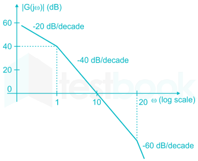
The asymptotic Bode magnitude plot of a minimum phase transfer function G(s) is shown below.

Consider the following two statements.

Statement I: Transfer function G(s) has three poles and one zero.

Statement II: At very high frequency (ω→∞), the phase angle G(jω)=3π2\angle G\left( {j\omega } \right) = - \frac{{3\pi }}{2}.

Which one of the following options is correct?

  1. ((a))

    Statement I is true and statement II is false.

  2. ((b))

    Statement I is false and statement II is true.

  3. ((c))

    Both the statements are true.

  4. ((d))

    Both the statements are false.

Show Answer
Answer: ((b))

Statement I is false and statement II is true.

Form the given bode plot, we can write the transfer function as follows 

G(s)=ks(1+s)(1+s20)G\left( s \right) = \frac{k}{{s\left( {1 + s} \right)\left( {1 + \frac{s}{{20}}} \right)}}

It has 3 poles and no zeros,

So, statement I is false

At ω → ∞, the phase angle

G(jω)=π2π2π2=3π2G\left( {j\omega } \right) = - \frac{\pi }{2} - \frac{\pi }{2} - \frac{\pi }{2} = - \frac{{3\pi }}{2}

So, statement II is true

40

The transfer function of a phase lead compensator is given by

D(s)=3(s+13T)(s+1T)D\left( s \right) = \frac{{3\left( {s + \frac{1}{{3T}}} \right)}}{{\left( {s + \frac{1}{T}} \right)}}

The frequency (in rad/sec), at which ∠D(jω) is maximum, is

  1. ((a))

    3T2\sqrt {\frac{3}{{{T^2}}}}

  2. ((b))

    13T2\sqrt {\frac{1}{{3{T^2}}}}

  3. ((c))

    3T\sqrt {3T}

  4. ((d))

    3T2\sqrt {3{T^2}}

Show Answer
Answer: ((b))

13T2\sqrt {\frac{1}{{3{T^2}}}}

Concept:

The transfer function of the phase controller is given by G(s)=1+aTs1+TsG\left( s \right)=\frac{1+aTs}{1+Ts}

Where, a > 1 for phase lead controller

a < 1 for phase lag controller

Maximum phase lead/lag frequency ωm=1Ta{{\omega }_{m}}=\frac{1}{T\sqrt{a}}

Maximum phase lead/lag ϕm=tan1(a12a)=sin1(a1a+1){{\phi }_{m}}={{\tan }^{-1}}\left( \frac{a-1}{2\sqrt{a}} \right)={{\sin }^{-1}}\left( \frac{a-1}{a+1} \right)

Calculation:

D(s)=3(s+13T)(s+1T)D\left( s \right) = \frac{{3\left( {s + \frac{1}{{3T}}} \right)}}{{\left( {s + \frac{1}{T}} \right)}}

=1+3Ts1+Ts= \frac{{1 + 3Ts}}{{1 + Ts}}

It is in the form of 1+aTs1+Ts\frac{{1 + aTs}}{{1 + Ts}}

where a > 1 for lead compensator.

The frequency at maximum phase lead,

ω=1Ta=1T3=13T2\omega = \frac{1}{{T\sqrt a }} = \frac{1}{{T\sqrt 3 }} = \frac{1}{{\sqrt {3{T^2}} }}

41

Consider a state-variable model of a system

\(\left[ {\begin{array}{{20}{c}} {{{\dot x}_1}}\ {{{\dot x}_2}} \end{array}} \right] = \left[ {\begin{array}{{20}{c}} 0&1\ { - \alpha }&{ - 2\beta } \end{array}} \right]\left[ {\begin{array}{{20}{c}} {{x_1}}\ {{x_2}} \end{array}} \right] + \left[ {\begin{array}{{20}{c}} 0\ \alpha \end{array}} \right]r\)

\(y = \left[ {\begin{array}{{20}{c}} 1&0 \end{array}} \right]\left[ {\begin{array}{{20}{c}} {{x_1}}\ {{x_2}} \end{array}} \right]\)

where y is the output, and r is the input. The damping ratio ξ and the undamped natural frequency ωn (rad/sec) of the system are given by

  1. ((a))

    ξ=βα;ωn=α{\rm{\xi }} = \frac{{\rm{\beta }}}{{\sqrt \alpha }};{\omega _n} = \sqrt \alpha

  2. ((b))

    ξ=α;ωn=βα{\rm{\xi }} = \sqrt \alpha ;{\omega _n} = \frac{\beta }{{\sqrt \alpha }}

  3. ((c))

    ξ=αβ;ωn=β{\rm{\xi }} = \frac{{\sqrt \alpha }}{\beta };{\omega _n} = \sqrt \beta

  4. ((d))

    ξ=β;ωn=α{\rm{\xi }} = \sqrt \beta ;{\omega _n} = \sqrt \alpha

Show Answer
Answer: ((a))

ξ=βα;ωn=α{\rm{\xi }} = \frac{{\rm{\beta }}}{{\sqrt \alpha }};{\omega _n} = \sqrt \alpha

From the given state model

\(\begin{array}{{20}{c}} {A = \left[ {\begin{array}{{20}{c}} 0&1\ { - \alpha }&{ - 2\beta } \end{array}} \right]}&{B = \left[ {\begin{array}{{20}{c}} 0\ \alpha \end{array}} \right]}&{C = \left[ {\begin{array}{{20}{c}} 1&0 \end{array}} \right]} \end{array}\)

Transfer function = C [sI - A]-1 B + D

\(\left[ {SI - A} \right] = S\left[ {\begin{array}{{20}{c}} 1&0\ 0&1 \end{array}} \right] - \left[ {\begin{array}{{20}{c}} 0&1\ { - \alpha }&{ - 2\beta } \end{array}} \right]\)

\(= \left[ {\begin{array}{*{20}{c}} s&{ - 1}\ \alpha &{s + 2\beta } \end{array}} \right]\)

\(= {\left[ {sI - A} \right]^{ - 1}} = \frac{1}{{s\left( {s + 2\beta } \right)\alpha }}\left[ {\begin{array}{*{20}{c}} {s + 2\beta }&1\ { - \alpha }&s \end{array}} \right]\)

\(\frac{T}{F} = \frac{{\left[ {\begin{array}{{20}{c}} 1&0 \end{array}} \right]\left[ {\begin{array}{{20}{c}} {s + 2\beta }&1\ { - \alpha }&s \end{array}} \right]\left[ {\begin{array}{*{20}{c}} 0\ \alpha \end{array}} \right]}}{{\left( {s\left( {s + 2\beta } \right) + \alpha } \right)}}\)

\(= \frac{1}{{\left( {{s^2} + 2\beta s + \alpha } \right)}}\left[ {\begin{array}{{20}{c}} 1&0 \end{array}} \right]\left[ {\begin{array}{{20}{c}} \alpha \ {s\alpha } \end{array}} \right]\)

=α(s2+2βs+α)= \frac{\alpha }{{\left( {{s^2} + 2\beta s + \alpha } \right)}}

By comparing the above transfer function with the standard second order transfer function ωn2s2+2ξωns\frac{{\omega _n^2}}{{{s^2} + 2\xi {\omega _n}s}}

ωn=α{\omega _n} = \sqrt \alpha

And 2ξωn = 2

ξ=βα\Rightarrow \xi = \frac{\beta }{{\sqrt \alpha }}

42

A moving coil instrument having a resistance of 10 Ω, gives a full-scale deflection when the current is 10 mA. What should be the value of the series resistance, so that it can be used as a voltmeter for measuring potential difference up to 100 V?

  1. ((a))

    9 Ω

  2. ((b))

    99 Ω

  3. ((c))

    990 Ω

  4. ((d))

    9990 Ω

Show Answer
Answer: ((d))

9990 Ω

Concept:

To increase the range of a voltmeter, we need to the series resistance and it is given by

Rse=Rm(VVm1){R_{se}} = {R_m}\left( {\frac{V}{{{V_m}}} - 1} \right)

Where V is the required voltmeter range

Vm is the voltmeter range

Rm­ is the meter internal resistance

Calculation:

Given that, internal resistance (Rm) = 10 Ω full scale deflection (IFSD) = 10 mA

Voltage full scale deflection (VFSD) = IFSD × Rm = 100 mV

⇒ Vm = 100 mV and Rm = 10 Ω

Required potential difference (V) = 100 V

Series resistance (Rs)=(VVm1)Rm\left( {{R_s}} \right) = \left( {\frac{V}{{{V_m}}} - 1} \right){R_m}

=(100100×1031)(10)= \left( {\frac{{100}}{{100 \times {{10}^{ - 3}}}} - 1} \right)\left( {10} \right) 

= (999) (10) = 9990 Ω

43

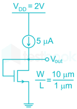
The enhancement type MOSFET in the circuit below operates according to the square law. μnCox = 100 μA/V2, the threshold voltage (VT) is 500 mV. Ignore channel length modulation. The output voltage Vout is

  1. ((a))

    100 mV

  2. ((b))

    500 mV

  3. ((c))

    600 mV

  4. ((d))

    2 V

Show Answer
Answer: ((c))

600 mV

Concept:

An enhancement type MOSFET requires some minimum Voltage (Vth) for a channel to get induced.

Linear/ Ohmic/ Triode region:

VGS > Vth

VDS < VGS – Vth

The current equation for a MOSFET in the linear region is given by:

\({{I}{D}}=k'n \frac{W}{2L}\left{2\left( {{V}{GS}}-{{V}{th}} \right){{V}{DS}}-V{DS}^{2}\right}\)

Saturation region:

VGS > Vth

VDS > VGS – Vth

The current equation for a MOSFET in the saturation region is given by:

\({I_D} = 0.5;{\mu x};c{o_x}\left( {\frac{\omega }{L}} \right){\left( {{V{GS}} - {V_T}} \right)^2}\)

where,

Vth is the minimum voltage required for the channel to get induced.

ID = Drain current

VGS = Gate to source voltage

Calculation:

Given that, μnCox = 100 μA/V2

Threshold voltage (VT) = 500 mV = 0.5 V

Vs = 0V and VD = Vout

VDS = Vout

VGS = VG - VS = Vout

VDS(sat) = VGS - Vth = V0 – 0.5 = VDS – 0.5

⇒ VDS = VDS(sat) + 0.5

⇒ VDS ⇒ VDS(sat)

So, the transistor is operating in the saturation region.

We know that,

\({I_D} = 0.5;{\mu x};c{o_x}\left( {\frac{\omega }{L}} \right){\left( {{V{GS}} - {V_T}} \right)^2}\) 

⇒ 5 × 10-6 =  0.5 × 100 × 10-6 ×10 × (VGS - 0.5)2 

(VGS0.5)2=1100⇒ {\left( {{V_{GS}} - 0.5} \right)^2} = \frac{1}{{100}}

VGS0.5=110=0.1⇒ {V_{GS}} - 0.5 = \frac{1}{{10}} = 0.1

 VGS = 0.6 = 600 mV

44

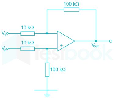
In the circuit below, the operational amplifier is ideal. If V1 = 10 mV and V2 = 50 mV, the output voltage (Vout) is

  1. ((a))

    100 mV

  2. ((b))

    400 mV

  3. ((c))

    500 mV

  4. ((d))

    600 mV

Show Answer
Answer: ((b))

400 mV

Concept: 

Virtual ground -

The concept of the virtual ground is stated as if anyone of the i/p terminals is grounded physically the other i/p terminal will also be at ground potential even though, it is not grounded physically.

  • One key feature of an Op-Amp is the differential input, and when put together in a circuit, this can form a virtual ground.
  • The virtual ground concept is helpful for the analysis of Op Amps. This concept makes Op-Amp circuit analysis much easier.

Calculation:

By applying KCL at Vb,

Vb100;k+VbV210;k=0\frac{{{V_b}}}{{100;k}} + \frac{{{V_b} - {V_2}}}{{10;k}} = 0

Vb100;k+Vb50;m10;k=0\Rightarrow \frac{{{V_b}}}{{100;k}} + \frac{{{V_b} - 50;m}}{{10;k}} = 0

Vb+10;Vb500;m=0Vb=0.511V\Rightarrow {V_b} + 10;{V_b} - 500;m = 0 \Rightarrow {V_b} = \frac{{0.5}}{{11}}V

By applying KCL at a,

VaV110;k+VaVout100;k=0\frac{{{V_a} - {V_1}}}{{10;k}} + \frac{{{V_a} - {V_{out}}}}{{100;k}} = 0

Va10;m10;k+VaVout100;k=0\Rightarrow \frac{{{V_a} - 10;m}}{{10;k}} + \frac{{{V_a} - {V_{out}}}}{{100;k}} = 0

⇒ 10 Va – 100 m + Va - Vout = 0

⇒ Vout = 11 Va – 0.1

Va=Vb=0.511V{V_a} = {V_b} = \frac{{0.5}}{{11}}V

Vout=11(0.511)0.1=0.4=400;mV\Rightarrow {V_{out}} = 11\left( {\frac{{0.5}}{{11}}} \right) - 0.1 = 0.4 = 400;mV

45

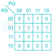
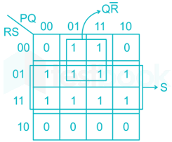
The output expression for the Karnaugh map shown below is

  1. ((a))

    QRˉ+SQ\bar R + S

  2. ((b))

    QRˉ+SˉQ\bar R + \bar S

  3. ((c))

    QR+SQR + S

  4. ((d))

    QR+SˉQR + \bar S

Show Answer
Answer: ((a))

QRˉ+SQ\bar R + S

Output = S + QR̅

46

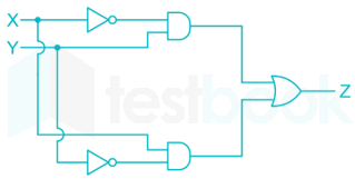
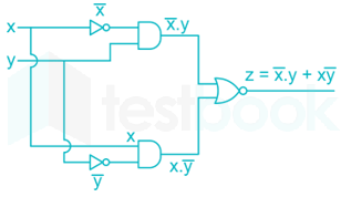
In the circuit shown below, X and Y are digital inputs, and Z is a digital output. The equivalent circuit is a

  1. ((a))

    NAND gate

  2. ((b))

    NOR gate

  3. ((c))

    XOR gate

  4. ((d))

    XNOR gate

Show Answer
Answer: ((c))

XOR gate

Concept:

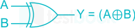
XOR GATE

Symbol:

Truth Table:

Input AInput BOutput Y = A ⊕ B
000
011
101
110

Output Equation: Y=AB=AˉB+ABˉY = {\bf{A}} \oplus {\bf{B}} = \bar AB + A\bar B

Calculation:

Z = X̅Y + XY̅

The output represents the equation of the XOR gate.

47

A DC-DC buck converter operates in continuous conduction mode. It has 48 V input voltage, and it feeds a resistive load of 24 Ω. The switching frequency of the converter is 250 Hz. If switch-on duration is 1 ms, the load power is

  1. ((a))

    6 W

  2. ((b))

    12 W

  3. ((c))

    24 W

  4. ((d))

    48 W

Show Answer
Answer: ((c))

24 W

Concept:

Concept:

In a buck converter (step down chopper)

V0=tonTVi{V_0} = \frac{{{t_{on}}}}{T}{V_i}

Also (D)=tonT\left( D \right) = \frac{{{t_{on}}}}{T}

Load power (P0)=V0I0\left( {{P_0}} \right) = {V_0}{I_0}

Where,

D = Duty ratio

V0 = Average out-put voltage or DC output voltage

Vi = Input voltage

ton = On time period

T = total time period

I0= output current

Calculation:

Given that, input voltage (VS) = 48 V

Resistive load (R) = 24 Ω

Switching frequency (f) = 250 Hz

Time period (T)=1f=1250=4;ms\left( T \right) = \frac{1}{f} = \frac{1}{{250}} = 4;ms

Switch on duration = 1 ms

Duty cycle ratio δ = ON duration / Time period

δ = 1 / 4 = 0.25

In a buck converter,

Output voltage (Vo)rmsδ\sqrt{\delta } Vs0.25×48=24\sqrt{0.25}\times48=24

Load power= (Vo)rms2R\frac{(Vo)^{2}_{rms}}{R}24224=24 W\frac{24^{2}}{24}=24 \ W

or

Output voltage (Vo)avg = δ Vs = 0.25 × 48 = 12 V

Output current (I0)avg=V0R=1224=0.5;A\left( {{I_0}} \right)avg = \frac{{{V_0}}}{R} = \frac{{12}}{{24}} = 0.5;A

Load power (P0)=V0I0=12×0.5=6;W\left( {{P_0}} \right) = {V_0}{I_0} = 12 \times 0.5 = 6;W

Note: GATE EE 2019 Official answer is both options A and C.

48

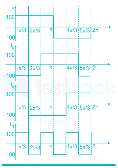
The line currents of a three-phase four wire system are square waves with amplitude of 100 A. These three currents are phase shifted by 120° with respect to each other. The rms value of neutral current is

  1. ((a))

    0 A

  2. ((b))

    1003A\frac{{100}}{{\sqrt 3 }}A

  3. ((c))

    100 A

  4. ((d))

    300 A

Show Answer
Answer: ((c))

100 A

The line currents of a three-phase four-wire system are square waves with an amplitude of 100 A.

These three currents are phase-shifted by 120° with respect to each other.

In square wave, rms value = avg value = peak value.

The neutral current is the sum of all phase currents and it is shown in the below figure.

Now, the rms value of neutral current IN=IR+IY+IB{I_N} = {I_R} + {I_Y} + {I_B}

IN=100;A{I_N} = 100;A

Note:

Don't calculate by using sinusoidal equations, the given waveform is a square wave but not sinusoidal waveform.

49

If A = 2xi + 3yj + 4zk and u = x2 + y2 + z2, then div(uA) at (1, 1, 1) is _________.

50

The probability of a resistor being defective is 0.02. There are 50 such resistors in a circuit. The probability of two or more defective resistors in the circuit (round off to two decimal places) is ______________.

51

A 0.1 μF capacitor charged to 100 V is discharged through a 1 kΩ resistor. The time in ms (round off to two decimal places) required for the voltage across the capacitor to drop to 1 V is ___________.

52

The current I flowing in the circuit shown below in amperes is ________.

53

The voltage across and the current through a load are expressed as follows

v(t)=170sin(377tπ6)Vv\left( t \right) = - 170\sin \left( {377t - \frac{\pi }{6}} \right)V

i(t)=8cos(377t+π6)Ai\left( t \right) = 8\cos \left( {377t + \frac{\pi }{6}} \right)A

The average power in watts (round off to one decimal place) consumed by the load is _______.

54

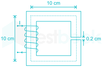
The magnetic circuit shown below has uniform cross-sectional area and air gap of 0.2 cm. The mean path length of the core is 40 cm. Assume that leakage and fringing fluxes are negligible. When the core relative permeability is assumed to be infinite, the magnetic flux density computed in the air gap is 1 tesla. With same Ampere-turns, if the core relative permeability is assumed to be 1000 (linear), the flux density in tesla (round off to three decimal places) calculated in the air gap is ___________.

55

A single-phase transformer of rating 25 kVA, supplies a 12 kW load at power factor of 0.6 lagging. The additional load at unity power factor in kW (round off to two decimal places) that may be added before this transformer exceeds its rated kVA is __________.

56

A 220 V DC shunt motor takes 3 A at no-load. It draws 25 A when running at full-load at 1500 rpm. The armature and shunt resistances are 0.5 Ω and 220 Ω, respectively. The no- load speed in rpm (round off to two decimal places) is ________.

57

A delta-connected, 3.7 kW, 400 V(line), three-phase, 4-pole, 50-Hz squirrel-cage induction motor has the following equivalent circuit parameters per phase referred to the stator:

R1 = 5.39 Ω, R2 = 5.72 Ω, X1 = X2 = 8.22 Ω. Neglect shunt branch in the equivalent circuit. The starting line current in amperes (round off to two decimal places) when it is connected to a 100 V (line), 10 Hz, three-phase AC source is _______ .

58

A 220 V (line), three-phase, Y-connected, synchronous motor has a synchronous impedance of (0.25 + j2.5) Ω/phase. The motor draws the rated current of 10 A at 0.8 pf leading. The rms value of line-to-line internal voltage in volts (round off to two decimal places) is __________.

59

A three-phase 50 Hz, 400 kV transmission line is 300 km long. The line inductance is 1 mH/km per phase, and the capacitance is 0.01 μF/km per phase. The line is under open circuit condition at the receiving end and energized with 400 kV at the sending end, the receiving end line voltage in kV (round off to two decimal places) will be ___________.

60

A 30 kV, 50 Hz, 50 MVA generator has the positive, negative, and zero sequence reactance’s of 0.25 pu, 0.15 pu, and 0.05 pu, respectively. The neutral of the generator is grounded with a reactance so that the fault current for a bolted LG fault and that of a bolted three-phase fault at the generator terminal are equal. The value of grounding reactance in ohms (round off to one decimal 

61

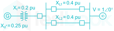
In the single machine infinite bus system shown below, the generator is delivering the real power of 0.8 pu at 0.8 power factor lagging to the infinite bus. The power angle of the generator in degrees (round off to one decimal place) is _________.

62

In a 132 kV system, the series inductance up to the point of circuit breaker location is 50 mH. The shunt capacitance at the circuit breaker terminal is 0.05 μF. The critical value of resistance in ohms required to be connected across the circuit breaker contacts which will give no transient oscillation is_______.

63

In a DC-DC boost converter, the duty ratio is controlled to regulate the output voltage at 48 V. The input DC voltage is 24 V. The output power is 120 W. The switching frequency is 50 kHz. Assume ideal components and a very large output filter capacitor. The converter operates at the boundary between continuous and discontinuous conduction modes. The value of the boost inductor (in μH) is _______.

64

A fully-controlled three-phase bridge converter is working from a 415 V, 50 Hz AC supply. It is supplying constant current of 100 A at 400 V to a DC load. Assume large inductive smoothing and neglect overlap. The rms value of the AC line current in amperes (round off to two decimal places) is ________.

65

A single-phase fully-controlled thyristor converter is used to obtain an average voltage of 180 V with 10 A constant current to feed a DC load. It is fed from single-phase AC supply of 230 V, 50 Hz. Neglect the source impedance. The power factor (round off to two decimal places) of AC mains is ________.

Attempt this paper under real exam conditions

Timed interface, section switching, instant scoring, and question-by-question analytics — free.

Start Timed Attempt