Official Paper

GATE EE 2017 Official Paper: Shift 1 (Previous Year Paper)

65 questions · 180 minutes · with answers · free

General Aptitude (10 questions)

1

After Rajendra Chola returned from his voyage to Indonesia, he _______ to visit the temple in Thanjavur.

  1. ((a))

    Was wishing

  2. ((b))

    Is wishing

  3. ((c))

    Wished

  4. ((d))

    Had wished

Show Answer
Answer: ((c))

Wished

The sentence is in the simple past tense ('returned').

Option 1 is incorrect as it is in the past continuous tense.

Option 2 is incorrect as it is in the present continuous tense.

Option 4 is incorrect as it is in the past perfect tense.

Correct option is 3, 'wished' as it is in the simple past tense.

2

Research in the workplace reveals that people work for many reasons_________.

  1. ((a))

    Money beside

  2. ((b))

    Beside money

  3. ((c))

    Money besides

  4. ((d))

    Besides money

Show Answer
Answer: ((d))

Besides money

Beside means at the side of; next to.

Besides means in addition to; apart from.

The sentence is trying to convey that research in the workplace reveals that people work for many reasons in addition to money.

Therefore options 1 and 2 are incorrect.

Option 3 is rejected as it implies 'Money in addition to' instead of the required meaning which is 'in addition to money'.

Option 4 is correct.

3

Rahul, Murali, Srinivas and Arul are seated around a square table. Rahul is sitting to the left of Murali. Srinivas is sitting to the right of Arul. Which of the following pairs are seated opposite each other?

  1. ((a))

    Rahul and Murali

  2. ((b))

    Srinivas and Anil

  3. ((c))

    Srinivas and Murali

  4. ((d))

    Srinivas and Rahul

Show Answer
Answer: ((c))

Srinivas and Murali

Rahul, Murali, Srinivas and Arul are seated around a square table.

Rahul is sitting to the left of Murali.

Srinivas is sitting to the right of Arul.

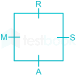
By using the above information, the seating arrangement is shown below.

Srinivas and Murali, Rahul and Arul are seated opposite to each other.

4

Find the smallest number y such that y × 162 is a perfect cube.

  1. ((a))

    24

  2. ((b))

    27

  3. ((c))

    32

  4. ((d))

    36

Show Answer
Answer: ((d))

36

162 = 2 × 81 = 2 × 34 = 2 × 3 × 33 = 6 × 33

y × 162 = y × 6 × 33

It will perfect cube at y = 62 = 36.

5

The probability that a k-digit number does NOT contain the digits 0, 5, or 9 is

  1. ((a))

    0.3k

  2. ((b))

    0.6k

  3. ((c))

    0.7k

  4. ((d))

    0.9k

Show Answer
Answer: ((c))

0.7k

We can fill each digit in a k-digit number from the numbers {1, 2, 3, 4, 6, 7, 8} as it does not contain the digit 0, 5 or 9.

So, seven numbers are available to fill each digit.

The probability to fill each digit = 7/10 = 0.7

The probability to fill all the k digits = 0.7k

6

“The hold of the nationalist imagination on our colonial past is such that anything inadequately or improperly nationalist is just not history.”

Which of the following statements best reflects the author’s opinion?

  1. ((a))

    Nationalists are highly imaginative

  2. ((b))

    History is viewed through the filter of nationalism

  3. ((c))

    Our colonial past never happened

  4. ((d))

    Nationalism has to be both adequately and properly imagined

Show Answer
Answer: ((b))

History is viewed through the filter of nationalism

The given sentence means that our knowledge of our colonial past is subject to nationalist imagination in such a way that whatever is inadequately or improperly nationalist is not considered a part of history.

Now, options 1, 3, and 4 are rejected because they do not agree with the author's opinion.

Option 2 is correct as it is closest in meaning to the author's opinion.

7

Six people are seated around a circular table. There are at least two men and two women. There are at least three right-handed persons. Every woman has a left-handed person to her immediate right. None of the women are right-handed. The number of women at the table is

  1. ((a))

    2

  2. ((b))

    3

  3. ((c))

    4

  4. ((d))

    Cannot be determined

Show Answer
Answer: ((a))

2

There are at least two men and two women.

There are at least three right-handed persons.

None of the women are right-handed.

So, number of women = 2 or 3

Every woman has a left-handed person to her immediate right.

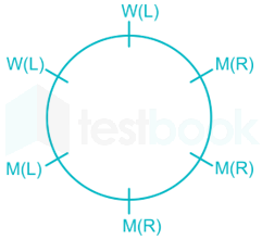
The arrangement based on the given information is as shown below.

The number of women = 2 (as every woman has a left-handed person to her immediate right)

8

The expression (x+y)xy2\frac{{\left( {x + y} \right) - \left| {x - y} \right|}}{2} is equal to

  1. ((a))

    the maximum of x and y

  2. ((b))

    the minimum of x and y

  3. ((c))

    2

  4. ((d))

    none of the above

Show Answer
Answer: ((b))

the minimum of x and y

Case 1: When x > y

(x+y)xy2=(x+y)(xy)2=y\frac{{\left( {x + y} \right) - \left| {x - y} \right|}}{2} = \frac{{\left( {x + y} \right) - \left( {x - y} \right)}}{2} = y

Case 2: When x < y

(x+y)xy2=(x+y)(yx)2=x\frac{{\left( {x + y} \right) - \left| {x - y} \right|}}{2} = \frac{{\left( {x + y} \right) - \left( {y - x} \right)}}{2} = x

The given function can be written as

\(\frac{{\left( {x + y} \right) - \left| {x - y} \right|}}{2} = \left{ {\begin{array}{*{20}{c}} {y,;x > y}\ {x,;x < y} \end{array}} \right.\)

So, the given expression is equal to the minimum of x and y.

9

Arun, Gulab, Neel and Shweta must choose one shirt each from a pile of four shirts coloured red, pink, blue and white respectively. Arun dislikes the colour red and Shweta dislikes the colour white, Gulab and Neel like all the colours. In how many different ways can they choose the shirts so that no one has a shirt with a colour he or she dislikes?

  1. ((a))

    21

  2. ((b))

    18

  3. ((c))

    16

  4. ((d))

    14

Show Answer
Answer: ((d))

14

From the given information,

Person/ColourRedPinkBlueWhite
Arun×yesyesyes
Gulabyesyesyesyes
Neelyesyesyesyes
Shwetayesyesyes×


Arun and Shweta can choose a shirt from three shirts whereas Gulab and Neel can choose a shirt from all four shirts.

Total number of possible ways to choose shirts = 3 + 4 + 4 + 3 = 14

10

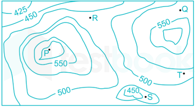
A contour line joins locations having the same height above the mean sea level. The following is a contour plot of a geographical region. Contour lines are shown at 25m intervals in this plot. If in a flood, the water level rises to 525m. Which of the villages P, Q, R, S, T get submerged?

  1. ((a))

    P, Q

  2. ((b))

    P, Q, T

  3. ((c))

    R, S, T

  4. ((d))

    Q, R, S

Show Answer
Answer: ((c))

R, S, T

From the diagram, the heights of different locations are as follows:

Location P – higher than 575 m

Location Q – Between 525 m and 550 m

Location R – Between 475 m and 500 m

Location S – Between 450 m and 475 m

Location T – Between 500 m and 525 m

Water level rises to 525 m.

Villages R, S and T having the height less than 525 m.

So, villages R, S and T get submerged.

Electrical Engineering (55 questions)

11

The matrix \(A = \left[ {\begin{array}{{20}{c}} {\frac{3}{2}}&0&{\frac{1}{2}}\ 0&{ - 1}&0\ {\frac{1}{2}}&0&{\frac{3}{2}} \end{array}} \right]\) has three distinct Eigen values and one of its Eigen vectors is \(\left[ {\begin{array}{{20}{c}} 1\ 0\ { 1} \end{array}} \right]\). Which one of the following can be another Eigen vector of A?

  1. ((a))

    \(\left[ {\begin{array}{*{20}{c}} 0\ 0\ { - 1} \end{array}} \right]\)

  2. ((b))

    \(\left[ {\begin{array}{*{20}{c}} { - 1}\ 0\ 0 \end{array}} \right]\)

  3. ((c))

    \(\left[ {\begin{array}{*{20}{c}} 1\ 0\ { - 1} \end{array}} \right]\)

  4. ((d))

    \(\left[ {\begin{array}{*{20}{c}} 1\ { - 1}\ 1 \end{array}} \right]\)

Show Answer
Answer: ((c))

\(\left[ {\begin{array}{*{20}{c}} 1\ 0\ { - 1} \end{array}} \right]\)

Concept:

If the matrix is symmetric then the product of transpose of one eigenvector to the other eigenvector should be zero. 

Calculation:

The eigenvectors of a symmetric matrix A corresponding to different eigenvalues are orthogonal to each other.

The given matrix,

\(A = \left[ {\begin{array}{*{20}{c}} {\frac{3}{2}}&0&{\frac{1}{2}}\ 0&{ - 1}&0\ {\frac{1}{2}}&0&{\frac{3}{2}} \end{array}} \right]\)

AT = A

Hence A is a symmetric matrix.

\({\left[ {\begin{array}{{20}{c}} { 1}\ 0 \1 \end{array}} \right]^T} = ;\left[ {\begin{array}{{20}{c}} { 1}&0&1 \end{array}} \right]\)

Option 3:

\(\left[ {\begin{array}{{20}{c}} { 1}&0 &1 \end{array}} \right]\left[ {\begin{array}{{20}{c}} {1}\ 0 \-1\end{array}} \right] = \left[ {1 + 0 -1} \right] = \left[ 0 \right];\)

Therefore \(\left[ {\begin{array}{*{20}{c}} 1\ 0\ { - 1} \end{array}} \right]\)can be another Eigenvector of A.

12

For a complex number z, \(\begin{array}{*{20}{c}} {lim}\ {z \to i} \end{array}\frac{{{z^2} + 1}}{{{z^3} + 2z - i\left( {{z^2} + 2} \right)}}\) is

  1. ((a))

    -2i

  2. ((b))

    -i

  3. ((c))

    i

  4. ((d))

    2i

Show Answer
Answer: ((d))

2i

\(\begin{array}{*{20}{c}} {lim}\ {z \to i} \end{array}\frac{{{z^2} + 1}}{{{z^3} + 2z - i\left( {{z^2} + 2} \right)}}\)

\(\begin{array}{*{20}{c}} {lim}\ {z \to i} \end{array}\frac{{{z^2} - (i)^2}}{{z({z^2} + 2)- i\left( {{z^2} + 2} \right)}}\)

\(\begin{array}{*{20}{c}} {lim}\ {z \to i} \end{array};\frac{{\left( {z + i} \right)\left( {z - i} \right)}}{{\left( {z - i} \right)\left( {{z^2} + 2} \right)}}\)

\( = \begin{array}{*{20}{c}} {lim}\ {z \to i} \end{array}\frac{{\left( {z + i} \right)}}{{\left( {{z^2} + 2} \right)}} \)

=i+ii2+2= \frac{{i + i}}{{{i^2} + 2}}

= 2i

13

Let z(t) = x(t) * y(t), where “ * ” denotes convolution. Let c be a positive real-valued constant. Choose the correct expression for z(ct).

  1. ((a))

    c . x(ct) * y(ct)

  2. ((b))

    x(ct) * y(ct)

  3. ((c))

    c . x(t) * y(ct)

  4. ((d))

    c . x(ct) * y(t)

Show Answer
Answer: ((a))

c . x(ct) * y(ct)

Given that,

z(t) = x(t) * y(t)

Apply Laplace transform,

Z(s) = X(s) . Y(s)

Now apply time scaling property,

z(ct)1cZ(sc)z\left( {ct} \right) \leftrightarrow \frac{1}{c}Z\left( {\frac{s}{c}} \right)

z(ct)1cX(sc);Y(sc)z\left( {ct} \right) \leftrightarrow \frac{1}{c}X\left( {\frac{s}{c}} \right);Y\left( {\frac{s}{c}} \right)

z(ct)1cX(sc)×c.1cY(sc)z\left( {ct} \right) \leftrightarrow \frac{1}{c}X\left( {\frac{s}{c}} \right)\times c.\frac{1}{c}Y\left( {\frac{s}{c}} \right)

Apply inverse Laplace

z(ct) = c x(ct) * y(ct)

14

A solid iron cylinder is placed in a region containing a uniform magnetic field such that the cylinder axis is parallel to the magnetic field direction. The magnetic field lines inside the cylinder will

  1. ((a))

    bend closer to the cylinder axis

  2. ((b))

    bend farther away from the axis

  3. ((c))

    remain uniform as before

  4. ((d))

    cease to exist inside the cylinder

Show Answer
Answer: ((a))

bend closer to the cylinder axis

A solid iron cylinder is placed in a region containing a uniform magnetic field such that the cylindrical axis is parallel to the magnetic field direction flux always flows through the low reluctance path.

Hence the magnetic field lines inside the cylinder will bend closer to the cylindrical axis.

15

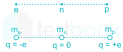
Consider an electron, a neutron and a proton initially at rest and placed along a straight line such that the neutron is exactly at the centre of the line joining the electron and proton. At t = 0 , the particles are released but are constrained to move along the same straight line. Which of these will collide first?

  1. ((a))

    the particles will never collide

  2. ((b))

    all will collide together

  3. ((c))

    proton and neutron

  4. ((d))

    electron and neutron

Show Answer
Answer: ((d))

electron and neutron

CONCEPT:

Coulomb’s Law:

It governs the electrostatic force of attraction between two charges and states that " the force of attraction between the two charges is directly proportional product of charges and the inversely proportional square of the distance between them and is given by

F=14πϵ0q1q2r2\Rightarrow F = \frac{1}{4\pi \epsilon_{0}}\frac{q_{1}q_{2}}{r^{2}}

Where q1 = First charge, q2 = Second charge, r = Distance between them 

Calculation:

Force, F=e24πεor2F = \frac{{ - {e^2}}}{{4\pi {\varepsilon _o}{r^2}}} 

Acceleration, q=Fmq = \frac{F}{m}

as me < < mp, qe > > qp

Due to this force, the electron and proton will move towards each other. Since the speed of the electron is much higher than the proton, the electron will collide with the neutron.

16

The transfer function of a system is given by,

V0(s)Vi(s)=1s1+s\frac{{{V_0}\left( s \right)}}{{{V_i}\left( s \right)}} = \frac{{1 - s}}{{1 + s}}

Let the output of the system be v0(t)=Vmsin(ωt+ϕ){v_0}\left( t \right) = {V_m}\sin \left( {\omega t + \phi } \right) for the input, vi(t)=Vmsin(ωt){v_i}\left( t \right) = {V_m}\sin \left( {\omega t} \right). Then the minimum and maximum values of ϕ (in radians) are respectively

  1. ((a))

    π2;andπ2- \frac{\pi }{2};and\frac{\pi }{2}

  2. ((b))

    π2;and;0- \frac{\pi }{2};and;0

  3. ((c))

    0;andπ20;and\frac{\pi }{2}

  4. ((d))

    π;and;0- \pi ;and;0

Show Answer
Answer: ((d))

π;and;0- \pi ;and;0

Transfer function,

Vo(s)Vi(s)=1s1+s\frac{{{V_o}\left( s \right)}}{{{V_i}\left( s \right)}} = \frac{{1 - s}}{{1 + s}}

Vi (t) = Vm sin(ωt)

Vo (t) = Vm sin(ωt + ϕ)

Here, ϕ = tan-1 (-ω) - tan-1(ω)

= - tan1(ω) - tan-1 (ω)

= - 2 tan-1(ω)

At ω = 0, 

⇒ ϕ = - 2 tan-1(0) = 0 (since tan-1(0) = 0 )

At ω = ∞,

⇒ - 2 tan-1(∞) = - 2 × π/2 = - π (since tan-1(∞) = π/2)

Range of ϕ = (-π, 0)

17

Consider the system with following input-output relation

y[n]=[1+(1)n]x[n]y\left[ n \right] = \left[ {1 + {{\left( { - 1} \right)}^n}} \right]x\left[ n \right]

where, x[n] is the input and y[n] is the output. The system is

  1. ((a))

    invertible and time invariant

  2. ((b))

    invertible and time varying

  3. ((c))

    non-invertible and time invariant

  4. ((d))

    non-invertible and time varying

Show Answer
Answer: ((d))

non-invertible and time varying

Given that, y[n] = (1 + (-1)n) x [n]

y[n - n0] = [1 + (-1)n - n0] x[n - n0]        ----(1)

y[n] = (1 + (-1)n) x[n - n0]       ----(2)

Both the equations 1 and 2 are not equal. Hence y[n] is dependent on time. It is time variant.

For invertible systems, for each unique input x[n], there should be unique output y[n].

If x[n] = δ [n - 1]

y[n] = (1 + (-1)n) δ [n - 1]

y[1] = 0

If x[n] = k δ [n - 1]

y [n] = [1 + (-1)n] k δ [n - 1]

y[1] = 0

Hence for the two different inputs, system producing same output. Hence system is non invertible.

18

A 4 pole induction machine is working as an induction generator. The generator supply frequency is 60 Hz. The rotor current frequency is 5 Hz. The mechanical speed of the rotor in RPM is

  1. ((a))

    1350

  2. ((b))

    1650

  3. ((c))

    1950

  4. ((d))

    2250

Show Answer
Answer: ((c))

1950

Concept:

When 3-ϕ induction machine working as an induction generator, then 

Slip (s) = =(Ns+Nr)Ns= \frac{{\left( { - {N_s} + {N_r}} \right)}}{{{N_s}}}

Where, 

N= Synchronous speed

Nr = Rotor speed

Frequency of rotor current = s × f

Where s is the slip

f is the supply frequency

Calculation:

Given that,

Supply frequency (fs) = 60 Hz

Rotor current frequency (fr) = 5 Hz

Number of poles = 4

Synchronous speed, \({{\rm{N}}{\rm{s}}} = \frac{{120{{\rm{f}}{\rm{s}}}}}{{\rm{P}}}\) 

=120×604=1800= \frac{{120 × 60}}{4} = 1800

We know that,

fr = (s) fs

⇒ 5 = (s) (60)

s=112\Rightarrow s = \frac{1}{{12}}

To work as an induction generator, rotor speed should be slip speed greater than synchronous speed, therefore 

112=1800+Nr1800\Rightarrow \frac{1}{{12}} = \frac{{ - 1800 + {N_r}}}{{1800}}

Nr = 1950 rpm

19

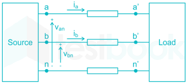
A source is supplying a load through a 2-phase, 3-wire transmission system as shown in figure below. The instantaneous voltage and current in phase-a are Van=220sin(100πt)V{V_{an}} = 220\sin \left( {100\pi t} \right)V and ia=10sin(100πt)A{i_a} = 10\sin \left( {100\pi t} \right)A respectively. Similarly, for phase-b, the instantaneous voltage and current are Vbn=220cos(100πt)V{V_{bn}} = 220\cos \left( {100\pi t} \right)V and ib=10cos(100πt)A{i_b} = 10\cos \left( {100\pi t} \right)A respectively.

The total instantaneous power flowing from the source to the load is

  1. ((a))

    2200 W

  2. ((b))

    2200 sin2(100πt) W

  3. ((c))

    4400 W

  4. ((d))

    2200 sin(100πt)cos(100πt) W

Show Answer
Answer: ((a))

2200 W

Concept:

The instantaneous power delivered to any device is given by the product of the instantaneous voltage across the device and the instantaneous current through it.

Let the voltage and current equation be

v=Vmsinωt{\rm{v}} = {{\rm{V}}_m}\sin \omega t and i=Imsin(ωtφ){\rm{i}} = {{\rm{I}}_m}\sin \left( {\omega t - \varphi } \right)

Instantaneous power at any instant is

p=v×i{\rm{p}} = {\rm{v}} \times {\rm{i}}

p=;Vmsinωt×;Imsin(ωtφ){\rm{p}} = {\rm{;}}{{\rm{V}}_m}\sin \omega t \times ;{{\rm{I}}_m}\sin \left( {\omega t - \varphi } \right)

Calculation:

Given that

Van = 220 sin (100 πt) V

ia = 10 sin (100 πt) A

Vbn = 220 cos (100 πt) V

ib = 10 cos (100 πt) A

Instantaneous power,

P = Vania + Vbnib

= 220 sin (100 πt) 10 sin (100 πt) + 220 cos (100 πt) 10 cos (100 πt)

= 2200 [sin2 (100 πt) + cos2 (100 πt)]

= 2200 W

20

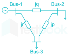
A 3-bus power system is shown in the figure below, where the diagonal elements of Y-bus matrix are: Y11 = -j12 pu, Y22 = -j15 pu and Y33 = -j7 pu.

The per unit values of the line reactances p, q and r shown in the figure are

  1. ((a))

    p = -0.2, q = -0.1, r = -0.5

  2. ((b))

    p = 0.2, q = 0.1, r = 0.5

  3. ((c))

    p = -5, q = -10, r = -2

  4. ((d))

    p = 5, q = 10, r = 2

Show Answer
Answer: ((b))

p = 0.2, q = 0.1, r = 0.5

Form the given 3-bus power system.

y12=jq,;y13=jr,y23=jp{y_{12}} = \frac{{ - j}}{q},;{y_{13}} = \frac{{ - j}}{r},{y_{23}} = \frac{{ - j}}{p}

Y11=jq+(jr)=j(1q+1r)=j12{Y_{11}} = \frac{{ - j}}{q} + \left( {\frac{{ - j}}{r}} \right) = - j\left( {\frac{1}{q} + \frac{1}{r}} \right) = - j12

1q+1r=12\Rightarrow \frac{1}{q} + \frac{1}{r} = 12        ----(1)

Y22=jq+(jP)=j(1q+1p)=j15{Y_{22}} = \frac{{ - j}}{q} + \left( {\frac{{ - j}}{P}} \right) = - j\left( {\frac{1}{q} + \frac{1}{p}} \right) = - j15

1q+1p=15 \Rightarrow \frac{1}{q} + \frac{1}{p} = 15        ----(2)

Y33=jr+(jp)=j(1r+1p)=j7{Y_{33}} = \frac{{ - j}}{r} + \left( {\frac{{ - j}}{p}} \right) = - j\left( {\frac{1}{r} + \frac{1}{p}} \right) = - j7

1r+1p=7\Rightarrow \frac{1}{r} + \frac{1}{p} = 7       ----(3)

By solving (1) and (2)

1r1p=3\frac{1}{r} - \frac{1}{p} = - 3        ----(4)

By solving (3) and (4)

2r=4r=0.5\frac{2}{r} = 4 \Rightarrow r = 0.5

p=15=0.2\Rightarrow p = \frac{1}{5} = 0.2

⇒ q = 0.1

21

A closed loop system has the characteristic equation given by s3 + Ks2 + (K + 2)s + 3 = 0. For this system to be stable, which one of the following conditions should be satisfied?

  1. ((a))

    0 < K < 0.5

  2. ((b))

    0.5 < K < 1

  3. ((c))

    0 < K < 1

  4. ((d))

    K > 1

Show Answer
Answer: ((d))

K > 1

Given that characteristic equation is,

s3 + Ks2 + (K + 2)s + 3 = 0

\(\left. {\begin{array}{{20}{c}} {{s^3}}\ {{s^2}}\ {{s^1}}\ {{s^0}} \end{array}} \right|\begin{array}{{20}{c}} 1&{\left( {K + 2} \right)}\ k&3\ {\frac{{K\left( {K + 2} \right) - 3}}{K}}&0\ 3&{} \end{array}\)

For system to be stable,

K > 0, K (K + 2) - 3 > 0

⇒ K > 0, K2 + 2K - 3 > 0

⇒ K > 0, (K + 3) (K - 1) > 0

⇒ K > 0, K > -3, K > 1 ⇒ K > 1

22

The slope and level detector circuit in a CRO has a delay of 100 ns. The start-stop sweep generator has a response time of 50 ns. In order to display correctly, a delay line of

  1. ((a))

    150 ns has to be inserted into the y-channel

  2. ((b))

    150 ns has to be inserted into the x-channel

  3. ((c))

    150 ns has to be inserted into both x and y channel

  4. ((d))

    100 ns has to be inserted into both x and y channel

Show Answer
Answer: ((a))

150 ns has to be inserted into the y-channel

The slope level detector circuit’s delay = 100 ns

The start-stop sweep generator response time = 50 ns

Total delay = 100 ns + 50 ns = 150 ns.

Sweep generator is applied across horizontal plate and unknown input is applied across vertical plate.

Hence to display correctly, a delay line of 150 ns has to be inserted into vertical plate (or) y-channel

23

The Boolean expression AB + AC̅ + BC simplifies to

  1. ((a))

    BC + AC̅

  2. ((b))

    AB + AC̅ + B

  3. ((c))

    AB + AC̅

  4. ((d))

    AB + BC

Show Answer
Answer: ((a))

BC + AC̅

Concept:

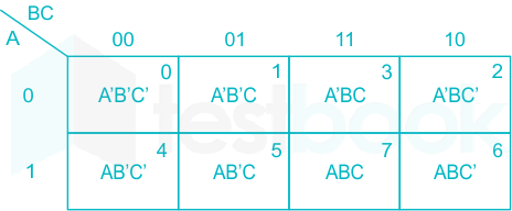
3 variable K-maps:

  • For a 3-variable Boolean function, there is a possibility of 8 output minterms.
  • The general representation of all the minterms using 3-variables is shown below.

Calculation:

Given Boolean expression is,

F = AB + AC̅ + BC

= A B C̅ + A B C + A B̅ C̅ + A B C̅ + A B C + A̅ B C

=(m6,;m7,;m4,;m6,;m7,;m3)= \sum \left( {{m_6},;{m_7},;{m_4},;{m_6},;{m_7},;{m_3}} \right)

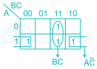
=(m3,;m4,;m6,;m7)= \sum \left( {{m_3},;{m_4},;{m_6},;{m_7}} \right)

F = BC + AC̅

24

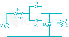
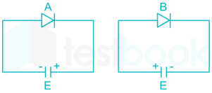
For the circuit shown in the figure below, assume that D1, D2 and D3 are ideal. v(t) = π sin (100πt) V

The DC components of voltages v1 and v2, respectively are

  1. ((a))

    0 V and 1 V

  2. ((b))

    -0.5 V and 0.5 V

  3. ((c))

    1 V and 0.5 V

  4. ((d))

    1 V and 1 V

Show Answer
Answer: ((b))

-0.5 V and 0.5 V

Concept:

Forward Bias: When the p-type side of the diode is connected to a higher potential than the n-type side, the diode is said to be forward-biased i.e., ON

Reverse Bias: When the case is opposite and n-type side is kept at a higher potential than the p-type side i.e., OFF

Analysis:

At positive pulse, D1 is ON, D2 is OFF and D3 is OFF.

and in the negative half cycle, D1 is OFF and D2 and D3 are ON. The circuit acts as a half-wave rectifier. 

The output of the half-wave rectifier circuit will be:

=Vmπ= \frac{{{V_m}}}{\pi }

For positive pulse:

V1=Vm2π,;V2=Vm2π{V_1} = \frac{{{V_m}}}{{2\pi }},;{V_2} = \frac{{{V_m}}}{{2\pi }}

V1=π2π,;V2=π2π{V_1} = \frac{\pi }{{2\pi }},;{V_2} = \frac{\pi }{{2\pi }}

For negative pulse, D1 is OFF, D2 is ON and D3 is ON. Hence resister across D3 gets short-circuited. total voltage appears across the first resistor.

V1=ππ,;V2=0{V_1} = \frac{{ - \pi }}{\pi },;{V_2} = 0

V1=π2π+(ππ)=0.5;V \Rightarrow {V_1} = \frac{\pi }{{2\pi }} + \left( {\frac{{ - \pi }}{\pi }} \right) = - 0.5;V
V2=π2π+0=0.5;V{{\rm{V}}_2} = \frac{{\rm{\pi }}}{{2{\rm{\pi }}}} + 0 = 0.5{\rm{;V}}

25

For the power semiconductor devices IGBT, MOSFET, Diode and Thyristor, which one of the following statements is TRUE?

  1. ((a))

    All the four are majority carrier devices.

  2. ((b))

    All the four are minority carrier devices.

  3. ((c))

    IGBT and MOSFET are majority carrier devices, whereas Diode and Thyristor are minority carrier devices.

  4. ((d))

    MOSFET is majority carrier device, whereas IGBT, Diode Thyristor are minority carrier devices.

Show Answer
Answer: ((d))

MOSFET is majority carrier device, whereas IGBT, Diode Thyristor are minority carrier devices.

In majority carrier devices conduction is only because of majority carriers whereas in minority carrier devices conduction is due to both majority and minority carriers.

  1. MOSFET is a majority carrier device.
  2. Diode is both majority and minority carrier device.
  3. Thyristor is minority carrier device
  4. IGBT is minority carrier device
26

Consider \(g\left( t \right) = \left{ {\begin{array}{*{}{}} {t - {{\lfloor}t{\rfloor}},;;t \ge 0}\ {t - {\lceil}t{\rceil},;;otherwise} \end{array}} \right.\), where t ϵ R.

Here, t{\lfloor}t{\rfloor} represents the largest integer less than or equal to t and t{\lceil}t{\rceil} denotes the smallest integer greater than or equal to t. The coefficient of the second harmonic component of the Fourier series representing g(t) is ________

27

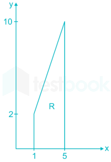
Let I=c!!!Rxy2dx;dyI = c\mathop \int!!!\int \limits_R x{y^2}dx;dy, where R is the region shown in the figure and c = 6 × 10⁻⁴. The value of I equals________. (Give the answer up to two decimal places.)

28

The power supplied by the 25 V source in the figure shown below is ________ W.
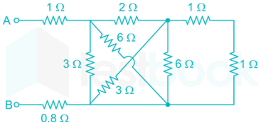
29

The equivalent resistance between the terminals A and B is ________ Ω.

30

A three-phase, 50 Hz, star-connected cylindrical-rotor synchronous machine is running as a motor. The machine is operated from a 6.6 kV grid and draws current at unity power factor (UPF). The synchronous reactance of the motor is 30 Ω per phase. The load angle is 30°. The power delivered to the motor in kW is _____________. (Give the answer up to one decimal place).

31

A 10-bus power system consists of four generator buses indexed as G1, G2, G3, G4 and six load buses indexed as L1, L2, L3, L4, L5, L6. The generator-bus G1 is considered as slack bus, and the load buses L3 and L4 are voltage-controlled buses. The generator at bus G2 cannot supply the required reactive power demand, and hence it is operating at its maximum reactive power limit. The number of non-linear equations required for solving the load flow problem using Newton-Raphson method in polar form is ___________.

32

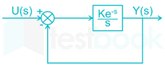
Consider the unity feedback control system shown. The value of K that results in a phase margin of the system to be 30° is __________. (Give the answer up to two decimal places.)

33

The following measurements are obtained on a single-phase load: V = 220 V ± 1%, I = 5.0 A ± 1% and W = 55 W ± 2%. If the power factor is calculated using these measurements, the worst-case error in the calculated power factor in percent is _________. (Give answer up to once decimal)

34

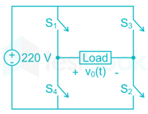
In the Inverter circuit shown below, the switches are controlled such that the load voltage v0(t) is a 400 Hz square wave.

The RMS value of the fundamental component of v0(t) in volts is _________.

35

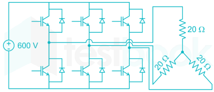
A 3-phase voltage source inverter is supplied from a 600 V DC source as shown in the figure below. For a star connected resistive load of 20 Ω per phase, the load power for 120° device conduction, in kW, is ____________.

36

A function f (x) is defined as \(f\left( x \right) = \left{ {\begin{array}{*{20}{c}} {{e^x},}&{x < 1}\ {\ln x + a{x^2}+bx,}&{x \ge 1} \end{array}} \right.\), where x ϵ R. Which one of the following statements is TRUE?

  1. ((a))

    f(x) is NOT differentiable at x = 1 for any values of a and b

  2. ((b))

    f(x) is differentiable at x = 1 for the unique value of a and b.

  3. ((c))

    f(x) is differentiable at x = 1 for all values of a and b such that a + b = e

  4. ((d))

    f(x) is differentiable at x = 1 for all values of a and b.

Show Answer
Answer: ((b))

f(x) is differentiable at x = 1 for the unique value of a and b.

Concept:

A function is said to be differentiable at x =a if,

Left derivative = Right derivative = Well defined

Analysis:

\(f\left( x \right) = \left{ {\begin{array}{*{20}{c}} {{e^x},;x < 1}\ {\log x + a{x^2} + bx,;x \ge 1} \end{array}} \right.\)

Taking Differentiation,

\(f'\left( x \right) = \left{ {\begin{array}{*{20}{c}} {{e^x},;x < 1}\ {\frac{1}{x} + 2ax + b,;x \ge 1} \end{array}} \right.\)

f’(1) = e, x < 1

f’ (1) = 1 + 2a + b, x ≥ 1

since f(x) is differentiable at x = 1,

e = 1 + 2a + b → (1)

At x = 1,

f(1) = e, x < 1

f(1) = a + b, x ≥ 1

since f(x) is continuous at x = 1,

e = a + b → (2)

From (1) and (2)

⇒ 1 + 2a + b = a + b

⇒ a = -1

⇒ b = e + 1

f(x) is differentiable at x = 1 for the unique values of a and b.

37

Consider the differential equation (t281)dydt+5ty=sin(t)\left( {{t^2} - 81} \right)\frac{{dy}}{{dt}} + 5ty = \sin \left( t \right) with y(1) = 2π. There exists a unique solution for this differential equation when t belongs to the interval

  1. ((a))

    (–2, 2)

  2. ((b))

    (–10, 10)

  3. ((c))

    (–10, 2)

  4. ((d))

    (0, 10)

Show Answer
Answer: ((a))

(–2, 2)

(t281)dydt+5ty=sin(t)\left( {{t^2} - 81} \right)\frac{{dy}}{{dt}} + 5ty = \sin \left( t \right)

dydt+5t(t281)y=sint(t281)\frac{{dy}}{{dt}} + \frac{{5t}}{{\left( {{t^2} - 81} \right)}}y = \frac{{\sin t}}{{\left( {{t^2} - 81} \right)}}

It is in the standard form of first order linear equation.

Integrating factor =e5t(t281)dt= {e^{\smallint \frac{{5t}}{{\left( {{t^2} - 81} \right)}}dt}}

=e52.2t(t281)dt= {e^{\smallint \frac{5}{2}.\frac{{2t}}{{\left( {{t^2} - 81} \right)}}dt}}

=e52ln(t281)=(t281)52= {e^{\frac{5}{2}{\rm{ln}}\left( {{t^2} - 81} \right)}} = {\left( {{t^2} - 81} \right)^{\frac{5}{2}}}

Solution of differential equation is:

y(t281)52=sint(t281).(t281)52dt+cy{\left( {{t^2} - 81} \right)^{\frac{5}{2}}} = \smallint \frac{{\sin t}}{{\left( {{t^2} - 81} \right)}}.{\left( {{t^2} - 81} \right)^{\frac{5}{2}}}dt + c

=sint(t281)32dt+c= \smallint \sin t{\left( {{t^2} - 81} \right)^{\frac{3}{2}}}dt + c

If t = ±9,

If t = ±9 then the solution is not unique hence range (-10,10), (-10, 2), (0,10) can be eliminated, then left option is (-2,2)

38

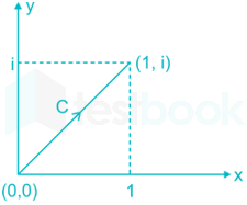
Consider the line integral \(I = \mathop \smallint \limits_C \left( {{x^2} + i{y^2}} \right)dz\), where z = x + iy. The line C is shown in figure below.

A picture containing objectDescription automatically generated

The value of I is

  1. ((a))

    12i\frac{1}{2}i

  2. ((b))

    23i\frac{2}{3}i

  3. ((c))

    34i\frac{3}{4}i

  4. ((d))

    45i\frac{4}{5}i

Show Answer
Answer: ((b))

23i\frac{2}{3}i

\(I = \mathop \smallint \limits_c^; \left( {{x^2} + i{y^2}} \right)dz\)

From the curve c,

x = y ⇒ dy = dx

z = x + iy ⇒ dz = dx + idy

\(I = \mathop \smallint \limits_0^1 \left( {{x^2} + i{x^2}} \right)\left( {dx + idx} \right)\) 

\(= \mathop \smallint \limits_0^1 {x^2}{\left( {1 + i} \right)^2}dx\) 

=(2i)(13)=2i3= \left( {2i} \right)\left( {\frac{1}{3}} \right) = \frac{{2i}}{3}

39

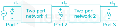
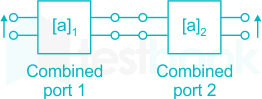
Two passive two-port networks are connected in cascade as shown in figure. A voltage source is connected at port 1.

Given V1 = A1V2 + B1I2

I1 = C1V2 + D1I2

V2 = A2V3 + B2I3

I2 = C2V3 + D2I3

A1, B1, C1, D1, A2, B2, C2, and D2 are the generalized circuit constants. If the Thevenin equivalent circuit at port 3 consists of a voltage source VT and an impedance ZT connected in series, then

  1. ((a))

    VT=V1A1A2,ZT=A1B2+B1D2A1A2+B1C2{V_T} = \frac{{{V_1}}}{{{A_1}{A_2}}},{Z_T} = \frac{{{A_1}{B_2} + {B_1}{D_2}}}{{{A_1}{A_2} + {B_1}{C_2}}}

  2. ((b))

    VT=V1A1A2+B1C2,ZT=A1B2+B1D2A1A2{V_T} = \frac{{{V_1}}}{{{A_1}{A_2} + {B_1}{C_2}}},{Z_T} = \frac{{{A_1}{B_2} + {B_1}{D_2}}}{{{A_1}{A_2}}}

  3. ((c))

    VT=V1A1+A2,ZT=A1B2+B1D2A1+A2{V_T} = \frac{{{V_1}}}{{{A_1} + {A_2}}},{Z_T} = \frac{{{A_1}{B_2} + {B_1}{D_2}}}{{{A_1} + {A_2}}}

  4. ((d))

    VT=V1A1A2+B1C2,ZT=A1B2+B1D2A1A2+B1C2{V_T} = \frac{{{V_1}}}{{{A_1}{A_2} + {B_1}{C_2}}},{Z_T} = \frac{{{A_1}{B_2} + {B_1}{D_2}}}{{{A_1}{A_2} + {B_1}{C_2}}}

Show Answer
Answer: ((d))

VT=V1A1A2+B1C2,ZT=A1B2+B1D2A1A2+B1C2{V_T} = \frac{{{V_1}}}{{{A_1}{A_2} + {B_1}{C_2}}},{Z_T} = \frac{{{A_1}{B_2} + {B_1}{D_2}}}{{{A_1}{A_2} + {B_1}{C_2}}}

Concept:

The equivalent transmission parameter for the cascade network is the product of the individual transmission parameter.

\({\left[ {\begin{array}{{20}{c}} A&B\ C&D \end{array}} \right]_{Total}} = {\left[ {\begin{array}{{20}{c}} A&B\ C&D \end{array}} \right]_1}{\left[ {\begin{array}{*{20}{c}} A&B\ C&D \end{array}} \right]_2}\)

Calculation:

We can write as follows.

\(\left[ {\begin{array}{{20}{c}} {{V_1}}\ {{I_1}} \end{array}} \right] = \left[ {\begin{array}{{20}{c}} {{A_1}}&{{B_1}}\ {{C_1}}&{{D_1}} \end{array}} \right]\left[ {\begin{array}{{20}{c}} {{A_2}}&{{B_2}}\ {{C_2}}&{{D_2}} \end{array}} \right]\left[ {\begin{array}{{20}{c}} {{V_3}}\ {{I_3}} \end{array}} \right]\)

\(\left[ {\begin{array}{{20}{c}} {{V_1}}\ {{I_1}} \end{array}} \right] = \left[ {\begin{array}{{20}{c}} {\left( {{A_1}{A_2} + {B_1}{C_2}} \right)}&{\left( {{A_1}{B_2} + {B_1}{D_2}} \right)}\ {\left( {{C_1}{A_2} + {D_1}{C_2}} \right)}&{\left( {{C_1}{B_2} + {D_1}{D_2}} \right)} \end{array}} \right]\left[ {\begin{array}{*{20}{c}} {{V_3}}\ {{I_3}} \end{array}} \right]\)

For Zth, V1 = 0

Zth=V3(I3)\Rightarrow {Z_{th}} = \frac{{{V_3}}}{{\left( { - {I_3}} \right)}}

V1 = (A1A2 + B1C2)V3 + (A1B2 + B1D2)I3 = 0

Zth=V3(I3)=A1B2+B1D2A1A2+B1C2{Z_{th}} = \frac{{{V_3}}}{{\left( { - {I_3}} \right)}} = \frac{{{A_1}{B_2} + {B_1}{D_2}}}{{{A_1}{A_2} + {B_1}{C_2}}}

For Vth, I3 = 0, V3 = Vth

V1 = (A1A2 + B1C2)Vth

Vth=V1(A1A2+B1C2)\Rightarrow {V_{th}} = \frac{{{V_1}}}{{\left( {{A_1}{A_2} + {B_1}{C_2}} \right)}}

40

Let a causal LTI system be characterized by the following differential equation, with initial rest condition

d2ydt2+7dydt+10y(t)=4x(t)+5dx(t)dt\frac{{{d^2}y}}{{d{t^2}}} + 7\frac{{dy}}{{dt}} + 10y\left( t \right) = 4x\left( t \right) + 5\frac{{dx\left( t \right)}}{{dt}}

where x(t) and y(t) are the input and output respectively. The impulse response of the system is (u(t) is the unit step function)

  1. ((a))

    2e-2tu(t) – 7 e-5tu(t)

  2. ((b))

    –2e-2tu(t) + 7 e-5tu(t)

  3. ((c))

    7e-2tu(t) – 2 e-5tu(t)

  4. ((d))

    –7e-2tu(t) + 2 e-5tu(t)

Show Answer
Answer: ((b))

–2e-2tu(t) + 7 e-5tu(t)

d2ydt2+7dydt+10y(t)=4x(t)+5dxdt\frac{{{d^2}y}}{{d{t^2}}} + 7\frac{{dy}}{{dt}} + 10y\left( t \right) = 4x\left( t \right) + 5\frac{{dx}}{{dt}}

Apply Laplace transform on both sides,

s2Y(s) + 7sY(s) + 10Y(s) = 4 X(s) + 5s X(s)

⇒ (s2 + 7s + 10) Y(s) = (4 + 5s) X(s)

Y(s)X(s)=(4+5s)s2+7s+10\Rightarrow \frac{{Y\left( s \right)}}{{X\left( s \right)}} = \frac{{\left( {4 + 5s} \right)}}{{{s^2} + 7s + 10}}

Y(s)X(s)=4+5s(s+5)(s+2)=7(s+5)2(s+2)\Rightarrow \frac{{Y\left( s \right)}}{{X\left( s \right)}} = \frac{{4 + 5s}}{{\left( {s + 5} \right)\left( {s + 2} \right)}} = \frac{7}{{\left( {s + 5} \right)}} - \frac{2}{{\left( {s + 2} \right)}}

Apply inverse laplace transform 

⇒ y(t) = 7e-5tu(t) – 2e-2t u(t)

41

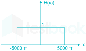
Let the signal \(x\left( t \right) = \mathop \sum \limits_{k = - \infty }^{ + \infty } {\left( { - 1} \right)^k}\delta \left( {t - \frac{k}{{2000}}} \right)\) be passed through an LTI system with frequency response H(ω), as given in the figure below.

The Fourier series coefficients of the output is given as

  1. ((a))

    4000 + 4000 cos(2000 πt) + 4000 cos(4000 πt)

  2. ((b))

    2000 + 2000 cos(2000 πt) + 2000 cos(4000 πt)

  3. ((c))

    4000 cos(2000 πt)

  4. ((d))

    2000 cos(2000 πt)

Show Answer
Answer: ((c))

4000 cos(2000 πt)

\(x\left( t \right) = \mathop \sum \limits_{k = - \infty }^\infty {\left( { - 1} \right)^k}\delta \left( {t - \frac{k}{{2000}}} \right)\)

\({C_n} = \frac{1}{{{T_0}}}\mathop \smallint \limits_0^{{T_0}} x\left( t \right){e^{ - jn{\omega _0}t}}dt\)

\({C_n} = \frac{1}{{1 \times {{10}^{ - 3}}}}\left[ {\mathop \smallint \limits_0^1 x\left( t \right){e^{ - jn{\omega _0}t}}dt} \right]\)

Cn=103[1ejnω0(0.5×10³)]{C_n} = {10^3}\left[ {1 - {e^{ - jn{\omega _0}\left( {0.5 \times {{10}^{ - 3}}} \right)}}} \right]

Cn=103[1ejn(2π1×10³)(0.5×10³)]{C_n} = {10^3}\left[ {1 - {e^{ - jn\left( {\frac{{2\pi }}{{1 \times {{10}^{ - 3}}}}} \right)\left( {0.5 \times {{10}^{ - 3}}} \right)}}} \right]

=103[1ejnπ]=103[1(1)n]= {10^3}\left[ {1 - {e^{ - jn\pi }}} \right] = {10^3}\left[ {1 - {{\left( { - 1} \right)}^n}} \right]

\(X\left( \omega \right) = 2\pi \mathop \sum \limits_{n = - \infty }^\infty {C_n}\delta \left( {\omega - n{\omega _s}} \right)\)

\(X\left( \omega \right) = 2000\pi \mathop \sum \limits_{n = - \infty }^\infty \left( {1 - {{\left( { - 1} \right)}^n}} \right)\delta \left( {\omega - 2000n\pi } \right)\)

X(ω) = 2000π […2δ(ω + 2000π) + 2δ(ω – 2000π) + …]

X(ω) = 4000 [δ(ω + 2000π) + δ(ω - 2000) + …]

X(ω) = 4000[cos (2000πt) + cos (6000πt) + …]

The output of low part filter is

Y(t) = 4000 cos (2000πt)

42

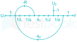
In the system whose signal flow graph is shown in the figure, U1(s) and U2(s) are inputs. The transfer function Y(s)U1(s)\frac{{Y\left( s \right)}}{{{U_1}\left( s \right)}} is

A picture containing objectDescription automatically generated

  1. ((a))

    k1JLs2+JRs+k1k2\frac{{{k_1}}}{{JL{s^2} + JRs + {k_1}{k_2}}}

  2. ((b))

    k1JLs2JRsk1k2\frac{{{k_1}}}{{JL{s^2} - JRs - {k_1}{k_2}}}

  3. ((c))

    k1U2(R+sL)JLs2+(JRU2L)s+k1k2U2R\frac{{{k_1} - {U_2}\left( {R + sL} \right)}}{{JL{s^2} + \left( {JR - {U_2}L} \right)s + {k_1}{k_2} - {U_2}R}}

  4. ((d))

    k1U2(sLR)JLs2(JR+U2L)sk1k2+U2R\frac{{{k_1} - {U_2}\left( {sL - R} \right)}}{{JL{s^2} - \left( {JR + {U_2}L} \right)s - {k_1}{k_2} + {U_2}R}}

Show Answer
Answer: ((a))

k1JLs2+JRs+k1k2\frac{{{k_1}}}{{JL{s^2} + JRs + {k_1}{k_2}}}

No. of forward paths from u1(s) to Y(s) are:

P1=(1)(1L)(1S)(K1)(1J)(1S)(1)=K1JLS2{P_1} = \left( 1 \right)\left( {\frac{1}{L}} \right)\left( {\frac{1}{S}} \right)\left( {{K_1}} \right)\left( {\frac{1}{J}} \right)\left( {\frac{1}{S}} \right)\left( 1 \right) = \frac{{{K_1}}}{{JL{S^2}}}

No. of loops are:

L1=(1L)(1S)(R)=RSL{L_1} = \left( {\frac{1}{L}} \right)\left( {\frac{1}{S}} \right)\left( { - R} \right) = \frac{{ - R}}{{SL}}

L2=(1L)(1s)(K1)(1J)(1S)(K2)=K1K2JLS2{L_2} = \left( {\frac{1}{L}} \right)\left( {\frac{1}{s}} \right)\left( {{K_1}} \right)\left( {\frac{1}{J}} \right)\left( {\frac{1}{S}} \right)\left( { - {K_2}} \right) = - \frac{{{K_1}{K_2}}}{{JL{S^2}}}

Δ=1(L1+L2)=1+RSL+K1K2JLS2{\rm{\Delta }} = 1 - \left( {{L_1} + {L_2}} \right) = 1 + \frac{R}{{SL}} + \frac{{{K_1}{K_2}}}{{JL{S^2}}}

From Mason’s gain formula:

Transfer function \(= \frac{{\mathop \sum \nolimits_{K = 1}^n {P_K}{{\rm{\Delta }}_K}}}{{\rm{\Delta }}}\)

=K1JLS2(1)1+RSL+K1K2JLS2= \frac{{\frac{{{K_1}}}{{JL{S^2}}}\left( 1 \right)}}{{1 + \frac{R}{{SL}} + \frac{{{K_1}{K_2}}}{{JL{S^2}}}}}

Y(s)U1(s)=K1JLS2+JRS+K1K2\frac{{Y\left( s \right)}}{{{U_1}\left( s \right)}} = \frac{{{K_1}}}{{JL{S^2} + JRS + {K_1}{K_2}}}

43

The transfer function of the system Y(s)U(s)\frac{{Y\left( s \right)}}{{U\left( s \right)}} whose state-space equations are given below is:

\(\left[ {\begin{array}{{20}{c}} {{{\dot x}_1}\left( t \right)}\ {{{\dot x}_2}\left( t \right)} \end{array}} \right] = \left[ {\begin{array}{{20}{c}} 1&2\ 2&0 \end{array}} \right]\left[ {\begin{array}{{20}{c}} {{x_1}\left( t \right)}\ {{x_2}\left( t \right)} \end{array}} \right] + \left[ {\begin{array}{{20}{c}} 1\ 2 \end{array}} \right]u\left( t \right)\)

\(y\left( t \right) = \left[ {\begin{array}{{20}{c}} 1&0 \end{array}} \right]\left[ {\begin{array}{{20}{c}} {{x_1}\left( t \right)}\ {{x_2}\left( t \right)} \end{array}} \right]\)

  1. ((a))

    (s+2)(s22s2)\frac{{\left( {s + 2} \right)}}{{\left( {{s^2} - 2s - 2} \right)}}

  2. ((b))

    (s2)(s2+s4)\frac{{\left( {s - 2} \right)}}{{\left( {{s^2} + s - 4} \right)}}

  3. ((c))

    (s4)(s2+s4)\frac{{\left( {s - 4} \right)}}{{\left( {{s^2} + s - 4} \right)}}

  4. ((d))

    (s+4)(s2s4)\frac{{\left( {s + 4} \right)}}{{\left( {{s^2} - s - 4} \right)}}

Show Answer
Answer: ((d))

(s+4)(s2s4)\frac{{\left( {s + 4} \right)}}{{\left( {{s^2} - s - 4} \right)}}

From the given state space equations,

\(A = \left[ {\begin{array}{*{20}{c}} 1&2\ 2&0 \end{array}} \right]\)

\(B = \left[ {\begin{array}{*{20}{c}} 1\ 2 \end{array}} \right]\)

\(C = \left[ {\begin{array}{*{20}{c}} 1&0 \end{array}} \right]\)

Transfer function = C[sI - A]-1 B + D

\(sI - A = \left[ {\begin{array}{{20}{c}} s&0\ 0&s \end{array}} \right] - \left[ {\begin{array}{{20}{c}} 1&2\ 2&0 \end{array}} \right] = \left[ {\begin{array}{*{20}{c}} {s - 1}&{ - 2}\ { - 2}&s \end{array}} \right]\)

\({\left( {sI - A} \right)^{ - 1}} = \frac{1}{{{s^2} - s - 4}}\left[ {\begin{array}{*{20}{c}} s&2\ 2&{s - 1} \end{array}} \right]\)

Transfer function \(= \left[ {\begin{array}{{20}{c}} 1&0 \end{array}} \right]\frac{1}{{\left( {{s^2} - s - 4} \right)}}\left[ {\begin{array}{{20}{c}} s&2\ 2&{s - 1} \end{array}} \right]\left[ {\begin{array}{*{20}{c}} 1\ 2 \end{array}} \right]\)

\(= \frac{1}{{\left( {{s^2} - s - 4} \right)}}\left[ {\begin{array}{{20}{c}} s&2 \end{array}} \right]\left[ {\begin{array}{{20}{c}} 1\ 2 \end{array}} \right]\)

=s+4(s2s4)= \frac{{s + 4}}{{\left( {{s^2} - s - 4} \right)}}

44

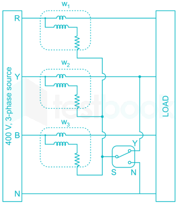
The load shown in the figure is supplied by a 400 V (line-to-line), 3-phase source (RYB sequence). The load is balanced and inductive, drawing 3464 VA. When the switch S is in position N, the three wattmeters W1, W2 and W3 read 577.35 W each. If the switch is moved to position Y, the readings of the wattmeters in watts will be:

  1. ((a))

    W1 = 1732 and W2 = W3 = 0

  2. ((b))

    W1 = 0, W2 = 1732 and W3 = 0

  3. ((c))

    W1 = 866, W2 = 0 and W3 = 866

  4. ((d))

    W1 = W2 = 0 and W3 = 1732

Show Answer
Answer: ((d))

W1 = W2 = 0 and W3 = 1732

Given that,

W1 = W2 = W3 = 577.35 W

Total power,

P = W1 + W2 + W3 = 1732 W.

VA rating = 3464 VA

P = VI cos ϕ

⇒ 1732 = 3464 cos ϕ

⇒ cos ϕ = 0.5 lag

Given, VL = 400 V

√3 VL IL cos Φ = 1732

IL=17323×400×0.5=5A\Rightarrow {I_L} = \frac{{1732}}{{\sqrt 3 \times 400 \times 0.5}} = 5A

When switch is connected from N to Y, pressure

Coil of W2 is shorted

⇒ W2 = 0 W

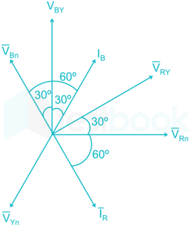
W1 = Vpc Icc cos (Vpc & Icc) = VRY IR cos (VRY & IR)

= 400 × 5 cos (90°) = 0 W

W3 = VBY IB cos (VBY & IB) = 400 × 5 × cos 30° = 1732 W

45

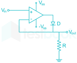
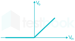
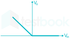
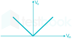
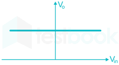
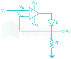
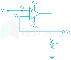
The approximate transfer characteristic for the circuit shown below with an ideal operational amplifier and diode will be

  1. ((a))

  2. ((b))

  3. ((c))

  4. ((d))

Show Answer
Answer: ((a))

For Vin > 0 V,

Va > Vb and the diode becomes ON.

Now, the circuit becomes

The above circuit represents voltage follower circuit.

So, the output voltage V0 = Vin

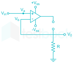
For Vin < 0 V

Va < Vb and the diode becomes OFF.

Now, the circuit becomes

Virtual Ground concept is NOT valid for open loop system.

Therefore,

V0 = 0 V

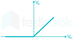
Now, the transfer characteristics for the given circuit are:

A picture containing objectDescription automatically generated

46

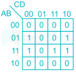
The output expression for the Karnaugh map shown below is:

A close up of a keyboardDescription automatically generated

  1. ((a))

    BD̅ + BCD

  2. ((b))

    BD̅ + AB

  3. ((c))

    B̅D + ABC

  4. ((d))

    BD̅ + ABC

Show Answer
Answer: ((d))

BD̅ + ABC

Given K-map:

A close up of a keyboardDescription automatically generated

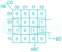
It can be grouped as follows:

Output expression in the form of SOP (sum of products) = BD̅ + ABC

47

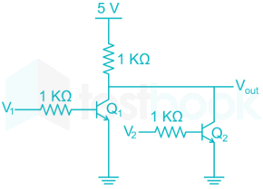
The logical gate implemented using the circuit shown below where, V1 and V2 are inputs (with 0 V as digital 0 and 5 V as digital 1) and VOUT is the output, is

A close up of a signDescription automatically generated

  1. ((a))

    NOT

  2. ((b))

    NOR

  3. ((c))

    NAND

  4. ((d))

    XOR

Show Answer
Answer: ((b))

NOR

Concept:

NOR gate: Output of this logic gate is true when both inputs are false.

Symbol:

Truth Table:

ABNANDNOR
0011
0110
1010
1100


XOR GATE

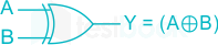
Symbol:

Truth Table:

Input AInput BOutput Y = A ⊕ B
000
011
101
110

Output Equation: Y=AB=AˉB+ABˉY = {\bf{A}} \oplus {\bf{B}} = \bar AB + A\bar B

Calculation:

Given circuit diagarm

A close up of a signDescription automatically generated

At V1 = 0, V2 = 0; both transistors are in cut off region and hence both are in OFF condition

So Vout = HIGH (1)

At V1 = 0, V2 = 1; Q1 is in OFF condition and Q2 is in ON condition.

So, Vout = LOW (0)

At V1 = 1, V2 = 0; Q1 is in ON condition and Q2 is in OFF condition.

So, Vout = LOW (0)

At V1 = 1, V2 = 1; Q1 is in ON condition and Q2 is in ON condition.

So, Vout = LOW (0)

V1V2Q1Q2Vout
00OFFOFF1
01OFFON0
10ONOFF0
11ONON0


From the above truth table, it is clear that the given logical circuit represents NOR gate.

48

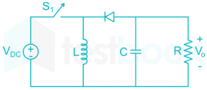
The input voltage VDC of the buck-boost converter shown below varies from 32 V to 72 V. Assume that all components are ideal, inductor current is continuous, and output voltage is ripple free. The range of duty ratio D of the converter for which the magnitude of the steady-state output voltage remains constant at 48 V is

A picture containing objectDescription automatically generated

  1. ((a))

    25D35\frac{2}{5} \le D \le \frac{3}{5}

  2. ((b))

    23D34\frac{2}{3} \le D \le \frac{3}{4}

  3. ((c))

    0 ≤ D ≤ 1

  4. ((d))

    13D23\frac{1}{3} \le D \le \frac{2}{3}

Show Answer
Answer: ((a))

25D35\frac{2}{5} \le D \le \frac{3}{5}

Concept:

For a buck-boost converter,

V0=(D1D)VDC{V_0} = \left( {\frac{D}{{1 - D}}} \right){V_{DC}}

Calculation:

Given that,

Source voltage (VDC) = 32 V to 72 V

Output voltage, (V0) = 48 V

For a buck-boost converter,

V0=(D1D)VDC{V_0} = \left( {\frac{D}{{1 - D}}} \right){V_{DC}}

Where D is duty ratio

When VDC = 32V,

48=(D1D)32\Rightarrow 48 = \left( {\frac{D}{{1 - D}}} \right)32

⇒ 3(1 - D) = 2D

D=35\Rightarrow D = \frac{3}{5}

When VDC = 72V,

48=(D1D)72\Rightarrow 48 = \left( {\frac{D}{{1 - D}}} \right)72

⇒ 2(1 - D) = 3D

D=25\Rightarrow D = \frac{2}{5}

Range of D is: 25D35\frac{2}{5} \le D \le \frac{3}{5}

49

A load is supplied by a 230 V, 50 Hz source. The active power P and the reactive power Q consumed by the load are such that 1 kW ≤ P ≤ 2 kW and 1 kVAR ≤ Q ≤ 2 kVAR. A capacitor connected across the load for power factor correction generates 1 kVAR reactive power. The worst case power factor after power factor connection is

  1. ((a))

    0.447 lag

  2. ((b))

    0.707 lag

  3. ((c))

    0.894 lag

  4. ((d))

    1

Show Answer
Answer: ((b))

0.707 lag

Given that,

Active power of load: 1 kW ≤ P ≤ 2 kW

Reactive power of load: 1 kVAR ≤ Q ≤ 2 kVAR

For worst case power factor, active power should be minimum and reactive power should be maximum.

P = 1 kW, Q = 2 kVAR

But capacitor connected across the load for power factor correction generates 1 kVAR reactive power

Now, P = 1 kW, Q = 1 kVAR

Power factor angle, ϕ=tan1(QP)=45\phi = {\tan ^{ - 1}}\left( {\frac{Q}{P}} \right) = 45^\circ

Power factor, cos ϕ = cos 45° = 0.707 lag

50

The bus admittance matrix for a power system network is

\(\left[ {\begin{array}{*{20}{c}} { - j39.9}&{j20}&{j20}\ {j20}&{ - j39.9}&{j20}\ {j20}&{j20}&{ - j39.9} \end{array}} \right]pu\)

There is a transmission line, connected between buses 1 and 3, which is represented by the circuit shown in figure.

A close up of a signDescription automatically generated

If this transmission line is removed from service, what is the modified bus admittance matrix?

  1. ((a))

    \(\left[ {\begin{array}{*{20}{c}} { - j19.9}&{j20}&0\ {j20}&{ - j39.9}&{j20}\ 0&{j20}&{ - j19.9} \end{array}} \right]pu\)

  2. ((b))

    \(\left[ {\begin{array}{*{20}{c}} { - j39.95}&{j20}&0\ {j20}&{ - j39.9}&{j20}\ 0&{j20}&{ - j39.95} \end{array}} \right]pu\)

  3. ((c))

    \(\left[ {\begin{array}{*{20}{c}} { - j19.95}&{j20}&0\ {j20}&{ - j39.9}&{j20}\ 0&{j20}&{ - j19.95} \end{array}} \right]pu\)

  4. ((d))

    \(\left[ {\begin{array}{*{20}{c}} { - j19.95}&{j20}&{j20}\ {j20}&{ - j39.9}&{j20}\ {j20}&{j20}&{ - j19.95} \end{array}} \right]pu\)

Show Answer
Answer: ((c))

\(\left[ {\begin{array}{*{20}{c}} { - j19.95}&{j20}&0\ {j20}&{ - j39.9}&{j20}\ 0&{j20}&{ - j19.95} \end{array}} \right]pu\)

Given matrix:

\({Y_{bus}} = \left[ {\begin{array}{*{20}{c}} { - j39.9}&{j20}&{j20}\ {j20}&{ - j39.9}&{j20}\ {j20}&{j20}&{ - j39.9} \end{array}} \right]pu\)

The transmission line connected between bus 1 and bus 3 is removed.

Z13 = 0.05 = Z31

y13=1Z13=10.05=j20\Rightarrow {y_{13}} = \frac{1}{{{Z_{13}}}} = \frac{1}{{0.05}} = - j20

Half-line shunt susceptance 

Y11 (old) = -j39.9 pu

Y11(new)=Y11(old)y13y132{Y_{11}}\left( {new} \right) = {Y_{11}}\left( {old} \right) - {y_{13}} - \frac{{y_{13}'}}{2}

= -j39.9 – (-j20) – j0.05

= -j 19.95 u

Y33 (old) = -j39.9 pu

Y33(new)=Y33(old)y13y132{Y_{33}}\left( {new} \right) = {Y_{33}}\left( {old} \right) - {y_{13}} - \frac{{y_{13}'}}{2}

= -j39.9 – (-j20) – j0.05

= -j19.95 pu

Y13 (old) = Y31(old) = j20 pu

Y13(new) = Y31(new) = 0 pu

Now, the modified matrix will be,

\({Y_{BUS}} = \left[ {\begin{array}{*{20}{c}} { - j19.95}&{j20}&0\ {j20}&{ - j39.9}&{j20}\ 0&{j20}&{ - j19.95} \end{array}} \right]pu\)

51

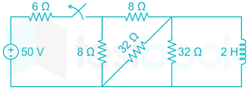
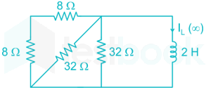
The switch in the below figure was closed for a long time. It is opened at t = 0. The current in the inductor of 2 H for t ≥ 0, is

A picture containing objectDescription automatically generated

  1. ((a))

    2.5 e-4t

  2. ((b))

    5 e-4t

  3. ((c))

    2.5 e-0.25t

  4. ((d))

    5 e-0.25t

Show Answer
Answer: ((a))

2.5 e-4t

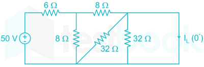
At t = 0-, inductor acts as short circuit,

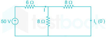
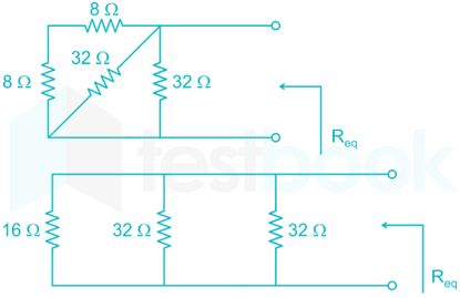
Now, the circuit is reduced to,

Equivalent resistance Req = 10 Ω

Current, I=5010=5;AI = \frac{{50}}{{10}} = 5;A

By using current division rule,

IL(0)=52=2.5;A{I_L}\left( {{0^ - }} \right) = \frac{5}{2} = 2.5;A

At t = 0+,

IL (0+) = IL (0-) = 2.5 A

At steady state (t = ∞)

Time constant of the circuit (τ)=LReq\left( τ \right) = \frac{L}{{{R_{eq}}}}

Req is the equivalent resistance across inductor.

Req = 16||32||32 = 8 Ω

Time constant: 

(τ)=LReq=28=0.25;sec\left( τ \right) = \frac{L}{{{R_{eq}}}} = \frac{2}{8} = 0.25;sec

iL(t) = iL(∞) + [iL(0+) - iL(∞)]e-t/τ

= 0 + (2.5 - 0) e-4t = 2.5 e-4t A

52

Only one of the real roots of f(x) = x6 – x – 1 lies in the interval 1 ≤ x ≤ 2 and bisection method is used to find its value. For achieving an accuracy of 0.001, the required minimum number of iterations is __________.

53

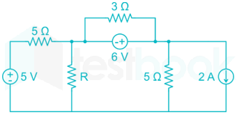
In the circuit shown below, the maximum power transferred to the resistor R is ________ W.

54

The magnitude of magnetic flux density (B) in micro Teslas (μT), at the centre of a loop of wire wound as a regular hexagon of side length 1 m carrying a current (I = 1 A ) and placed in vacuum as shown in the figure is __________. (Give the answer up to two decimal places.)

A close up of a mapDescription automatically generated

55

A 375 W, 230 V, 50 Hz, capacitor start single-phase induction motor has the following constants for the main and auxiliary windings (at starting): Zm = (12.50 + j15.75) Ω (main winding), Za = (24.50 + 12.75) Ω (auxiliary winding). Neglecting the magnetizing branch, the value of the capacitance (in μF) to be added in series with the auxiliary winding to obtain maximum torque at starting is ___________.

56

Two parallel connected, three phase, 50 Hz, 11 kV, star-connected synchronous machines A and B, are operating as synchronous condensers. They together supply 50 MVAR to a 11 kV grid. Current supplied by both the machines are equal. Synchronous reactances of machine A and machine B are 1Ω and 3Ω, respectively. Assuming the magnetic circuit to be linear, the ratio of excitation current of machine A to that of machine B is _________. (Give the answer up to two decimal places.)

57

A 220 V DC series motor runs drawing a current of 30 A from the supply. Armature and field circuit resistances are 0.4 Ω and 0.1 Ω respectively. The load torque varies as the square of the speed. The flux in the motor may be taken as being proportional to the armature current. To reduce the speed of the motor by 50%, the resistance in ohms that should be added in series with the armature is ________. (Give the answer up to two decimal places.)

58

A three-phase, three winding Δ/Δ/Y (1.1 kV/6.6 kV/400 V) transformer is energized from AC mains at the 1.1 kV side. It supplies 900 kVA load at 0.8 power factor lag from the 6.6 kV winding and 300 kVA load at 0.6 power factor lag from the 400 V winding. The RMS line current in ampere drawn by the 1.1 kV winding from the mains is ___________. (Give the answer up to one decimal place.)

59

A separately excited DC generator supplies 150 A to a 145 V DC grid. The generator is running at 800 RPM. The armature resistance of the generator is 0.1 Ω. If the speed of the generator is increased to 1000 RPM, the current in amperes supplied by the generator to the DC grid is __________. (Give the answer up to one decimal place.)

60

For a system having transfer function G(s)=s+1s+1G\left( s \right) = \frac{{ - s + 1}}{{s + 1}}, a unit step input is applied at time t = 0. The value of the response of the system at t = 1.5 sec (rounded off to three decimal places) is __________.

61

Consider a causal and stable LTI system with rational transfer function H(z), whose corresponding impulse response begins at n = 0. Furthermore, H(1)=54H\left( 1 \right) = \frac{5}{4}. The poles of H(z) are pk=12exp(j(2k1)4π){p_k} = \frac{1}{{\sqrt 2 }}\exp \left( {j\frac{{\left( {2k - 1} \right)}}{4}\pi } \right) for k = 1, 2, 3, 4. The zeros of H(z) are all at z = 0. Let g[n] = jnh[n]. The value of g[8] equals __________. (Give the answer up to three decimal places.)

62

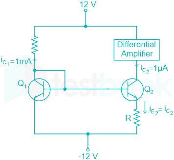
The circuit shown in the figure uses matched transistors with a thermal voltage VT = 25 mV. The base currents of the transistors are negligible. The value of the resistance R in kΩ that is required to provide 1 μA bias current for the differential amplifier block shown is ___________. (Give the answer up to one decimal place.)

63

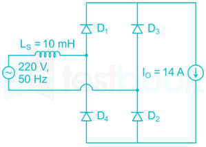
The figure below shows an uncontrolled diode bridge rectifier supplied from a 220 V, 50 Hz, 1-phase ac source. The load draws a constant current I0 = 14 A. The conduction angle of the diode D1 in degrees (rounded off to two decimal places) is ________.

64

The positive, negative, and zero sequence reactances of a wye-connected synchronous generator are 0.2 pu, 0.2 pu and 0.1 pu respectively. The generator is on open circuit with a terminal voltage of 1 pu. The minimum value of the inductive reactance, in pu, required to be connected between neutral and ground so that the fault current does not exceed 3.75 pu if a single line to ground fault occurs at the terminals is _________(assume fault impedance to be zero). (Give the answer up to one decimal place.)

65

The figure shows the single line diagram of a power system with a double circuit transmission line. The expression for electrical power is 1.5 sin δ, where δ is the rotor angle. The system is operating at the stable equilibrium point with mechanical power equal to 1 pu. If one of the transmission line circuits is removed, the maximum value of δ, as the rotor swings, is 1.221 radian. If the expression for electrical power with one transmission line circuit removed is Pmax sin δ, the value of Pmax, in pu is ______. (Give the answer up to three decimal places.)

Attempt this paper under real exam conditions

Timed interface, section switching, instant scoring, and question-by-question analytics — free.

Start Timed Attempt