Official Paper

GATE EE 2014 Official Paper: Shift 3 (Previous Year Paper)

65 questions · 180 minutes · with answers · free

General Aptitude (10 questions)

1

While trying to collect (I) an envelope from under the table (II)Mr. X fell down and (III) was losing consciousness (IV)

<br>

Which one of the above-underlined parts of the sentence is NOT appropriate?

  1. ((a))

    I

  2. ((b))

    II

  3. ((c))

    III

  4. ((d))

    IV

Show Answer
Answer: ((d))

IV

The correct answer is option 4 i.e. Mr. X fell down and was losing consciousness

Let's look at the following points-

  • The tense used in the first clause is the present progressive(continuous) tense.
  • Whereas the second clause contains simple past tense i.e. "Mr X fell down" and in **past continuous tense i.e. '**Mr. X fell down and was losing consciousness'.

Now, look at the following points-

  • When the simple past tense and the past continuous tense are used together in a sentence, it shows that the action referred to by the simple past tense takes place somewhere in the middle of the past continuous action.
  • These tenses are often used to show an action interrupting another action.
  • For e.g.- I was working when someone knocked at the door.

Explanation

Losing consciousness is an instantaneous action which cannot go on for a period of time. There is a definite 'point' where the person falls unconscious. Hence, we may conclude that in this sentence, it was an effect of Mr. X's falling down and would take the simple past tense. 

​Correct Sentence- While trying to collect an envelope from under the table, Mr. X fell down and lost consciousness.
2

If she _______ how to calibrate the instrument, she ______ done the experiment.

  1. ((a))

    knows, will have

  2. ((b))

    knew, had

  3. ((c))

    had known, could have

  4. ((d))

    should have known, would have

Show Answer
Answer: ((c))

had known, could have

The correct answer is option 3 i.e. had known, could have

The given sentence is a conditional sentence in the third conditional form. 

Let's look at the following points-

  • The given sentence is a conditional sentence, conditional sentences show a possible cause and effect situation
  • A conditional sentence has two clauses that depend on each other to make sense, Conditional clause (often referred to as if-clause) is a dependent clause and the main clause is the independent clause
  • The tense of these clauses determines the type of conditional sentence


Now look at the following point-

  • To understand the types of Conditional sentence look at the following description -
If clauseMain Clause
If + Present Indefinite TenseSimple Future tense
If + Past Indefinite TenseSubject + would + v1
If + Past Perfect TenseSubject + would/ could + have +v3


Explanation

  • The given sentence is conditional consisting of 'if clause' with a blank and 'Main clause' with a blank preceded by subject and followed by the third form of Verb,
  • As the subject and the third form of the verb are given in the 'Main clause' we can easily conclude that the Tense of the 'If clause' will be in 'Past Perfect'
  • The third type of conditional sentence has the form'-
If + past perfect Tense -------------Sub + would/ could + have + v3
  • Hence, as per the rule the correct option to be filled in the blank is had known, could have

​**Correct sentence-**If she had known how to calibrate the instrument, she could have done the experiment.

3

Choose the word that is opposite in meaning to the word “coherent”.

  1. ((a))

    Sticky

  2. ((b))

    Well-connected

  3. ((c))

    Rambling

  4. ((d))

    Friendly

Show Answer
Answer: ((c))

Rambling

The correct answer is option 3, i.e.Rambling


Explanation 

Let’s look at the meanings of the given word and the option:

  • Coherent: logical and consistent (of an argument, theory, or policy); rational, orderly, clear, methodical
  • Rambling:  lengthy and confused or inconsequential (of writing or speech); roundabout, confused, disjointed, incoherent

​​Here we find that both Coherent and Rambling express the opposite meaning

Therefore both the words are Antonyms, and thus Option 3 Rambling is the correct answer

Let's look at the meaning of the other words:

  • Sticky: Made of or covered with a substance that stays attached to any surface it touches
  • Well-connected: Acquainted with or related to people with prestige or influence
  • Friendly: Behaving in a pleasant, kind way towards someone
4

Which number does not belong in the series below?

2, 5, 10, 17, 26, 37, 50, 64

  1. ((a))

    17

  2. ((b))

    37

  3. ((c))

    64

  4. ((d))

    26

Show Answer
Answer: ((c))

64

Series: 2, 5, 10, 17, 26, 37, 50, 64

5 - 2 = 3

10 - 5 = 5

17- 10 = 7

26 - 17 = 9

37 - 26 = 11

50 - 37 = 13

64 - 50 = 14

Sinc the series created by the difference of the consecutive terms is 3, 5, 7, 9, 11, 13 

The last difference is 14 which doesn't fit in the series ∴

Therefore 64 does not belong in the series.

Correct series: 2, 5, 10, 17, 26, 37, 50, 65

5

The table below has question-wise data on the performance of students in an examination. The

marks for each question are also listed. There is no negative or partial marking in the examination.

Q No.MarksAnswered CorrectlyAnswered WronglyNot Attempted
1221176
2315272
3223183


What is the average of the marks obtained by the class in the examination?

  1. ((a))

    1.34

  2. ((b))

    1.74

  3. ((c))

    3.02

  4. ((d))

    3.91

Show Answer
Answer: ((c))

3.02

For  Q1:

Number of students Answered Correctly  = 21

Number of students Answered Wrongly  = 17

Number of students Answered Wrongly  = 6

∴ number of students = 21 + 17 + 6 = 44

Similary, for Q2 and Q3 sum will be 45

For 1st question total marks obtained = 2 × 21 = 42

For 2nd question total marks obtained = 3 × 15 = 45

For 3rd question total marks obtained = 2 × 23 = 46

Hence total marks obtained by the class are = 42+45+46 = 133

Average marks obtained = Total marksTotal students=13344\frac{Total~marks}{ Total ~ students} = \frac{133}{44}

∴ Average marks obtained = 3.02.

6

A dance programme is scheduled for 10.00 a.m. Some students are participating in the programme and they need to come an hour earlier than the start of the event. These students should be accompanied by a parent. Other students and parents should come in time for the programme. The instruction you think that is appropriate for this is

  1. ((a))

    Students should come at 9.00 a.m. and parents should come at 10.00 a.m.

  2. ((b))

    Participating students should come at 9.00 a.m. accompanied by a parent, and other parents and students should come by 10.00 a.m.

  3. ((c))

    Students who are not participating should come by 10.00 a.m. and they should not bring their parents. Participating students should come at 9.00 a.m.

  4. ((d))

    Participating students should come before 9.00 a.m. Parents who accompany them should come at 9.00 a.m. All others should come at 10.00 a.m.

Show Answer
Answer: ((b))

Participating students should come at 9.00 a.m. accompanied by a parent, and other parents and students should come by 10.00 a.m.

The correct answer is Option 2.

Explanation

Let's look at the key points from the paragraph.

  • The dance programme is scheduled for 10:00 am
  • Participating students need to come an hour early i.e. at 9:00 am with a parent.
  • Other students and parents should come on time i.e. 10:00 am for the programme.

Let's look at the options given.

  • Option 1  is wrong because parents and students who are not participating should come at 10:00 am. Only those who are participating (student along with a parent) should come at 9:00.
  • Option 2 is correct as it agrees totally with the paragraph and what is mentioned.
  • Option 3 is wrong because participating students along with a parent should come at 9:00 am.
  • Option 4 is wrong because participating students along with a parent should come at 9:00 am

Hence the only option that agrees with the paragraph is Option 2 and therefore the correct answer.

7

By the beginning of the 20th century, several hypotheses were being proposed, suggesting a paradigm shift in our understanding of the universe. However, the clinching evidence was provided by experimental measurements of the position of a star which was directly behind our sun.

Which of the following inference(s) may be drawn from the above passage?

(i) Our understanding of the universe changes based on the positions of stars

(ii) Paradigm shifts usually occur at the beginning of centuries

(iii) Stars are important objects in the universe

(iv) Experimental evidence was important in confirming this paradigm shift

  1. ((a))

    (i), (ii) and (iv)

  2. ((b))

    (iii) only

  3. ((c))

    (i) and (iv)

  4. ((d))

    (iv) only

Show Answer
Answer: ((d))

(iv) only

The correct answer is Option 4 i.e (iv) only

Explanation:

Let's look at the key points from the paragraph.

  • Beginning of the 20th century saw several hypotheses being proposed
  • These proposed hypotheses brought in a paradigm shift in our understanding of the universe.
  • The clinging evidence regarding the shift was provided by the experimental measurements of a star that was directly behind the sun.

Let's look at the options given

  • Option 1 is wrong because from the above points we find that statements (i),(ii), given in the question are wrong
  • Option 2 is wrong because statement (iii) Stars are important objects in the universe is wrong.
  • Option 3 is wrong because the statement (i) given in the question is wrong. Our understanding of the universe changed on the basis of the new hypotheses and not on the basis of the position of the stars.
  • Option 4 is correct because the statement (iv) given in the question is correct. Experimental evidence (measurements) was important in confirming the shift.

Hence Option 4 is the correct answer.

8

The Gross Domestic Product (GDP) in Rupees grew at 7% during 2012-2013. For international comparison, the GDP is compared in US Dollars (USD) after conversion based on the market exchange rate. During the period 2012-2013 the exchange rate for the USD increased from Rs. 50/ USD to Rs. 60/ USD. India’s GDP in USD during the period 2012-2013

  1. ((a))

    increased by 5%

  2. ((b))

    increased by 13%

  3. ((c))

    decreased by 20%

  4. ((d))

    decreased by 11%

Show Answer
Answer: ((d))

decreased by 11%

Let the original GDP be x.

Therefore, its international value is x50\frac{x}{50}

GDP in Rupees grew at 7%

Therefore, GDP becomes 107x100\frac{107x}{100}

USD increased from Rs. 50/ USD to Rs. 60/ USD. 

Therefore, its international value is 107x10060=107x6000\frac{\frac{107x}{100}}{60} = \frac{107x}{6000}

Percentage Increase = 13x6000x50×100=13120×100=10.83\frac{- \frac{13x}{6000}}{\frac{x}{50}} \times 100 = -\frac{13}{120} \times100 =10.83

Since the percentage is negative ∴ it is decreased by 10.83 ≈ 11%

9

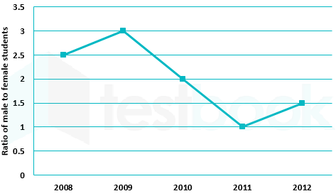
The ratio of male to female students in a college for five years is plotted in the following line graph.

If the number of female students in 2011 and 2012 is equal, what is the ratio of male students in 2012 to male students in 2011?

  1. ((a))

    1 : 1

  2. ((b))

    2 : 1

  3. ((c))

    1.5 : 1

  4. ((d))

    2.5 : 1

Show Answer
Answer: ((c))

1.5 : 1

The number of female students in 2011 and 2012 is equal.

number of males student in 2011 = number of female students in 2011 = x 

In 2012, Male students ÷ Female students = 1.5

Therefore Male students in 2012 = 1.5 ×  Female students = 1.5 × x

In 2012 and 2011, ratio of Male students to Male students = ( 1.5 × x ) ÷  x = 1.5: 1

10

Equation: (7526)8 − (Y)8 = (4364)8, where (X)N stands for X to the base N. Find Y.

  1. ((a))

    1634

  2. ((b))

    1737

  3. ((c))

    3142

  4. ((d))

    3162

Show Answer
Answer: ((c))

3142

Calculation:

(7526)8 − (Y)8 = (4364)8

(7526)8 − (4364)8 = (Y)8

∴ (Y)8 = (83 × 7 + 82 × 5 + 81 × 2 + 80 × 6 ) − (83 × 4 + 82 × 3 + 81 × 6+ 80 × 4)

∴ (Y)8 =  3926 − 2292

∴ (Y)8 =  (1634)10

DivisorDividendRemainder
81634
82042
8254
831
03(↑ )


(Y)8 =  (3926)10 = (3142)8

Electrical Engineering (55 questions)

11

Two matrices A and B are given below:

\(A = \left[ {\begin{array}{{20}{c}} p&q\ r&s \end{array}} \right];;;;;;;B = \left[ {\begin{array}{{20}{c}} {{p^2} + {q^2}}&{pr + qs}\ {pr + qs}&{{r^2} + {s^2}} \end{array}} \right]\)

If the rank of matrix A is N, then the rank of matrix B is

  1. ((a))

    N/2

  2. ((b))

    N – 1

  3. ((c))

    N

  4. ((d))

    2 N

Show Answer
Answer: ((c))

N

Concept:

The order of highest ordered non zero minor is called the rank of a matrix.

Example:

If the square matrix is of order n × n then find the determinant of it if the value is non zero then its rank is n if the value comes out to be zero then find the determinant of  (n - 1) order of all sub-matrix if the value comes out to be non zero of any sub-matrix then the rank is n if the value is zero then the same processes continues further and the order at which value of the determinant is non zero is the rank of a matrix, Use this concept only for order  3 × 3 or lower order for more than 3 × 3 order we use the concept of Echelon form matrix.

Calculation:

The determinant of A is, |A| = ps – qr

Determinant of B is, |B| = (p2 + q2) (r2 + s2) – (pr + qs)2

|B| = (p2s2 + q2r2 – 2pqrs)

|B| = (ps - qr)2

Now, it is clear that |A|2 = |B|

If the rank of A, ρ(A) = 1, that means the determinant of the matrix is zero, and hence the determinant of the matrix also zero. Therefore, the rank of the matrix B is 1

If the rank of A, ρ(A) = 2, that means the determinant of the matrix is non-zero, and hence the determinant of the matrix also non-zero. Therefore, the rank of the matrix B is 2.

Therefore, ρ(B) = ρ(A) = N


Echelon form: 

  • The no of zeros before non-zero elements in a row are less than such no of zeros in the next row.
  • Zero rows ( if any ) must follow non-zero rows.
  • The no of non zero's row is called the rank of the matrix when it is in Echelon form.
12

A particle, starting from origin at t = 0 s, is travelling along x-axis with velocity

v=π2cos(π2t)m/sv = \frac{\pi }{2}\cos \left( {\frac{\pi }{2}t} \right)m/s

At t = 3 s, the difference between the distance covered by the particle and the magnitude of displacement from the origin is _______

13

Let ∇⋅(fv) = x2y + y2z + z2x, where f and v are scalar and vector fields respectively. If v = yi + zj + xk, then v⋅∇f is

  1. ((a))

    x2y + y2z + z2x

  2. ((b))

    2xy + 2yz + 2zx

  3. ((c))

    x + y + z

  4. ((d))

    0

Show Answer
Answer: ((a))

x2y + y2z + z2x

Concept:

By vector identity, if A̅ is differentiable vector function and f is differential scalar function of position (x, y, z) then

∇⋅(fA̅) = (∇f)⋅A̅ + f(∇⋅A)

Calculation:

Given ∇⋅(fv) = x2y + y2z + z2x,

v = yi + zj + xk

From the property of vector field

∇⋅(fv) = v⋅ (∇⋅f) – f(∇⋅ v)

⇒ v⋅(∇f) = ∇⋅(fv) + f(∇⋅v)

v=yx+zy+xz=0\nabla \cdot {\rm{v}} = \frac{{\partial y}}{{\partial x}} + \frac{{\partial z}}{{\partial y}} + \frac{{\partial x}}{{\partial z}} = 0

⇒ f(∇⋅v) = 0

v⋅(∇f) = ∇⋅(fv) - 0

v⋅(∇f) = x2y + y2z + z2x

14

Lifetime of an electric bulb is a random variable with density f(x) = kx2, where x is measured in years. If the minimum and maximum lifetimes of bulb are 1 and 2 years respectively, then the value of k is ______

15

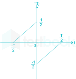
A function f (t) is shown in the figure.

The Fourier transform F(ω) of f(t) is

  1. ((a))

    real and even function of ω

  2. ((b))

    real and odd function of ω

  3. ((c))

    imaginary and odd function of ω

  4. ((d))

    imaginary and even function of ω

Show Answer
Answer: ((c))

imaginary and odd function of ω

Concept:

A function is odd, if the function on one side of t-axisx-axis is sign inverted with respect to the other side or graphically, symmetric about the origin.

f(t) = - f(-t)

Symmetry condition of Fourier Transform

SignalFourier transform
EvenEven
OddOdd
Real & evenReal & even
Imaginary & evenImaginary & even
Imaginary & oddReal & odd
RealReal even & imaginary odd
ImaginaryReal odd & imaginary even
<br>

Calculation:

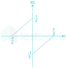
We have the wave form of function f (t) as

From the wave form, f(t) is an odd function

∴ f (t) = - f (- t)

⇒ Fourier transform of the function is imaginary and odd function of ω

16

The line A to neutral voltage is 10∠15°V for a balanced three phase star-connected load with phase sequence ABC. The voltage of line B with respect to line C is given by

  1. ((a))

    10√3 ∠105° V

  2. ((b))

    10∠105° V

  3. ((c))

    10√3 ∠-75° V

  4. ((d))

    -10√3 ∠-90° V

Show Answer
Answer: ((c))

10√3 ∠-75° V

Concept:

Balanced star connected system:

Let's consider phase voltages as VR, VY, and VB. and line voltages as VRY, VYB, and VBR.

And for balanced system magnitudes of all the phase voltages equal and 120° phase displacement between them.

Consider the phasor diagram of a star-connected system (positive sequence) for lagging load.

Figure: Phasor diagram of balanced star connected system (positive sequence) for lagging load.

Properties:

  1. In the balanced star connection the line current and phase current are equal.
  2. Line voltage(VRY) is equal to √3 times of phase voltage VR.
  3. From the phasor diagram, we can observe that line voltage(VRY) leads the phase voltage(VR) by 30°.
  4. The phase displacement between line voltage and line current is (30°+ ϕ) for lagging loads, 30° for resistive loads, and (30°- ϕ) for leading loads.


Calculation:

Line to neutral voltage is nothing but phase voltage of the connection, the relation between line voltage and phase voltage of the balanced star connection is as follows

VL = √3 Vph

Given, Phase voltage Vph = 10∠15°V

VL = √3 × 10∠15°V = 10√3∠15°V

If VA = 10∠0

Then VBC = 10√3 ∠-90

Given VA = 10∠15°

VBC = 10√3 ∠-90 + 15

VBC = 10√3 ∠-75°

Therefore, The voltage of line B with respect to line C is given by 10√3 ∠-75°

17

A hollow metallic sphere of radius r is kept at potential of 1 Volt. The total electric flux coming out of the concentric spherical surface of radius R (> r) is 

  1. ((a))

    4πε0r

  2. ((b))

    4πε0r2

  3. ((c))

    4πε0R

  4. ((d))

    4πε0R2

Show Answer
Answer: ((a))

4πε0r

Concept:

By Gauss law, ϵE.ds=Qenclϵ \oint \vec{E}.d\vec{s}={{Q}_{encl}}

Thus, ϵE.ds=ϵ0E(4πr2)ϵ \oint \vec{E}.d\vec{s}={{ϵ }_{0}}E\left( 4π {{r}^{2}} \right)

ϕ=E.dsϕ = \oint \vec{E}.d\vec{s}

where ϕ = flux coming out of the concentric sphere.

r = radius of the sphere

Calculation:

Since electric potential can be defined as:

V=Q4πϵ0rV = \frac{Q}{{4πϵ{_0}r}}

V = 1 V (given)

The total electric flux coming out of the concentric spherical surface = Charge enclosed Q = 4 π ϵ0 r

18

The driving point impedance Z(s) for the circuit shown below is

  1. ((a))

    s4+3s2+1s3+2s\frac{{{s^4} + 3{s^2} + 1}}{{{s^3} + 2s}}

  2. ((b))

    s4+2s2+4s2+2\frac{{{s^4} + 2{s^2} + 4}}{{{s^2} + 2}}

  3. ((c))

    s2+1s4+s2+1\frac{{{s^2} + 1}}{{{s^4} + {s^2} + 1}}

  4. ((d))

    s3+1s4+s2+1\frac{{{s^3} + 1}}{{{s^4} + {s^2} + 1}}

Show Answer
Answer: ((a))

s4+3s2+1s3+2s\frac{{{s^4} + 3{s^2} + 1}}{{{s^3} + 2s}}

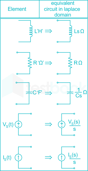
The s-Domain representation of the given circuit 

Z(s)=s+1s[s+1s]1s+(s+1s)Z\left( s \right) = s + \frac{{\frac{1}{s}\left[ {s + \frac{1}{s}} \right]}}{{\frac{1}{s} + \left( {s + \frac{1}{s}} \right)}}

Z(s)=s4+3s2+1s3+2sZ\left( s \right) = \frac{{{s^4} + 3{s^2} + 1}}{{{s^3} + 2s}}

Additional Information

19

A signal is represented by

\(x\left( t \right) = \left{ {\begin{array}{*{20}{c}} 1&{\left| t \right|}&{ < 1}\ 0&{\left| t \right|}&{ > 1} \end{array}} \right.\)

The Fourier transform of the convolved signal y(t) = x(2t) * x(t/2) is

  1. ((a))

    4ω2sin(ω2)sin(2ω)\frac{4}{{{\omega ^2}}}\sin \left( {\frac{\omega }{2}} \right){\rm{sin}}\left( {2\omega } \right)

  2. ((b))

    4ω2sin(ω2)\frac{4}{{{\omega ^2}}}\sin \left( {\frac{\omega }{2}} \right)

  3. ((c))

    4ω2sin(2ω)\frac{4}{{{\omega ^2}}}\sin \left( {2\omega } \right)

  4. ((d))

    4ω2sin2ω\frac{4}{{{\omega ^2}}}{\sin ^2}\omega

Show Answer
Answer: ((a))

4ω2sin(ω2)sin(2ω)\frac{4}{{{\omega ^2}}}\sin \left( {\frac{\omega }{2}} \right){\rm{sin}}\left( {2\omega } \right)

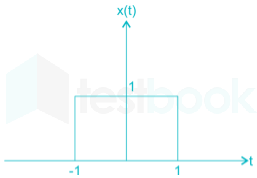
We have, \(x\left( t \right) = \left{ {\begin{array}{*{20}{c}} 1&{\left| t \right|}&{ < 1}\ 0&{\left| t \right|}&{ > 1} \end{array}} \right.\)

Its wave form is given as

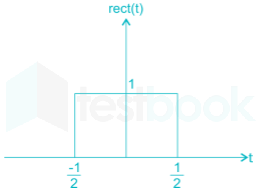
Now, the wave form of rectangular function, rect (t) is

x(t)=rectt2\therefore x\left( t \right) = rect\frac{t}{2}

The Fourier transform pair for rectangular function is

rect(tτ)τsinc(ωτ2π)rect\left( {\frac{t}{\tau }} \right) \leftrightarrow \tau \sin c\left( {\frac{{\omega \tau }}{{2\pi }}} \right)

So, rect(t2)2sinc(ωπ)rect\left( {\frac{t}{2}} \right) \leftrightarrow 2\sin c\left( {\frac{\omega }{\pi }} \right)

Similarly, rect(t4)4sinC(2ωπ)rect\left( {\frac{t}{4}} \right) \leftrightarrow 4\sin C\left( {\frac{{2\omega }}{\pi }} \right)

=4sin(2ω)2ω=2sin(2ω)ω rect(t)sinC(ω2π)=sin(ω2)ω2\begin{array}{l} = \frac{{4{\rm{sin}}\left( {2\omega } \right)}}{{2\omega }} = \frac{{2{\rm{sin}}\left( {2\omega } \right)}}{\omega }\ rect\left( t \right) \leftrightarrow \sin C\left( {\frac{\omega }{{2\pi }}} \right) = \frac{{\sin \left( {\frac{\omega }{2}} \right)}}{{\frac{\omega }{2}}} \end{array}

Now, we have the Fourier transform

\(F\left{ {x\left( {2t} \right)} \right} = F\left{ {rect\left( t \right)} \right} = \frac{{sin\left( {\frac{\omega }{2}} \right)}}{{\frac{\omega }{2}}}\)

And \(F\left{ {x\left( {\frac{t}{2}} \right)} \right} = F\left{ {rect\left( {\frac{t}{4}} \right)} \right}\left( {2\omega } \right)\)

=2sin(2ω)ω= \frac{{2{\rm{sin}}\left( {2\omega } \right)}}{\omega }

We get the Fourier transform of y (t) as

\(\begin{array}{l} F\left{ {y\left( t \right)} \right} = F\left{ {x\left( {2t} \right)*x\left( {\frac{t}{2}} \right)} \right}\ = F\left{ {x\left( {2t} \right)} \right}F\left{ {x\left( {\frac{t}{2}} \right)} \right}\ \frac{{sin\left( {\frac{\omega }{2}} \right)}}{{\frac{\omega }{2}}}\frac{{2\sin \left( {2\omega } \right)}}{\omega }\ = \frac{4}{{{\omega ^2}}}sin\left( {\frac{\omega }{2}} \right)\sin \left( {2\omega } \right) \end{array}\)

20

For the signal f(t) = 3 sin 8πt + 6 sin 12πt + sin 14πt, the minimum sampling frequency (in Hz) satisfying the Nyquist criterion is -----------.

21

In a synchronous machine, hunting is predominantly damped by

  1. ((a))

    mechanical losses in the rotor

  2. ((b))

    iron losses in the rotor

  3. ((c))

    copper losses in the stator

  4. ((d))

    copper losses in the rotor

Show Answer
Answer: ((d))

copper losses in the rotor

In synchronous motors, the phenomenon of successive overshoots and undershoots in the motor speed due to sudden changes in the load is called Hunting. After a sudden change of the load in three-phase synchronous machine, the rotor has to search or hunt for its new equilibrium position. It causes hunting which can be damped by rotor copper losses.

Causes of hunting

  • Periodic variation of load
  • Sudden changes in load
  • Faults occurring in the system when supplied by the generator
  • Sudden change in the field current
  • Cyclic variations of the load torque


Effects of hunting

  • It can lead to loss of synchronism
  • It can cause variations of the supply voltage producing undesirable lamp flicker
  • The possibility of a resonance condition increases. If the frequency of the torque component becomes equal to that of the transient oscillations of the synchronous machine, resonance may take place
  • Large mechanical stresses may develop in the rotor shaft
  • The machine losses increases and the temperature of the machine rises


Reduction of Hunting

  • Use of damper windings
  • Use of flywheels
22

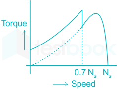
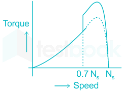
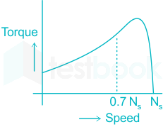
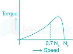
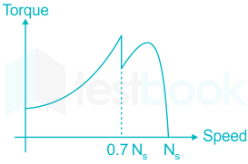
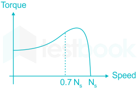
A single phase induction motor is provided with capacitor and centrifugal switch in series with auxiliary winding. The switch is expected to operate at a speed of 0.7 Ns, but due to malfunctioning the switch fails to operate. The torque-speed characteristic of the motor is represented by

  1. ((a))

  2. ((b))

  3. ((c))

  4. ((d))

Show Answer
Answer: ((c))

A 1ϕ IM is having a capacitor and centrifugal switch in series with auxiliary winding. The switch is expected to operate at a speed of 0.7Ns

If the switch operates correctly, then torque-speed characteristic is

But, the switch does not operate due to the malfunctioning.

So there will be no discontinuity in the characteristic curve.

As the capacitor is present permanently, the motor behaves like an unbalanced 2 phase motor.

Thus, we have the modified characteristic curve of the motor as

23

The no-load speed of a 230 V separately excited dc motor is 1400 rpm. The armature resistance drop and the brush drop are neglected. The field current is kept constant at rated value. The torque of the motor in Nm for an armature current of 8 A is _______

24

In a long transmission line with r, l, g and c are the resistance, inductance, shunt conductance and capacitance per unit length, respectively, the condition for distortion less transmission is

  1. ((a))

    rc = lg

  2. ((b))

    r=l/cr = \sqrt {l/c}

  3. ((c))

    rg = lc

  4. ((d))

    g=c/lg = \sqrt {c/l}

Show Answer
Answer: ((a))

rc = lg

For Distortion less Transmission line:

r = Resistance per unit length

l = Inductance per unit length

g = Shunt conductance per unit length

c = Capacitance per unit length

rl=gc\frac{r}{l} = \frac{g}{c}

or rc = lg

Additional Information

Phase constant

β=ωlc\beta = {\rm{\omega }}\sqrt {{\rm{lc}}}

Attenuation constant

α=RC\alpha = \sqrt {RC}

v=ωβ=1lcv = \frac{\omega }{\beta } = \frac{1}{{\sqrt {lc} }}

25

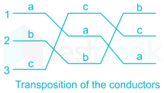
 For a fully transposed transmission line

  1. ((a))

    positive, negative and zero sequence impedances are equal.

  2. ((b))

    positive and negative sequence impedances are equal.

  3. ((c))

    zero and positive sequence impedances are equal.

  4. ((d))

    negative and zero sequence impedances are equal

Show Answer
Answer: ((b))

positive and negative sequence impedances are equal.

Purpose of Transposition:

  • Transmission lines are transposed to prevent interference with neighbouring telephone lines.
  • The transposition arrangement of high voltage lines helps to reduce the system power loss.
  • We have developed transposition system for Single circuit tower using same tension tower with reduced deviation angle.
  • Transposition arrangement of power line helps to reduce the effect of inductive coupling.
  • It is proved more economical Solution, in comparison of the conventional transposition system.
<br>

Important:

Transposition arrangement

The transposition arrangement of the conductor can simply show in the following the figure. The conductor in Position 1, Position 2 and Position 3 changes in a specific arrangement to reduce the effect of capacitance and the electrostatic unbalanced voltages.

Z1 = Z2 = ZS - Zm

Zo = ZS + 2Zm

Where,

Z1 = positive sequence impedance

Z2 = negative sequence impedance

Zm= mutual impedance

ZS= self impedance

Positive and negative sequence impedances are equal.
26

A 183 – bus power system has 150 PQ buses and 32 PV buses. In the general case, to obtain the load flow solution using Newton – Raphson method in polar coordinates, the minimum number of simultaneous equations to be solved is_________.

27

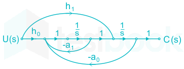
The signal flow graph of a system is shown below. U(s) is the input and C(s) is the output.

Assuming, h1 = b1 and h0 = b0 – b1a1, the input-output transfer function, G(s)=C(s)R(s)G\left( s \right) = \frac{{C\left( s \right)}}{{R\left( s \right)}} of the system is given by

  1. ((a))

    G(s)=b0s+b1s2+a0s+a1G\left( s \right) = \frac{{{b_0}s + {b_1}}}{{{s^2} + {a_0}s + {a_1}}}

  2. ((b))

    G(s)=a1s+a0s2+b1s+b0G\left( s \right) = \frac{{{a_1}s + {a_0}}}{{{s^2} + {b_1}s + {b_0}}}

  3. ((c))

    G(s)=b1s+b0s2+a1s+a0G\left( s \right) = \frac{{{b_1}s + {b_0}}}{{{s^2} + {a_1}s + {a_0}}}

  4. ((d))

    G(s)=a0s+a1s2+b0s+b1G\left( s \right) = \frac{{{a_0}s + {a_1}}}{{{s^2} + {b_0}s + {b_1}}}

Show Answer
Answer: ((c))

G(s)=b1s+b0s2+a1s+a0G\left( s \right) = \frac{{{b_1}s + {b_0}}}{{{s^2} + {a_1}s + {a_0}}}

Concept:

According to Mason’s gain formula, the transfer function is given by

\(TF=\frac{\mathop{\sum }{k-1}^{n}{{M}{k}}{{\Delta }_{k}}}{\Delta }\)

Where,

 n = no of forward paths

Mk = kth forward path gain

Δk = the value of Δ which is not touching the kth forward path

Δ = 1 – (sum of the loop gains) + (sum of the gain product of two non-touching loops) – (sum of the gain product of three non-touching loops)

Application:

Number of forward paths = 2

P1=h0s2,;P2=h1s{P_1} = \frac{{{h_0}}}{{{s^2}}},;{P_2} = \frac{{{h_1}}}{s}

Number of loops = 2

L1=a1s,L2=a0s2{L_1} = - \frac{{{a_1}}}{s},{L_2} = - \frac{{{a_0}}}{{{s^2}}}

Δ=1+a1s+a0s2{\rm{\Delta }} = 1 + \frac{{{a_1}}}{s} + \frac{{{a_0}}}{{{s^2}}}

Δ1=1,;Δ2=1+a1s{{\rm{\Delta }}_1} = 1,;{{\rm{\Delta }}_2} = 1 + \frac{{{a_1}}}{s}

Transfer function =h0s2(1)+h1s(1+a1s)1+a1s+a0s2 = \frac{{\frac{{{h_0}}}{{{s^2}}}\left( 1 \right) + \frac{{{h_1}}}{s}\left( {1 + \frac{{{a_1}}}{s}} \right)}}{{1 + \frac{{{a_1}}}{s} + \frac{{{a_0}}}{{{s^2}}}}}

=h0+h1(s+a1)s2+a1s+a0 = \frac{{{h_0} + {h_1}\left( {s + {a_1}} \right)}}{{{s^2} + {a_1}s + {a_0}}}

=b0b1a1+b1(s+a1)s2+a1s+a0 = \frac{{{b_0} - {b_1}{a_1} + {b_1}\left( {s + {a_1}} \right)}}{{{s^2} + {a_1}s + {a_0}}}

G(s)=b1s+b0s2+a1s+a0G\left( s \right) = \frac{{{b_1}s + {b_0}}}{{{s^2} + {a_1}s + {a_0}}}

28

A single-input single-output feedback system has forward transfer function G(s) and feedback transfer function H(s). It is given that |G(s)H(s)| < 1. Which of the following is true about the stability of the system?

  1. ((a))

    The system is always stable

  2. ((b))

    The system is stable if all zeros of G(s)H(s) are in left half of the s-plane

  3. ((c))

    The system is stable if all poles of G(s)H(s) are in left half of the s-plane

  4. ((d))

    It is not possible to say whether or not the system is stable from the information given

Show Answer
Answer: ((c))

The system is stable if all poles of G(s)H(s) are in left half of the s-plane

Concept:

D(s) = 1 + G(s)H(s)

D(s) gives the roots of characteristic equation i.e. closed-loop poles.

Nyquist stability criteria state that the number of unstable closed-loop poles is equal to the number of unstable open-loop poles plus the number of encirclements of the origin of the Nyquist plot of the complex function D(s).

It can be slightly simplified if instead of plotting the function D(s) = 1 + G(s)H(s), we plot only the function G(s)H(s) around the point and count encirclement of the Nyquist plot of around the point (-1, j0).

From the principal of argument theorem, the number of encirclements about (-1, j0) is

N = P - Z

Where

Where P = Number of open-loop poles on the right half of s plane

Z = Number of closed-loop poles on the right half of s plane

Calculation:

For the given system, we have |G(s)H(s)| < 1

So, we may easily conclude that the Nyquist-plot intersect the negative real axis between 0 and -1 point, i.e. the Nyquist plot does not enclose the point (-1, 0) or in other words number of encirclements is zero.

⇒ N = 0

For a stable closed loop system, we must have Z = 0.

To get Z = 0, from the Nyquist criteria, P must be equal to zero.

Therefore, the system is stable if all poles of G(s)H(s) are in left half of the s-plane.

29

An LPF wattmeter of power factor 0.2 is having three voltage settings 300 V, 150 V, 75 V and two current setting 5 A and 10 A. The full scale reading of the wattmeter is 150 W. If the wattmeter is used with 150 V voltage setting and 10 A current setting, the multiplying factor of the wattmeter is -

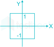
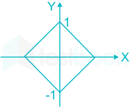
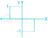
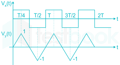
30

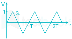
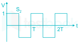
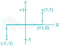
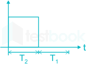
The two signals S1 and S2, shown in figure, are applied to Y and X deflection plates of an oscilloscope.


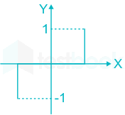
The waveform displayed on the screen is

  1. ((a))

  2. ((b))

  3. ((c))

  4. ((d))

Show Answer
Answer: ((a))

S1 → applied to y → vertical plates

S2 → applied to x → horizontal plates

Observing the waveform, we conclude that

For 0 < t < T/2, 0 < S1 < 1 and S2 = 1

And at t = T/2, S1 = S2 = 0

For T/2 < t < T, 0 > S1 > - 1 and S2 = 1

We can represent this data in tabular form

t(x, y)
0(+1, 0)
T/4(+1, +1)
T/2(+1, 0) and (-1, 0)
3T/4(-1, -1)
T(-1, 0) and (+1, 0)


Thus the waveform displayed on the CRO screen is,

31

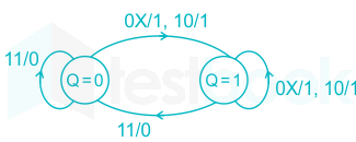
A state diagram of a logic gate which exhibits delay in the output is shown in the figure, where X is the don’t care condition and Q is the output representing the state

The logic gate represented by the state diagram is

  1. ((a))

    XOR gate

  2. ((b))

    OR gate

  3. ((c))

    AND gate

  4. ((d))

    NAND gate

Show Answer
Answer: ((d))

NAND gate

ABYQ
0010
0011
0110
0111
1010
1011
1100
1101

From above truth table, state diagram → NAND Gate.

32

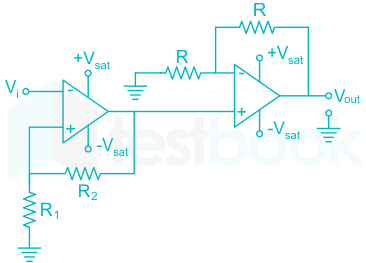
An operational-amplifier circuit is shown in the figure.

The output of the circuit for a given input v1 is

  1. ((a))

    (R2R1)vi- \left( {\frac{{{R_2}}}{{{R_1}}}} \right){v_i}

  2. ((b))

    (1+R2R1)vi- \left( {1 + \frac{{{R_2}}}{{{R_1}}}} \right){v_i}

  3. ((c))

    (1+R2R1)vi\left( {1 + \frac{{{R_2}}}{{{R_1}}}} \right){v_i}

  4. ((d))
    • Vsat or - Vsat
Show Answer
Answer: ((d))
  • Vsat or - Vsat

Concept:

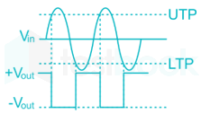
  • Schmitt trigger is basically bistable multivibrator
  • Multivibrator which has both the state stable is called a bistable multivibrator
  • Schmitt trigger is to convert any regular or irregular shaped input waveform into a square wave pulse.

Explanation:

As the positive feedback employed to the first operational amplifier,

(i) If vi > Vsat; then o/p voltage will be Vsat

(ii) If vi < -Vsat , then o/p voltage will be -Vsat

(iii) If -Vsat < vi < Vsat , then o/p voltage varies according to the applied input.

For the given op-Amp circuit, we assume that,

-Vsat < vi < Vsat

Applying KCL at the non-inverting terminal of first op-Amp, we have

vi0R1+vixR2=0\frac{{{v_i} - 0}}{{{R_1}}} + \frac{{{v_i} - x}}{{{R_2}}} = 0

vi(1R1+1R2)=xR2{v_i}\left( {\frac{1}{{{R_1}}} + \frac{1}{{{R_2}}}} \right) = \frac{x}{{{R_2}}}

x=(R1+R2R1)vix = \left( {\frac{{{R_1} + {R_2}}}{{{R_1}}}} \right){v_i}

Where x is the voltage at the non-inverting terminal of 2nd op-Amp.

2nd op-Amp is a non-inverting amplifier so applying KCL, we get

x0R+xV0R=0\frac{{x - 0}}{R} + \frac{{x - {V_0}}}{R} = 0

V0 = 2x

V0=2viR1(R1+R2)=2vi(1+R2R1){V_0} = \frac{{2{v_i}}}{{{R_1}}}\left( {{R_1} + {R_2}} \right) = 2{v_i}\left( {1 + \frac{{{R_2}}}{{{R_1}}}} \right)

Since there is no single output, our assumption is wrong and vi > +Vsat and vi < - Vsat.

As it exceeds the supply voltage range. V0 is +Vsat or - Vsat

33

In 8085A microprocessor, the operation performed by the instruction LHLD 2100H is

  1. ((a))

    (H) ← 21H, (L) ← 00H

  2. ((b))

    (H) ← (2100H), (L) ← M (2101H)

  3. ((c))

    (H) ← M (2101H), (L) ← M (2100H)

  4. ((d))

    (H) ← 00H, (L) ← 21H

Show Answer
Answer: ((c))

(H) ← M (2101H), (L) ← M (2100H)

For the 8085A microprocessor, given instruction is LHLD 2100H

This operation load registers L and H with the content in the memory at location 2100H and 2101H respectively

i.e. (H) ← M (2101H) & (L) ← M (2100H)

where L is lower address data and H is higher address data.

34

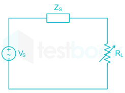
A non-ideal voltage source VS has an internal impedance of ZS If a purely resistive load is to be chosen that maximizes the power transferred to the load, its value must be

  1. ((a))

    0

  2. ((b))

    Real part of Zs

  3. ((c))

    Magnitude of Zs

  4. ((d))

    Complex conjugate of Zs

Show Answer
Answer: ((c))

Magnitude of Zs

Concept:

Maximum power is transferred tom load impedance when load impedance is complex conjugate Source impedance.

\({{\rm{Z}}{\rm{L}}} = {\rm{Z}}{{\rm{th}}}^{\rm{*}}\)

And the maximum power is given by

\({{\rm{P}}{{\rm{max}}}} = \frac{{{\rm{V}}{\rm{s}}^2}}{{4{{\rm{R}}_{\rm{s}}}}}\)

\({\rm{Where;}}{{\rm{R}}{\rm{s}}} = {\rm{Re}}\left[ {{{\rm{Z}}{\rm{s}}}} \right]\)

Special Case:

Here phase balancing is not possible. So at least magnitude must be equal in order to get maximum power transferred through RL.

\( \Rightarrow {{\rm{R}}{\rm{L}}} = \left| {{{\rm{Z}}{\rm{s}}}} \right|\)

35

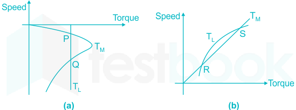
The torque-speed characteristics of motor (TM) and load (TL) for two cases are shown in the figure (a) and (b). The load torque is equal to motor torque at points P, Q, R and S

The stable operating points are

  1. ((a))

    P and R

  2. ((b))

    P and S

  3. ((c))

    Q and R

  4. ((d))

    Q and S

Show Answer
Answer: ((b))

P and S

Concept:

  • When Tm = TL then motor runs at constant speed.
  • When Tm > TL then motor will accelerate & speed will increase.
  • When Tm < TL then motor will retard & speed will decrease.

where, Tm = motor torque & TL = Load Torque

Explanation:

At point 'P'-

If speed slightly increased, then TL > Tm As a result there will be retardation & it will come back to point P

If speed slightly decreased, then TL < Tm As a result, there will be acceleration & it will come back to point P

Therefore operation is STABLE at operating point 'P'.

At point Q - 

If speed is slightly increased, then TL < Tm so, there will be acceleration & the speed will further increase.

If speed is slightly decreased, then TL > Tm then there will be retardation & the speed will decrease further.

Therefore, operation is UNSTABLE at operating point 'Q'.

At point 'R'

If speed slightly increased, then TL > Tm. there will be Acceleration & motor's speed will increase

Therefore, operation is UNSTABLE at point 'R'.

At point 'S'

If speed slightly increased, then TL > Tm, then there will be retardation & motor's speed will decrease. As a result motion will back to original speed. therefore, operation is STABLE at point 'S'.

36

Integration of the complex function f(z)=z2z21f\left( z \right) = \frac{{{z^2}}}{{{z^2} - 1}} in the counterclockwise direction, around |z – 1| = 1, is

  1. ((a))

    -πi

  2. ((b))

    0

  3. ((c))

    πi

  4. ((d))

    2πi

Show Answer
Answer: ((c))

πi

Concept:

Cauchy’s Theorem:

If f(z) is an analytic function and f’(z) is continuous at each point within and on a closed curve C, then

Cf(z)dz=0\mathop \oint \limits_C f\left( z \right)dz = 0

Cauchy’s Integral Formula:

If f(z) is an analytic function within a closed curve and if a is any point within C, then

f(a)=12πiCf(z)zadzf\left( a \right) = \frac{1}{{2\pi i}}\mathop \oint \limits_C \frac{{f\left( z \right)}}{{z - a}}dz

fn(a)=n!2πiCf(z)(za)n+1dz{f^n}\left( a \right) = \frac{{n!}}{{2\pi i}}\mathop \oint \limits_C \frac{{f\left( z \right)}}{{{{\left( {z - a} \right)}^{n + 1}}}}dz

Residue Theorem:

If f(z) is analytic in a closed curve C except at a finite number of singular points within C, then

\(\mathop \smallint \limits_C f\left( z \right)dz = 2\pi i \times \left[ {{\rm{sum;of;residues;at;the;singualr;points;within;C}}} \right]\)

Formula to find residue:

  1. If f(z) has a simple pole at z = a, then

Res;f(a)=limza[(za)f(z)]Res;f\left( a \right) = \mathop {\lim }\limits_{z \to a} \left[ {\left( {z - a} \right)f\left( z \right)} \right]

  1. If f(z) has a pole of order n at z = a, then

\(Res;f\left( a \right) = \frac{1}{{\left( {n - 1} \right)!}}{\left{ {\frac{{{d^{n - 1}}}}{{d{z^{n - 1}}}}\left[ {{{\left( {z - a} \right)}^n}f\left( z \right)} \right]} \right}_{z = a}}\)

Application:

Given function is f(z)=z2z21f\left( z \right) = \frac{{{z^2}}}{{{z^2} - 1}}

Poles: z = 1, -1

|z – 1| = 1

⇒ |x – 1 + iy| = 1

(x1)2+y2=1 \Rightarrow \sqrt {{{\left( {x - 1} \right)}^2} + {y^2}} = 1

The given region is a circle with the centre at (1, 0) and the radius is 1.

Only pole z = 1, lies within the given region.

Residue at z = 1 is, limz1z2(z+1)=0.5\mathop {\lim }\limits_{z \to 1} \frac{{{z^2}}}{{\left( {z + 1} \right)}} = 0.5

The value of the integral = 2πi × 0.5 = πi

37

The mean thickness and variance of silicon steel laminations are 0.2 mm and 0.02 respectively. The varnish insulation is applied on both the sides of the laminations. The mean thickness of one side insulation and its variance are 0.1 mm and 0.01 respectively. If the transformer core is made using 100 such varnish coated laminations, the mean thickness and standard deviation of the core respectively are

  1. ((a))

    30 mm and 0.22

  2. ((b))

    30 mm and 2.44

  3. ((c))

    40 mm and 2.44

  4. ((d))

    40 mm and 0.24

Show Answer
Answer: ((d))

40 mm and 0.24

Concept:

The total thickness of the transformer core made using 100 varnish-coated laminations will be:

total thickness = (2 x thickness of laminations) + (2 x thickness of one side insulation) x number of laminations

= (2 x 0.2 mm) + (2 x 0.1 mm) x 100

= 40 mm

The variance of the thickness of each varnish-coated lamination can be calculated by summing the variances of the lamination and one side insulation and multiplying by 2 (since there are two sides):

variance of one varnish coated lamination = 2 x (variance of lamination + variance of one side insulation)

= 2 x (0.02 + 0.01)

= 0.06

The standard deviation of the thickness of each varnish-coated lamination is the square root of its variance:

standard deviation of one varnish coated lamination = sqrt(0.06) = 0.245

To calculate the mean thickness and standard deviation of the core, we can use the properties of the normal distribution. The mean thickness of the core will be equal to the total thickness of the core, and the standard deviation of the core will be equal to the square root of the sum of the variances of the individual laminations:

mean thickness of core = 40 mm

variance of one varnish coated lamination x number of laminations = 0.06 x 100 = 6

standard deviation of core = sqrt(6) = 2.45 mm

Therefore, the mean thickness and standard deviation of the transformer core are 40 mm and 2.45 mm, respectively.

38

The function f(x) = ex – 1 is to be solved using Newton-Raphson method. If the initial value of x0 is taken as 1.0, then the absolute error observed at 2nd iteration is _______.

39

The Norton’s equivalent source in amperes as seen into the terminals X and Y is _________.

40

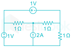
The power delivered by the current source, in the figure, is _______.

41

A perfectly conduction metal plate is placed in x-y plane in a right handed coordinate system. A charge of +32πε0√2 columbs is placed at coordinate (0, 0, 2). ϵ0 is the permittivity of free space. Assume i^,;j^,;k^\hat i,;\hat j,;\hat k  to be unit vectors along x, y and z axes respectively. At the coordinate. (√2, √2, 0), the electric field vector E\vec E (Newtons/Columb) will be

  1. ((a))

    22k^2\sqrt 2 \hat k

  2. ((b))

    2;k^ - 2;\hat k

  3. ((c))

    2;k^2;\hat k

  4. ((d))

    22;k^ - 2\sqrt 2 ;\hat k

Show Answer
Answer: ((b))

2;k^ - 2;\hat k

E=E1+E2=14πε0[Q1R1R13+Q2R2R23]E = {E_1} + {E_2} = \frac{1}{{4\pi {\varepsilon _0}}}\left[ {\frac{{{Q_1}{R_1}}}{{R_1^3}} + \frac{{{Q_2}{R_2}}}{{R_2^3}}} \right]

Q2 = -Q1

R1 = (√2, √2, 0) – (0, 0, 2)

R1 = √2 ax + √2 ay – 2 az  

R2 = (√2, √2, 0) – (0, 0, -2)

= √2 ax + √2 ay – 2 az  

E=14πε0[Q1162(2;ax+2;ay2;az)Q1162(2;ax+2;ay+2;az)]E = \frac{1}{{4\pi {\varepsilon _0}}}\left[ {\frac{{{Q_1}}}{{16\sqrt 2 }}\left( {\sqrt 2 ;{a_x} + \sqrt 2 ;{a_y} - 2;{a_z}} \right) - \frac{{{Q_1}}}{{16\sqrt 2 }}\left( {\sqrt 2 ;{a_x} + \sqrt 2 ;{a_y} + 2;{a_z}} \right)} \right]

=Q162×4πε0[4az]=322πε0162πε0(az) = \frac{Q}{{16\sqrt 2 \times 4\pi {\varepsilon _0}}}\left[ { - 4{a_z}} \right] = \frac{{32\sqrt 2 \pi {\varepsilon _0}}}{{16\sqrt 2 \pi {\varepsilon _0}}}\left( { - {a_z}} \right)

E = -2az

42

A series RLC circuit is observed at two frequencies. At ω1 = 1 k rad/s, we note that source voltage V1 = 100∠0°V results in current I1 = 0.03∠31° A. At ω2 = 2 k rad/s, the source voltage V2 = 100∠0° V results in a current I2 = 2∠0° V A. The closest values for R, L, C out of the following options are

  1. ((a))

    R = 50 Ω ; L = 25 mH ; C = 10 μF

  2. ((b))

    R = 50 Ω ; L = 10 mH ; C = 25 μF

  3. ((c))

    R = 50 Ω ; L = 50 mH ; C = 5 μF

  4. ((d))

    R = 50 Ω ; L = 5 mH ; C = 50 μF

Show Answer
Answer: ((b))

R = 50 Ω ; L = 10 mH ; C = 25 μF

Concept:

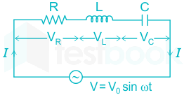
Circuit diagram of series RLC circuit

For a series RLC circuit, the impedance is given by

Z=R2+(XLXC)2Z=\sqrt {{R^2} + {{\left( {{X_L} - {X_C}} \right)}^2}}

Power factor cosϕ=RR2+(XLXC)2\cos \phi = \frac{R}{{\sqrt {{R^2} + {{\left( {{X_L} - {X_C}} \right)}^2}} }} 

Where, 

Inductive reatance XL = ωL = 2πfL

Capacitive reactance XC = 1 / ωC = 1 / 2πfC

Calculation:

Case 1:

V1 = 100∠0° V, I1 = 0.03 ∠31° at ω1 = 1000 r/sec   

Z=V1I1=10000.0331=R+j(XLXC)Z = \frac{{{V_1}}}{{{I_1}}} = \frac{{100\angle 0^\circ }}{{0.03\angle 31^\circ }} = R + j\left( {{X_L} - {X_C}} \right)

ϕ=31=tan1(XLXCR)\phi = 31^\circ = ta{n^{ - 1}}\left( {\frac{{{X_L} - {X_C}}}{R}} \right)

tan31=(XLXCR) ⇒ \tan 31^\circ = \left( {\frac{{{X_L} - {X_C}}}{R}} \right)

tan31=(ω1L1ω1CR) ⇒ \tan 31^\circ = \left( {\frac{{{ω _1}L - \frac{1}{{{ω _1}C}}}}{R}} \right)

[ω1L1ω1C]=0.600×50 ⇒ \left[ {{ω _1}L - \frac{1}{{{ω _1}C}}} \right] = 0.600 \times 50

Substitute the value of ω1 = 1000 r/sec in the above equation

[1000L11000C]=30.04 ⇒ \left[ {{1000 }L - \frac{1}{{{1000}C}}} \right] = 30.04 → 1

Case 2:

V2 = 100∠0° V, I2 = 2∠0° at ω2 = 2000 r/sec

As the phase difference between them is 0° the circuit will be resistive in nature and capacitive reactance will be equal to inductive reactance 

R=V2I2=1002=50;ΩR = \frac{{{V_2}}}{{{I_2}}} = \frac{{100}}{2} = 50;{{\Omega }}

ω2L1ω2C=0{ω _2}L - \frac{1}{{{ω _2}C}} = 0

Substitute the value of ω2 = 2000 r/sec in the above equation

2000L12000C=0{2000}L - \frac{1}{{{2000}C}} = 0

⇒ 4×10⁶×L=1C{4\times10^{6}\times}L = \frac{1}{{C}}

Substitute the above value in equation 1C = 25 μF

[1000L4×106L1000]=30.04 ⇒ \left[ {{1000 }L - \frac{4\times10^{6}L}{{{1000}}}} \right] = 30.04


R = 50 Ω ; L = 10 mH ; C = 25 μF

43

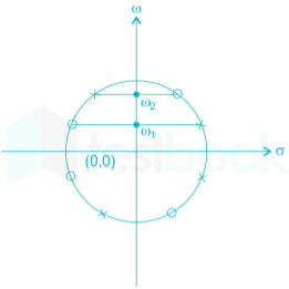
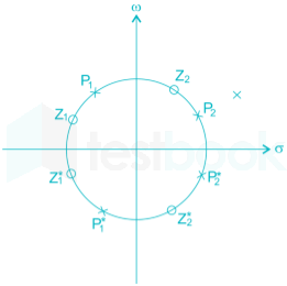
A continuous-time LTI system with system function H(ω) has the following pole-zero plot. For this system, which of the alternatives is TRUE?

  1. ((a))

    |H(0 | > | ω |;| ω |>0

  2. ((b))

    H(ω)| has multiple maxima, at ω1 and ω2

  3. ((c))

    | H(0) | < |H(ω)| ; | ω | > 0

  4. ((d))

    | H(ω) | = constant; -∞ < ω < ∞

Show Answer
Answer: ((d))

| H(ω) | = constant; -∞ < ω < ∞

Pole zero plot is redrawn as

As observed from the given pole-zero plot, poles & zeros are located symmetrically.

Therefore, it is all pass filter.

As we know that, from the property of all pass filter is,

  • |H(jω)| = constant for all values of ω
  • ∠H(jω) = Linearly vary with ω

Hence, the correct option is (4)

44

A sinusoid x(t) of unknown frequency is sampled by an impulse train of period 20 ms. The resulting sample train is next applied to an ideal lowpass filter with cutoff at 25 Hz. The filter output is seen to be a sinusoid of frequency 20 Hz. This means that x(t) is

  1. ((a))

    10 Hz

  2. ((b))

    60 Hz

  3. ((c))

    30 Hz

  4. ((d))

    90 Hz

Show Answer
Answer: ((c))

30 Hz

Period of sampling train, Ts = 20 ms

fs=120×103=50Hz\therefore {f_s} = \frac{1}{{20 \times {{10}^{ - 3}}}} = 50{\rm{Hz}}

If frequency of x(t) is fx, then after sampling the signal, the sampled signal has the frequency,

fs - fx = 50 - fx and fs + fx = 50 + fs

 Now, the sampled signal is applied to and ideal low pass filter with cut off frequency.

fc = 25 Hz

Now, the o/p of filter carried a single frequency component of 20 Hz

∴, only (fsfx)\left( {{f_s} - {f_x}} \right) component passes through the filter, ie.

fs - fx < 25

and fs - fx = 20

50 - f = 20

fx = 50 - 20 = 30 Hz

45

A different non constant even function x(t) has a derivative y(t), and their respective Fourier Transforms are X(ω) and Y(ω). Which of the following statements is TRUE

  1. ((a))

    X(ω) and Y(ω) are both real

  2. ((b))

    X(ω) is real and Y(ω) is imaginary

  3. ((c))

    X(ω) and Y(ω) are both imaginary

  4. ((d))

    X(ω) is imaginary and Y(ω) is real

Show Answer
Answer: ((b))

X(ω) is real and Y(ω) is imaginary

We have,

              y(t)=dx(t)dty\left( t \right) = \frac{{dx\left( t \right)}}{{dt}}........eq(i)

Since, x(t) is a Differentiable non - constant even function.

so, x(t) = x(-t) and its Fourier transform X(ω) = X(-ω)

Taking Fourier transform of eq(i)

⇒ Y(ω) = jω X(ω)

Y(-ω) = j(-ω)X(-ω)

Y(-ω) = -jω X(ω)

Y(-ω) = -Y(ω) 

So, Y(ω) is odd and imaginary.

Since, x(t) is differentiable, non-constant,  even function. So, its frequency response will be real i.e., X(ω) is real.

Hence, the correct option is (2)

46

An open circuit test is performed on 50 Hz transformer, using variable frequency source and keeping V/f ratio constant, to separate its eddy current and hysteresis losses. The variation of core loss/frequency as function of frequency is shown in the figure

The hysteresis and eddy current losses of the transformer at 25 Hz respectively are

  1. ((a))

    250 W and 2.5 W

  2. ((b))

    250 W and 62.5 W

  3. ((c))

    312.5 W and 62.5 W

  4. ((d))

    312.5 W and 250 W

Show Answer
Answer: ((b))

250 W and 62.5 W

Concept:

At constant V/f ratio, the total core losses of the transformer are,

PC = PH f + Pe f2

Where,

f = frequency

PH = Hysteresis losses constant

Pe = eddy current losses constant

Calculation:

Pcf=PH+Pef\frac{{{P_c}}}{f} = {P_H} + {P_e}f 

i.e. the plot between Pcf\frac{{{P_c}}}{f} and f is a straight line.

From the graph we have value of PH = 10

& Pe=(PcfPH)f=151050=110{P_e} = \frac{{\left( {\frac{{{P_c}}}{f} - {P_H}} \right)}}{f} = \frac{{15 - 10}}{{50}} = \frac{1}{{10}} 

Hence, we get PH × f = 10 × 25 = 250 W

Pe × f2 =110×(25)2=62.5;W= \frac{1}{{10}} \times {\left( {25} \right)^2} = 62.5;W

47

A non-salient pole synchronous generator having synchronous reactance of 0.8 pu is supplying 1 pu power to a unity power factor load at a terminal voltage of 1.1 pu. Neglecting the armature resistance, the angle of the voltage behind the synchronous reactance with respect to the angle of the terminal voltage in degrees is _______

48

A separately excited 300 V DC shunt motor under no load runs at 900 rpm drawing an armature current of 2 A. The armature resistance is 0.5 Ω and leakage inductance is 0.01 H. When loaded, the armature current is 15 A. Then the speed in rpm is______ 

49

The load shown in the figure absorbs 4 kW at a power factor of 0.89 lagging.

Assuming the transformer to be ideal, the value of the reactance X to improve the input power factor to unity is _________

50

The parameters measured for a 220V/110V, 50 Hz, single-phase transformer are:

Self inductance of primary winding = 45 mH

Self inductance of secondary winding = 30 mH

Mutual inductance between primary and secondary windings = 20 mH

Using the above parameters, the leakage (Ll1, Ll2) and magnetizing (Lm) inductances at referred to primary side in the equivalent circuit respectively, are

  1. ((a))

    5 mH, 20 mH and 40 mH

  2. ((b))

    5 mH, 80 mH and 40 mH

  3. ((c))

    25 mH, 10 mH and 20 mH

  4. ((d))

    45 mH, 30 mH and 20 mH

Show Answer
Answer: ((b))

5 mH, 80 mH and 40 mH

Concept:

The leakage inductance is defined as the ratio of no of turns multiplied by leakage flux divided by current through it.

The magnetizing inductance is the difference of self-inductance of the primary winding and primary leakage inductance

Let N1 = primary turns,

N2 = secondary turns

Let a current I1, flowing through the primary produce a flux ϕ1, of which part ϕ links with the secondary also while remaining (ϕ1 – ϕ) is the leakage flux.

Self-inductance of primary L1=N1ϕ1I1{L_1} = \frac{{{N_1}{\phi _1}}}{{{I_1}}}

And mutual inductance between primary and secondary, M=N2ϕI1M = \frac{{{N_2}\phi }}{{{I_1}}}

The leakage inductance of the primary

Ll1=N1(ϕ1ϕ)I1=N1ϕ1I1N1ϕI1{L_{l1}} = \frac{{{N_1}\left( {{\phi _1} - \phi } \right)}}{{{I_1}}} = \frac{{{N_1}{\phi _1}}}{{{I_1}}} - \frac{{{N_1}\phi }}{{{I_1}}} 

=L1((N2ϕ)2)(N1N2) = {L_1} - \left( {\frac{{\left( {{N_2}\phi } \right)}}{2}} \right)\left( {\frac{{{N_1}}}{{{N_2}}}} \right) 

Ll1=L1(N1N2)M{L_{l1}} = {L_1} - \left( {\frac{{{N_1}}}{{{N_2}}}} \right)M

Similarly,

Ll2=L2(N2N1)M{L_{l2}} = {L_2} - \left( {\frac{{{N_2}}}{{{N_1}}}} \right)M

Calculation:

L1 = 45 mH, L2 = 30 mH, M = 20 mH

Ll1 = 40 – 2(20) = 5 mH

Ll2 = 30 – 0.5 (20) = 20mH

Leakage inductance of secondary referred to primary = 4Ll2 = 80 mH

And the magnetizing inductance Lm (referred to primary) = L1 – Ll1 = 45 mH – 5 mH = 40 mH

51

For a 400 km long transmission line, the series impedance is (0.0 + j 0.5) Ω / km and the shunt admittance is (0.0 + j 5.0) μmho/km. The magnitude of the series impedance (in Ω) of the equivalent π circuit of the transmission line is_________.

52

The complex power consumed by a constant – voltage load is given by (P1 + jQ1), Where, 1 kW ≤ P1 ≤ 1.5 kW and 0.5 kVAR ≤ Q1 ≤ 1 kVAR.

A compensating shunt capacitor is chosen such that |Q| ≤ 0.25 kVAR, where Q is the net reactive power consumed by the capacitor – load combination. The reactive power (in kVAR) supplied by the capacitor is__________.

53

The figure shows the single line diagram of a single machine infinite bus system.

The inertia constant of the synchronous generator H = 5 MW –s / MVA. Frequency is 50 Hz. Mechanical power is 1 pu. The system is operating at the stable equilibrium point with rotor angle δ equal to 30°.  A three phase short circuit fault occurs at a certain location on one of the circuits of the double circuit transmission line. During fault, electrical power in pu is Pmax

sin δ. If the values of δ and dδ / dt at the instant of fault clearing are 45° and 3.762 radian/s respectively, then Pmax (in pu) is___________.

54

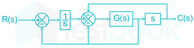
The block diagram of a system is shown in the figure.

If the desired transfer function of the system is

C(s)R(s)=ss2+s+2\frac{{C\left( s \right)}}{{R\left( s \right)}} = \frac{s}{{{s^2} + s + 2}}

then G(s) is

  1. ((a))

    1

  2. ((b))

    s

  3. ((c))

    1/s

  4. ((d))

    ss3+s2s2\frac{{ - s}}{{{s^3} + {s^2} - s - 2}}

Show Answer
Answer: ((b))

s

Concept:

According to Mason’s gain formula, the transfer function is given by

\(TF=\frac{\mathop{\sum }{k-1}^{n}{{M}{k}}{{\Delta }_{k}}}{\Delta }\)

Where,

 n = no of forward paths

Mk = kth forward path gain

Δk = the value of Δ which is not touching the kth forward path

Δ = 1 – (sum of the loop gains) + (sum of the gain product of two non-touching loops) – (sum of the gain product of three non-touching loops)

Application:

Number of forward paths = 1

P1 = G(s)

Number of loops = 3

L1=G(s)s,;L2=G(s),;L3=sG(S){L_1} = - \frac{{G\left( s \right)}}{s},;{L_2} = - G\left( s \right),;{L_3} = - sG\left( S \right)

Δ=1+G(s)s+G(s)+sG(s){\rm{\Delta }} = 1 + \frac{{G\left( s \right)}}{s} + G\left( s \right) + sG\left( s \right)

=1+G(s)[1s+1+s] = 1 + G\left( s \right)\left[ {\frac{1}{s} + 1 + s} \right]

Δ = 1

Transfer function C(s)R(s)=G(s)1+G(s)[1s+1+s]\frac{{C\left( s \right)}}{{R\left( s \right)}} = \frac{{G\left( s \right)}}{{1 + G\left( s \right)\left[ {\frac{1}{s} + 1 + s} \right]}}

It is given that, C(s)R(s)=ss2+s+2\frac{{C\left( s \right)}}{{R\left( s \right)}} = \frac{s}{{{s^2} + s + 2}}

G(s)1+G(s)[1s+1+s]=ss2+s+2 \Rightarrow \frac{{G\left( s \right)}}{{1 + G\left( s \right)\left[ {\frac{1}{s} + 1 + s} \right]}} = \frac{s}{{{s^2} + s + 2}}

G(s)[s2+s+2]=s+G(s)[1+s+s2] \Rightarrow G\left( s \right)\left[ {{s^2} + s + 2} \right] = s + G\left( s \right)\left[ {1 + s + {s^2}} \right]

⇒ G(s) = s

55

Consider the system described by following state space equations

\(\left[ {\begin{array}{{20}{c}} {{{\dot x}_1}}\ {{{\dot x}_2}} \end{array}} \right] = \left[ {\begin{array}{{20}{c}} 0&1\ { - 1}&{ - 1} \end{array}} \right]\left[ {\begin{array}{{20}{c}} {{x_1}}\ {{x_2}} \end{array}} \right] + \left[ {\begin{array}{{20}{c}} 0\ 1 \end{array}} \right]u;y = \left[ {\begin{array}{{20}{c}} 1&0 \end{array}} \right]\left[ {\begin{array}{{20}{c}} {{x_1}}\ {{x_2}} \end{array}} \right]\)

If u is unit step input, then the steady state error of the system is

  1. ((a))

    0

  2. ((b))

    1/2

  3. ((c))

    2/3

  4. ((d))

    1

Show Answer
Answer: ((a))

0

Concept:

The transfer function from the state space representation is given by:

G(s) = C(SI – A)-1 B + D

KP = position error constant = lims0G(s)H(s)\mathop {\lim }\limits_{s \to 0} G\left( s \right)H\left( s \right)

Kv = velocity error constant = lims0sG(s)H(s)\mathop {\lim }\limits_{s \to 0} sG\left( s \right)H\left( s \right)

Ka = acceleration error constant = lims0s2G(s)H(s)\mathop {\lim }\limits_{s \to 0} {s^2}G\left( s \right)H\left( s \right)

Steady state error for different inputs is given by

InputType -0Type - 1Type -2
Unit step11+Kp\frac{1}{{1 + {K_p}}}00
Unit ramp1Kv\frac{1}{{{K_v}}}0
Unit parabolic1Ka\frac{1}{{{K_a}}}


From the above table, it is clear that for type – 1 system, a system shows zero steady-state error for step-input, finite steady-state error for Ramp-input and \infty  steady-state error for parabolic-input.

Calculation:

From the given state-space representation,

\(A = \left[ {\begin{array}{{20}{c}} 0&1\ { - 1}&{ - 1} \end{array}} \right],B = \left[ {\begin{array}{{20}{c}} 0\ 1 \end{array}} \right],C = \left[ {\begin{array}{*{20}{c}} 1&0 \end{array}} \right]\)

\(\left[ {sI - A} \right] = \left[ {\begin{array}{{20}{c}} s&0\ 0&s \end{array}} \right] - \left[ {\begin{array}{{20}{c}} 0&1\ { - 1}&{ - 1} \end{array}} \right] = \left[ {\begin{array}{*{20}{c}} s&{ - 1}\ 1&{s + 1} \end{array}} \right]\)

\({\left[ {sI - A} \right]^{ - 1}} = \frac{1}{{{s^2} + s + 1}}\left[ {\begin{array}{*{20}{c}} {s + 1}&1\ { - 1}&s \end{array}} \right]\)

Transfer function \( = \left[ {\begin{array}{{20}{c}} 1&0 \end{array}} \right]\frac{1}{{{s^2} + s + 1}}\left[ {\begin{array}{{20}{c}} {s + 1}&1\ { - 1}&s \end{array}} \right]\left[ {\begin{array}{*{20}{c}} 0\ 1 \end{array}} \right]\)

=1s2+s+1 = \frac{1}{{{s^2} + s + 1}}

Open-loop transfer function =1s2+s+111s2+s+1 = \frac{{\frac{1}{{{s^2} + s + 1}}}}{{1 - \frac{1}{{{s^2} + s + 1}}}}

=1s(s+1) = \frac{1}{{s\left( {s + 1} \right)}}

It is a type 1 system. The steady-state error for a step input is zero.

56

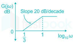
The magnitude Bode plot of a network is shown in the figure.

The maximum phase angle ϕm and the corresponding gain Gm respectively, are

  1. ((a))

    -30° and 1.73 dB

  2. ((b))

    -30° and 4.77 dB

  3. ((c))

    +30° and 4.77 dB

  4. ((d))

    +30° and 1.73 dB

Show Answer
Answer: ((c))

+30° and 4.77 dB

Concept:

Bode plot transfer function is represented in standard time constant form as T(s)=k(sωc1+1)(sωc2+1)(sωc3+1)T\left( s \right) = \dfrac{{k\left( {\dfrac{s}{{{\omega _{{c_1}}}}} + 1} \right) \ldots }}{{\left( {\dfrac{s}{{{\omega _{{c_2}}}}} + 1} \right)\left( {\dfrac{s}{{{\omega _{{c_3}}}}} + 1} \right) \ldots }}

ωc1,ωc2,{\omega _{{c_1}}},{\omega _{{c_2}}},… are corner frequencies.

In a Bode magnitude plot,

  • For a pole at the origin, the initial slope is -20 dB/decade
  • For a zero at the origin, the initial slope is 20 dB/decade
  • The slope of magnitude plot changes at each corner frequency
  • The corner frequency associated with poles causes a slope of -20 dB/decade
  • The corner frequency associated with poles causes a slope of -20 dB/decade
  • The final slope of Bode magnitude plot = (Z – P) × 20 dB/decade
<br>

Where Z is the number zeros and P is the number of poles

Application:

From the given Bode plot,

The corner frequencies are: 1/3 and 1

There is a slope change of +20 dB/decade at ω = 1/3 and hence it is a zero.

There is a slope change of -20 dB/decade at ω = 1 and hence it is a pole.

At low frequencies, 20 log k = 0 dB

⇒ k = 1

Now, the transfer function is G(s)=1+3s1+sG\left( s \right) = \frac{{1 + 3s}}{{1 + s}}

Now it is in the form of 1+asT1+sT\frac{{1 + asT}}{{1 + sT}}

By comparing both the transformers, we get a = 3, T = 1

It is a lead compensator.

The maximum phase =sin1(a1a+1)=sin1(313+1)=30 = {\sin ^{ - 1}}\left( {\frac{{a - 1}}{{a + 1}}} \right) = {\sin ^{ - 1}}\left( {\frac{{3 - 1}}{{3 + 1}}} \right) = 30^\circ

The maximum phase occurs at ω=1Ta=13\omega = \frac{1}{{T\sqrt a }} = \frac{1}{{\sqrt 3 }}

The gain of the transfer function G(s) is Gm=1+9ω21+ω2{G_m} = \frac{{\sqrt {1 + 9{\omega ^2}} }}{{\sqrt {1 + {\omega ^2}} }}

At ω=13\omega = \frac{1}{{\sqrt 3 }}Gm=1+9(13)21+(13)2=3{G_m} = \frac{{\sqrt {1 + 9{{\left( {\frac{1}{{\sqrt 3 }}} \right)}^2}} }}{{\sqrt {1 + {{\left( {\frac{1}{{\sqrt 3 }}} \right)}^2}} }} = \sqrt 3

The gain DB is = 20 log √3 = 4.77 dB

57

A periodic waveform observed across a load is represented by

\(V\left( t \right) = \left{ {\begin{array}{*{20}{c}} {1 + \sin \omega t,;;0 \le \omega t < 6\pi }\ { - 1 + \sin \omega t,;;6\pi \le \omega t < 12\pi } \end{array}} \right.\)

The measured value, using moving iron voltmeter connected across the load, is

  1. ((a))

    32\sqrt {\frac{3}{2}}

  2. ((b))

    23\sqrt {\frac{2}{3}}

  3. ((c))

    32\frac{3}{2}

  4. ((d))

    23\frac{2}{3}

Show Answer
Answer: ((a))

32\sqrt {\frac{3}{2}}

Concept:

Moving iron voltmeter measures the RMS value of the measured voltage.

RMS value of a periodic waveform is \( = \sqrt {\frac{1}{T}\mathop \smallint \limits_0^T {{\left[ {V\left( t \right)} \right]}^2}dt} \)

Calculation:

The given periodic waveform is

\(V\left( t \right) = \left{ {\begin{array}{*{20}{c}} {1 + \sin \omega t,;;0 \le \omega t < 6\pi }\ { - 1 + \sin \omega t,;;6\pi \le \omega t < 12\pi } \end{array}} \right.\)

\(\frac{1}{T}\mathop \smallint \limits_0^T {\left[ {V\left( t \right)} \right]^2}dt\)

\( = \frac{1}{{12\pi }}\left[ {\mathop \smallint \limits_0^{6\pi } {{\left[ {1 + \sin \omega t} \right]}^2}dt + \mathop \smallint \limits_{6\pi }^{12\pi } {{\left[ { - 1 + \sin \omega t} \right]}^2}dt} \right]\)

\( = \frac{1}{{12\pi }}\left[ {\mathop \smallint \limits_0^{6\pi } \left[ {1 + 2\sin \omega t + {{\sin }^2}\omega t} \right]dt + \mathop \smallint \limits_{6\pi }^{12\pi } \left[ {1 - 2\sin \omega t + {{\sin }^2}\omega t} \right]dt} \right]\)

\( = \frac{1}{{12\pi }}\left[ {6\pi + 6\pi + \mathop \smallint \limits_0^{6\pi } \left[ {\frac{{1 - \cos 2\omega t}}{2}} \right]dt + \mathop \smallint \limits_{6\pi }^{12\pi } \left[ {\frac{{1 - \cos 2\omega t}}{2}} \right]dt} \right]\)

=112π[12π+6π]=32 = \frac{1}{{12\pi }}\left[ {12\pi + 6\pi } \right] = \frac{3}{2}

RMS value =32 = \sqrt {\frac{3}{2}}

58

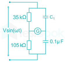
n the bridge circuit shown, the capacitors are loss free. At balance the value of capacitance C1 in microfarad is –

59

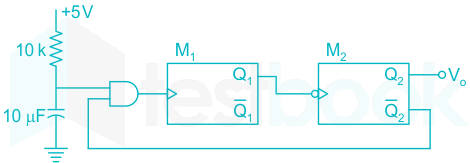
Two monoshot multivibrators, are positive edge triggered (M1) and another negative edge triggered (M2), are connected as shown in figure

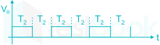
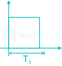
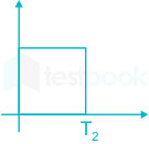
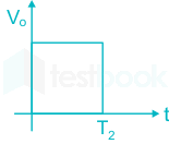
The monoshots M1 and M2 when triggered produce pulses of width T1 and T2 respectively, where T1 > T2. The steady state output voltage v0 of the circuit is

  1. ((a))

  2. ((b))

  3. ((c))

  4. ((d))

Show Answer
Answer: ((c))

  • Mono shot multivibrators are used to generate a single output pulse of a specified width, either ‘HIGH’ or ‘LOW’, when a suitable external trigger signal or pulse T is applied.
  • Trigger signal initiates a timing cycle which causes the output of the monostable to change its state at the start of the timing cycle and will remain in this second state.


When monoshot multivibrator M1 is triggered, it produces a pulse of T1 duration.

Similarly, when monoshot multivibrator M2 is triggered, it produces a pulse of T2 duration.

Let, the output Q2 is initially high, so the output v0 will be high for a time period T2

<sub>

</sub>


Now for this period, Q̅2 = 0, so the output of AND gate is low.

For M1 is positive triggered, M1 will be OFF for duration T2.

After T2 time, Q2 = 0 and Q̅2 = 1

Hence the output of AND gate is 1 i.e. M1 is triggered and the output Q1 is high for duration T1.

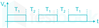
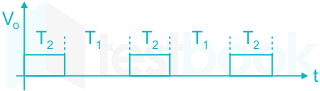
For M2 is negative edge triggered, M2 will be off for the duration T1 and hence, output v0 will be as

After T1 time the output Q1 becomes low, and M2 gets ON due to negative edge triggering. Hence the cycle continues as given below.

60

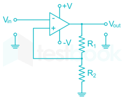
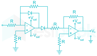
The transfer characteristic of the op – amp circuit shown in figure is

  1. ((a))

  2. ((b))

  3. ((c))

  4. ((d))

Show Answer
Answer: ((c))

Concept:

Precision rectifier:


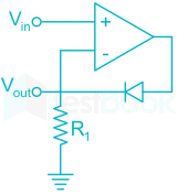
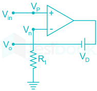
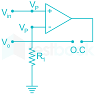
A half-wave precision rectifier is implemented using an op-amp and includes the diode in the feedback loop. This effectively cancels the forward voltage drop of the diode (Vd), so very low signals can still be rectified with minimal error.

The characteristics are shown below.


The Analysis of the given circuit can be done by considering the following two cases:

Case I: [Vin > 0]

When, Vin > 0, the Op-Amp tries to keep Vout = Vn = Vp = Vin and it does so because the forward-biased diode provides the closed-loop feedback path.

Case II: [Vin < 0]

The diode is reverse biased and the op-amp is working in the open-loop as shown in the above figure.

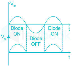
The input and output waveform are as shown in the figure:

Hence the circuit is a precision half-wave rectifier

Important points:

The other types of the precision rectifier and their characteristics are given below.


Explanation:

Case – I : when Vi > 0

In this case, the diode conducts.

Since, the voltage at negative and positive terminals are same for ideal op – amp. So, for the first op – amp, we have

V1=V1+=0V_1^ - = V_1^ + = 0

∴ the o/p of first op – amp is zero, which is applied to negative terminal of second op – amp.

Thus we get the o/p Vo = 0.

Case  - II : When Vi < 0

For this case, the diode is open and the o/p of first op – amp is

∴ the o/p of first op – amp is zero, which is applied to negative terminal of second op – amp.

Thus we get the o/p Vo = 0.

Case  - II : When Vi < 0

For this case, the diode is open and the o/p of first op – amp is

Vo1=RRVi=Vi{V_{{o_1}}} = \frac{{ - R}}{R}{V_i} = - {V_i}

∴ the o/p of second op – amp is

\(\begin{array}{l} {V_o} = \frac{{ - R}}{R}{V_{01}} = {V_i}\ \therefore {V_o} = \left{ {\begin{array}{{20}{c}} {\begin{array}{{20}{c}} 0&{{V_i} > 0} \end{array}}\ {\begin{array}{*{20}{c}} {{V_i}}&{{V_i} < 0} \end{array}} \end{array}} \right. \end{array}\)

61

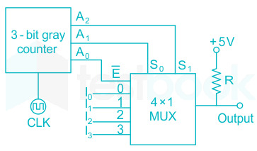
A 3-bit gray counter is used to control the output of the multiplexer as shown in the figure (A2 is MSB and A0 is LSB). The initial state of the counter is 0002. The output is pulled high. The output of the circuit follows the sequence

  1. ((a))

    I0, 1, 1, I1, I3, 1, 1, I2

  2. ((b))

    I0, 1, I1, 1, I2, 1, I3, 1

  3. ((c))

    1, I0, 1, I1, I2, 1, I3, 1

  4. ((d))

    I0, I1, I2, I3, I0, I1, I2, I3

Show Answer
Answer: ((a))

I0, 1, 1, I1, I3, 1, 1, I2

In the given circuit, the 3-bit gray counter converts the given decimal number into gray code.

The output of gray code is connected to the selection lines of the multiplexer.

The output of the multiplexer is pulled high. Therefore, the output is one when the multiplexer is not enabled i.e. when E̅ = 1.

When multiplexer is enabled i.e. E̅ = 0, the multiplexer gives the output according to the selection lines (S1S0).

DecimalBinaryGray code (A2A1A0)S1S0Output of MUX
0000000000I0
10010010011
20100110111
3011010010I1
4100110110I3
51011111111
61101011011
7111100100I2
62

A hysteresis type TTL inverter is used to realize an oscillator in the circuit shown in the figure.

If the lower and upper trigger level voltages are 0.9 V and 1.7 V, the period (in ms), for which output is LOW, is ______

63

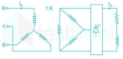
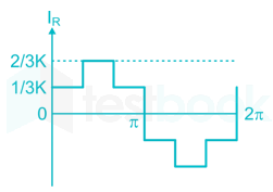
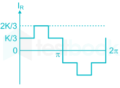
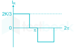
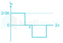
A 3-ϕ fully controlled converter is fed through the star-delta transformer as shown in the figure

The converter is operated at a firing angle of 300. Assuming the load current (Io) to be virtually constant at 1 p.u. and the transformer to be an ideal one, the input phase current waveform is

  1. ((a))

  2. ((b))

  3. ((c))

  4. ((d))

Show Answer
Answer: ((b))

Assuming each secondary winding is identical and has the same resistance R

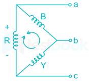
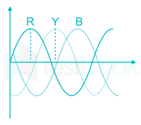
When the R phase has a maximum voltage, lines a and c will conduct. At this condition, the current will be divided into R and YB winding.

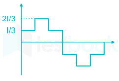
Current through R=I0×2R3R=2I03R = \frac{{{I_0} \times 2R}}{{3R}} = \frac{{2{I_0}}}{3}

Current through B and Y = I03\frac{{{I_0}}}{3}

And I0=2I3{I_0} = \frac{{2I}}{3}

Current through R and Y =I03 = \frac{{{I_0}}}{3}

Current through B =2I03 = \frac{{2{I_0}}}{3}

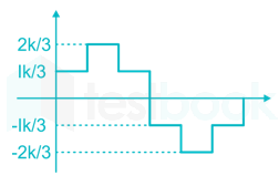
The current through Δ-phase winding

Current through primary Ip=kIs{I_p} = k{I_s}

64

A diode circuit feeds an ideal inductor as shown in the figure. Given VS = 100 sin (ωt), where ω = 100 π rad / s and L = 31.83 mH. The initial value of inductor current is zero. Switch s is closed at t = 2.5 mS. The peak value of inductor current iL(in A) in the first cycle is (in A)

65

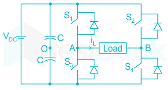
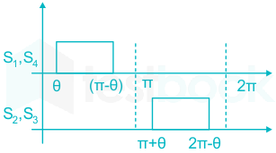
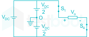
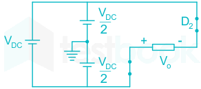
A single-phase voltage source inverter shown in figure is feeding power to a load. The triggering pulses of the devices are also shown in the figure.


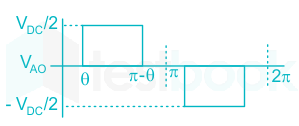
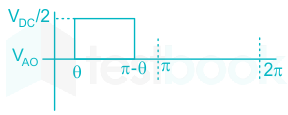
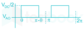
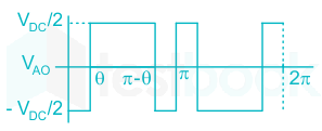
If the load current is sinusoidal and is zero at 0, π, 2π…, the node voltage VAO has the waveform

  1. ((a))

  2. ((b))

  3. ((c))

  4. ((d))

Show Answer
Answer: ((d))

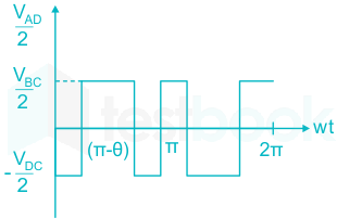
It is given that load current is sinusoidal, so the current conduction is continuous & hence, it is zero at 0, π, 2π,...........

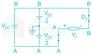
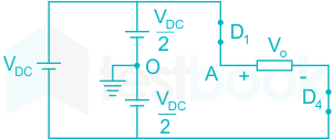
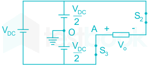
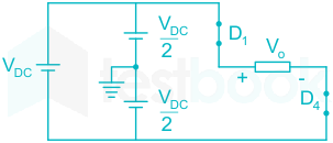
For 0 to θ : S1 is OFF, D3 & D2 is ON

VAo=VDC2V_{Ao} = - \frac{V_{DC}}{2}

For 0 to π - θ :

S1 S4 : ON

VAO=VDC2\rm V_{AO} = \frac{V_{DC}}{2}

For π - θ to θ :

D2D3 : ON

VAO=VDC2\rm V_{AO} = \frac{-V_{DC}}{2}

For π to π + θ :

D1D4 : ON

VAO=VDC2\rm V_{AO} = \frac{V_{DC}}{2}

For π + θ to 2π - θ :

S2S3 : ON

VAO=VDC2\rm V_{AO} =- \frac{V_{DC}}{2}

For 2π - θ to 2π

D1D4 : ON

VAO=VDC2\rm V_{AO} = \frac{V_{DC}}{2}

Hence, the load voltage waveform of VAO is,

Attempt this paper under real exam conditions

Timed interface, section switching, instant scoring, and question-by-question analytics — free.

Start Timed Attempt