Official Paper

GATE EC 2012 Official Paper (Previous Year Paper)

65 questions · 180 minutes · with answers · free

General Aptitude (10 questions)

1

If (1.001)1259 = 3.52 and (1.001)2062 = 7.85, then (1.001)3321 =

  1. ((a))

    2.23

  2. ((b))

    4.33

  3. ((c))

    11.37

  4. ((d))

    27.64

Show Answer
Answer: ((d))

27.64

Given:

(1.001)1259 = 3.52 and (1.001)2062 = 7.85

Concept used:

X(a + b) = X(a) × X(b)

Calculation:

⇒ (1.001)3321 = (1.001)1259 + 2062 

= (1.001)1259 × (1.001)2062

= 3.52 × 7.85

= 27.64

Hence, the correct answer is "27.64".

2

Choose the most appropriate alternative from the options given below to complete the following sentence:

If the tired soldier wanted to lie down, he _______ the mattress out on the balcony.

  1. ((a))

    should take

  2. ((b))

    shall take

  3. ((c))

    should have taken

  4. ((d))

    will have taken

Show Answer
Answer: ((c))

should have taken

The correct answer is 'should have taken'.

Key Points

  • Mixed Conditional Sentence: Mixed conditionals are conditional sentences that mix two different times in one sentence or we can say that the if-clause is not the same as the time in the result.
  • Structure for Mixed conditional (for present condition, past result):
  • If/when + past simple, would have + verb infinitive.
  • Example: 
  • If Sam spoke Russian, he would have translated the letter for you.
  • (But Sam doesn't speak Russian and that is why he didn't translate the letter.)
  • Note: Would can be replaced with should/might in the sentence.

Therefore, the correct sentence is: If the tired soldier wanted to lie down, he should have taken the mattress out on the balcony. 

Additional Information

  • Conditional sentence:- As the name suggests, these sentences express conditions.
  • In conditional sentences, there are two clauses of the sentences. One is a conditional clause and another one is main clause.
  • Other Conditional sentences are-
Types of Conditional SentencesDefinition and examples
Zero conditional SentenceIt expresses a factual condition.
Structure: If/When+ present simple+ present simple
Example: If you put ice in milk, It melts
First Conditional SentenceIt expresses possible and likely future outcomes.
Structure: If/when+present simple, will+ verb infinitive.
Example: If it's hot tomorrow, I'll go for a swim
Second Conditional SentenceIt expresses an Imagination.
Structure: If/when + past simple, would + verb infinitive.
Example: If I finished work earlier, I would leave.
Third Conditional sentenceIt expresses a hypothetical situation.
Structure: If/when+ past perfect+would have+ past participle.
Example: If I had been sick, I would have gone to the doctor
3

Choose the most appropriate word from the options given below to complete the following sentence:

Given the seriousness of the situation that he had to face, his _______ was impressive.

  1. ((a))

    beggary

  2. ((b))

    nomenclature

  3. ((c))

    jealousy

  4. ((d))

    nonchalance

Show Answer
Answer: ((d))

nonchalance

The correct answer is 'nonchalance'.

Key Points

  • Let's explore the options:
  • beggary: a state of extreme poverty.
  • Example: They have no benefits to stand between them and beggary.
  • nomenclature: the devising or choosing of names for things, especially in a science or other discipline.
  • Example: The Linnean system of zoological nomenclature
  • jealousy: the state or feeling of being jealous.
  • Example: He broke his brother's new bike in a fit of jealousy.
  • nonchalance: the trait of remaining calm and seeming not to care.
  • Example: He leaned back in his chair with apparent nonchalance.
  • Thus, from above we can refer that the correct answer is option 4.

Therefore, the correct sentence is: 'Given the seriousness of the situation that he had to face, his nonchalance was impressive.'

4

Which one of the following options is the closest in meaning to the word given below?

Latitude

  1. ((a))

    Eligibility

  2. ((b))

    Freedom

  3. ((c))

    Coercion

  4. ((d))

    Meticulousness

Show Answer
Answer: ((b))

Freedom

The correct answer is 'Freedom'.

Key Points

  • Latitude: scope for freedom of action or thought.
  • Example: Journalists have considerable latitude in criticizing public figures.
  • Freedom: the power or right to act, speak, or think as one wants without hindrance or restraint.
  • Example: We do have some freedom of choice.
  • Thus, the correct answer is option 2.

Additional Information

  • Let's explore options:
  • Eligibility: the state of having the right to do or obtain something through satisfaction of the appropriate conditions.
  • Coercion: the practice of persuading someone to do something by using force or threats.
  • Meticulousness: showing great attention to detail; very careful and precise.
5

One of the parts (A, B, C, D) in the sentence given below contains an ERROR. Which one of the following is INCORRECT?

I requested that he should be given the driving test today instead of tomorrow.

  1. ((a))

    requested that

  2. ((b))

    should be given

  3. ((c))

    the driving test

  4. ((d))

    instead of tomorrow

Show Answer
Answer: ((b))

should be given

The correct answer is 'should be given'; i.e. the error lies in this part of the sentence.

Key Points

  • The given sentence is in active voice which represents a form or set of forms of a verb in which the subject is typically the person or thing performing the action and which can take a direct object.
  • Thus, the usage of 'be given' is incorrect which is used with a passive voice which is used when we want to emphasize the action (the verb) and the object of a sentence rather than subject.
  • Thus, 'should be given' needs to be replaced with 'should give'.

Therefore, the correct sentence is: 'I requested that he should give the driving test today instead of tomorrow.'

6

One of the legacies of the Roman legions was discipline. In the legions, military law prevailed and discipline was brutal. Discipline on the battlefield kept units obedient, intact and fighting, even when the odds and conditions were against them.

Which one of the following statements best sums up the meaning of the above passage?

  1. ((a))

    Thorough regimentation was the main reason for the efficiency of the Roman legions even in adverse circumstances.

  2. ((b))

    The legions were treated inhumanly as if the men were animals.

  3. ((c))

    Discipline was the armies’ inheritance from their seniors.

  4. ((d))

    The harsh discipline to which the legions were subjected to led to the odds and conditions being against them.

Show Answer
Answer: ((a))

Thorough regimentation was the main reason for the efficiency of the Roman legions even in adverse circumstances.

The correct answer is 'Thorough regimentation was the main reason for the efficiency of the Roman legions even in adverse circumstances.'

Key Points

  • Let's refer to the following lines of the passage:
  • In the legions, military law prevailed and discipline was brutal. Discipline on the battlefield kept units obedient, intact and fighting, even when the odds and conditions were against them.
  • Thus, from above we can infer that the correct answer is option 1.

Additional Information

  • Regimentation: organize according to a strict system or pattern.
7

Raju has 14 currency notes in his pocket consisting of only Rs. 20 notes and Rs. 10 notes. The total money value of the notes is Rs. 230. The number of Rs. 10 notes that Raju has is

  1. ((a))

    5

  2. ((b))

    6

  3. ((c))

    9

  4. ((d))

    10

Show Answer
Answer: ((a))

5

Let's consider number of 10 rupee notes as 'x'

And number of 20 rupees notes as 'y'

Then total number of notes = x + y = 14 -------(1)

Total money = 10x + 20y = 230  ---------(2)

By solving (1) and (2), we get

x = 5 and y = 9

8

There are nine bags of rice looking alike, eight of which have equal and one is slightly heavier. The weighing balance is of unlimited capacity. Using this balance the minimum number of weighting required to identify the heavier bag is

  1. ((a))

    2

  2. ((b))

    3

  3. ((c))

    4

  4. ((d))

    5

Show Answer
Answer: ((a))

2

Explanation:

Divide 9 bags into three parts.

2,2 and 5 respectively.

If we compare the 2,2 bags on pans of a balance.

We can identify which side is the lighter bag placed.

And then we will need only one more weighing for identifying the faulty bag.

So only two weighings are required.

Alternative solution:

In the case of a weighing balance (i.e. beam balance) the following model can be observed.

1 - 3 → 1 weighing required

4 - 9 → 2 weighings required

10 - 27 → 3 weighings required

28 - 81 → 4 weighings required

And the process will go so on.

As there are nine objects. The minimum number of weighings required will be only 2.

9

The data given in the following table summarizes the monthly budget of an average household

CategoryAmount (Rs.)
Food4000
Clothing1200
Rent2000
Savings1500
Other expenses1800
<br>

The approximate percentage of the monthly budget NOT spent on savings is

  1. ((a))

    10%

  2. ((b))

    14%

  3. ((c))

    81%

  4. ((d))

    86%

Show Answer
Answer: ((d))

86%

Total budget = 10500 Rs

Expenditure  other than savings = 9000

The approximate percentage of the monthly budget NOT spent on savings is = (9000/ 10500) × 100

= 85.71 % ≈ 86%

10

A and B are friends. They decide to meet between 1 PM and 2 PM on a given day. There is a condition that whoever arrives first will not wait for the other for more than 15 minutes. The probability that they will meet on that day is

  1. ((a))

    1/4

  2. ((b))

    1/16

  3. ((c))

    7/16

  4. ((d))

    9/16

Show Answer
Answer: ((c))

7/16

A meeting occurs if the person arrives between 1:00 PM and 1:45 PM and the second person arrives in the next 15 minutes or if both the persons arrive between 1:45 and 2:00.

Case 1:

45/60 are favorable cases and hence the probability of first-person arriving between 1:00 and 1:45 is 3/4.

Probability of second person arriving in the next 15 min = 15/60 = 1/4

So, the probability of one person arriving between 1:00 and 1:45 and meeting the other = 3/4 × 1/4 × 2 = 3/8 (2 for choosing the first arriving friend)

Case 2: 

Both friends must arrive between 1:45 and 2:00

Probability = 1/4 × 1/4 = 1/16

So, probability of a meet = 3/8 + 1/16 = 7/16

Hence, the correct answer is 7/16.

Electronics and Communication Engineering (55 questions)

11

The current ib\rm i_b through the base of a silicon npn transistor is 1+0.1cos(10000πt) mA\rm \rm 1 + 0.1 cos (10000πt) \ mA.

At 300 K\rm 300 \ K, the rπ\rm {r_{\rm{\pi }}} in the small signal model of the transistor is

Take Boltzmann's constant as k = 1.38064852 × 10⁻²³ m2 kg s-2 K-1

  1. ((a))

    250 Ω\rm 250 \ Ω

  2. ((b))

    27.5 Ω\rm 27.5 \ Ω

  3. ((c))

    25 Ω\rm 25 \ Ω

  4. ((d))

    22.5 Ω\rm 22.5 \ Ω

Show Answer
Answer: ((c))

25 Ω\rm 25 \ Ω

Given ib(dc)=1\rm i_b(dc) = 1

We know rπ=βgm=β VTIc(dc)=βVTβ ib(dc)\rm {r_{\rm{\pi }}} = \frac{\beta }{{{g_m}}} = \frac{\beta \ V_T }{{{I_c{\left( {dc} \right)}}}} = \frac{{\beta {V_T}}}{{\beta\ {i_b{\left( {dc} \right)}}}}

rπ=VTib(dc)=25 mV1 mA=25 Ω\rm {r_{\rm{\pi }}} = \frac{{{V_T}}}{{{i_b{\left( {dc} \right)}}}} = \frac{{25\ mV}}{{1\ mA}} = 25\ {\rm{\Omega }}

12

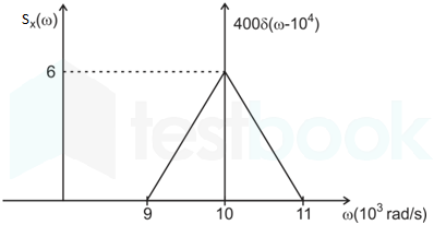
The power spectral density of a real process X(t)\rm X(t) for positive frequencies is as shown below. The value of E[X2(t)]\rm {\rm{E}}\left[ {{X^2}\left( t \right)} \right] and E[X(t)]\rm {\rm{E}}\left[ {X\left( t \right)} \right] is:

  1. ((a))

    6000π,;0\rm \frac{{6000}}{\pi },;0

  2. ((b))

    6400π,0\rm \frac{{6400}}{\pi },0

  3. ((c))

    6400π,20(π2)\frac{{6400}}{\pi },\frac{{20}}{{\left( {\pi \sqrt 2 } \right)}}\rm

  4. ((d))

    6000π,20(π2)\rm \frac{{6000}}{\pi },\frac{{20}}{{\left( {\pi \sqrt 2 } \right)}}

Show Answer
Answer: ((b))

6400π,0\rm \frac{{6400}}{\pi },0

\(\rm E\left[ {{X^2}\left( t \right)} \right] = \frac{1}{{2\pi }}\mathop \smallint \limits_{ - \infty }^\infty {S_x}\left( \omega \right)d\omega \)

Since x(t) is real process the PSD is even function hence above equation can be written as

\(\rm = \frac{2}{{2\pi }}\mathop \smallint \limits_0^\infty {S_x}\left( \omega \right)d\omega \)

\(\rm = \frac{1}{\pi }\mathop \smallint \limits_0^\infty {S_x}\left( \omega \right)d\omega \)

=1π[400+12×2×103×6]\rm = \frac{1}{\pi }\left[ {400 + \frac{1}{2} \times 2 \times {{10}^3} \times 6} \right]

=6400π\rm = \frac{{6400}}{\pi }

E[X(t)]=0\rm E\left[ {X\left( t \right)} \right] = 0 as \(\rm \frac{1}{{2\pi }}\mathop \smallint \limits_{{0^ - }}^{{0^ + }} {S_X}\left( \omega \right)d\omega = 0\)

13

In a baseband communications link, frequencies upto 3500 Hz are used for signaling. Using a raised cosine pulse with 75% excess bandwidth and for no inter-symbol interference, the maximum possible signaling rate in symbols per second is

  1. ((a))

    1750

  2. ((b))

    2625

  3. ((c))

    4000

  4. ((d))

    5250

Show Answer
Answer: ((c))

4000

Concept:

BT = 0.5 Rs(β + 1)

R→ Symbol rate

Rs = (2 × βT)/(β + 1)

Calculations:

β = 0.75

Rs = (2 × 3500)/(0.75 + 1)

= 4000 symbols/sec

14

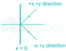
A plane wave propagating in air with E=(8a^x+6a^y+5a^z)ej(ωt+3x4y)Vm\vec E = \left( {8{{\hat a}_x} + 6{{\hat a}_y} + 5{{\hat a}_z}} \right){e^{j\left( {\omega t + 3x - 4y} \right)}}\frac{V}{m} is incident on a perfectly conducting slab positioned at x ≤ 0. The E\vec E field of the reflected wave is

  1. ((a))

    (8a^x6a^y5a^z)ej(ωt+3x+4y)Vm\left( { - 8{{\hat a}_x} - 6{{\hat a}_y} - 5{{\hat a}_z}} \right){e^{j\left( {\omega t + 3x + 4y} \right)}}\frac{V}{m}

  2. ((b))

    (8a^x+6a^y5a^z)ej(ωt+3x+4y)Vm\left( { - 8{{\hat a}_x} + 6{{\hat a}_y} - 5{{\hat a}_z}} \right){e^{j\left( {\omega t + 3x + 4y} \right)}}\frac{V}{m}

  3. ((c))

    (8a^x6a^y5a^z)ej(ωt3x4y)Vm\left( { - 8{{\hat a}_x} - 6{{\hat a}_y} - 5{{\hat a}_z}} \right){e^{j\left( {\omega t - 3x - 4y} \right)}}\frac{V}{m}

  4. ((d))

    (8a^x+6a^y5a^z)ej(ωt3x4y)Vm\left( { - 8{{\hat a}_x} + 6{{\hat a}_y} - 5{{\hat a}_z}} \right){e^{j\left( {\omega t - 3x - 4y} \right)}}\frac{V}{m}

Show Answer
Answer: ((c))

(8a^x6a^y5a^z)ej(ωt3x4y)Vm\left( { - 8{{\hat a}_x} - 6{{\hat a}_y} - 5{{\hat a}_z}} \right){e^{j\left( {\omega t - 3x - 4y} \right)}}\frac{V}{m}

The given waveform can be represented as:

E=(8a^x+6a^y+5a^z)ej(ωt+3x4y)\vec E = \left( {8{{\hat a}_x} + 6{{\hat a}_y} + 5{{\hat a}_z}} \right){e^{j\left( {\omega t + 3x - 4y} \right)}}

A perfect conductor will reflect  E\vec E completely

Et=6a^y+5a^z,;En=8a^x{\vec E_t} = 6{\hat a_y} + 5{\hat a_z},;{\vec E_n} = 8{\hat a_x}

For reflected wave E\vec E tangential component will cancel out tangential component of E\vec E so that net tangential field is zero.

i.e. Ert=(Et)=(6a^y+5a^z){\vec E_{{r_t}}} = - \left( {{{\vec E}_t}} \right) = - \left( {6{{\hat a}_y} + 5{{\hat a}_z}} \right)

Similarly for normal component, Ern=En=8ax{\vec E_{{r_n}}} = - {\vec E_n} = - \vec 8{a_x}

Since, the wave travelling is ‘-x’ & ‘+y’ direction and gets reflected at boundary x ≤ 0, the wave will travel along ‘+x’ & ‘+y’ direction.

Er=(8a^x6a^y5a^z)ej(ωt3x4y)V/m\Rightarrow {\vec E_r} = \left( { - 8{{\hat a}_x} - 6{{\hat a}_y} - 5{{\hat a}_z}} \right){e^{j\left( {\omega t - 3x - 4y} \right)}}V/m

Note: It is an Official GATE Question, asked in GATE EC 2012 Paper. Please understand that Marks to All was allotted for this particular Question. This is because, in any TEM wave, Poynting Theorem must be satisfied according to which the propagation direction and field direction should be perpendicular.

15

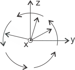
The electric field of a uniform plane electromagnetic wave in free space, travelling along the positive x direction, is given byE=10(a^y+ja^z)ej25x\vec E = 10\left( {{{\hat a}_y} + j{{\hat a}_z}} \right){e^{ - j25x}} The frequency and polarization of the wave, respectively, are:

  1. ((a))

    1.2 GHz and left circular

  2. ((b))

    4 Hz and left circular

  3. ((c))

    1.2 GHz and right circular

  4. ((d))

    4 Hz and right circular

Show Answer
Answer: ((a))

1.2 GHz and left circular

E=10(a^y+ja^z)ej25x\vec E = 10\left( {{{\hat a}_y} + j{{\hat a}_z}} \right){e^{ - j25x}}

⇒ since a^y=a^z\left| {{{\hat a}_y}} \right| = \left| {{{\hat a}_z}} \right|

⇒ Circular, due to phase difference of 90° between y and z, here phase difference between y component and x component is + π/2 hence the wave is left circular.

The x direction is into the plane 

to go in the direction of propogation while curling fingers in direction of rotation in circle, you have to use left hand.

Thus given wave is left hand circularly polarised

β;=;25;;f;=cλ=c×β2π=3×108×252π\beta ; = ;25; \Rightarrow ;f; = \frac{c}{\lambda } = \frac{{c \times \beta }}{{2\pi }} = \frac{{3 \times {{10}^8} \times 25}}{{2\pi }}

⇒ f ≈ 1.2 × 10 9 Hz

16

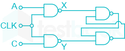
Consider the given circuit. In this circuit, the race around

  1. ((a))

    Does not occur

  2. ((b))

    Occurs when CLK = 0

  3. ((c))

    Occurs when CLK = 1 and A = B = 1

  4. ((d))

    Occurs when CLK = 1 and A = B = 0

Show Answer
Answer: ((a))

Does not occur

The circuit is a SR flip-flop with input A = S and B = R. In SR flip-flop there is no race around condition for any combination of input.

Note :

11 is a not allowed state because the output Q and Q'  will be 1. 

For race around Q should toggle.

It occurs in JK flip flop when J=K=1 and there is unequal propagation delay.

17

The output Y of a 2-bit comparator is logic 1 whenever the 2-bit input A is greater than the 2-bit input B. The number of combinations for which the output is logic 1, is

  1. ((a))

    4

  2. ((b))

    6

  3. ((c))

    8

  4. ((d))

    10

Show Answer
Answer: ((b))

6

The only possible combinations are

A = 01 and B = 0 0

A = 10 and B = 00, 01

A = 11 and B = 00, 01, 10

So there are only 6 combinations

Tips and Tricks:

22n2n2\frac{2^{2n} - 2^n}{2}

where n = 2 bit

18

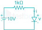
The i-v characteristics of the diode in the circuit given below are

\(i= \left{ \begin{matrix} \frac{v-0.7}{500}A && v \ge 0.7 V \\ 0 A && v < 0.7 V \end{matrix}\right.\)

The current in the circuit is

  1. ((a))

    10 mA

  2. ((b))

    9.3 mA

  3. ((c))

    6.67 mA

  4. ((d))

    6.2 mA

Show Answer
Answer: ((d))

6.2 mA

Let's consider v >.7 and the diode is forward biased. 

By applying KVL, we get

10 - I × 1k - v = 0

10 -[(v-.7)/(500)] × 1000 - v = 0

⇒ v = 3.8 V 

And v > .7 and our assumption is correct,

i =[(v-.7)/(500)] = [3.8 - 0.7]/500 = 6.2 mA

19

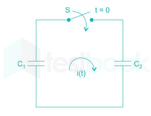
In the following figure, C1 and C2 are ideal capacitors. C1 has been charged to 12 V before the ideal switch S is closed at t = 0. The current i(t) for all t is

  1. ((a))

    Zero

  2. ((b))

    A step function

  3. ((c))

    An exponentially decaying function

  4. ((d))

    An impulse function

Show Answer
Answer: ((d))

An impulse function

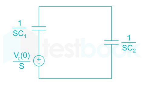
The S – domain equivalent circuit is

I(S)=Vc(0)S1C1S+1C2S=Vc(0)(1C1+1C2)%MathType!End!2!1! I\left( S \right) = \frac{{\frac{{{V_c}\left( 0 \right)}}{S}}}{{\frac{1}{{{C_1}S}} + \frac{1}{{{C_2}S}}}} = \frac{{{V_c}\left( 0 \right)}}{{\left( {\frac{1}{{{C_1}}} + \frac{1}{{{C_2}}}} \right)}}\% MathType!End!2!1!

Vc(0) = 12 V

I(S)=(C1C2C1+C2)(12)%MathType!End!2!1!I\left( S \right) = \left( {\frac{{{C_1}{C_2}}}{{{C_1} + {C_2}}}} \right)\left( {12} \right)\% MathType!End!2!1!

I(S) = 12 Ceq

Taking Inverse Laplace transform for the current in the time domain.

i(t) = 12 Ceq δ(t) 

The above equation shows that it's an impulse.

20

The average power delivered to an impedance (4 – j3) Ω by a current 5 cos (100πt + 100) A is

  1. ((a))

    44.2 W

  2. ((b))

    50 W

  3. ((c))

    62.5 W

  4. ((d))

    125 W

Show Answer
Answer: ((b))

50 W

In phasor form:

Z = 4 – j3

Z = 5 ∠-36.86° Ω

I = 5 ∠100° A

Average power delivered will be:

Pavg=12I2Zcosθ%MathType!End!2!1!{P_{avg}} = \frac{1}{2}{\left| I \right|^2}Zcos\theta \% MathType!End!2!1!

= (½) × 25 × 5 cos 36.86°

= 50 W

Alternate Approach:

The power delivered to the load will simply be the power dissipated by the resistor R, i.e.

Pdelivered = IRMS2 R

With Im = 5, IRMS will be:

IRMS=52I_{RMS} = \frac{5}{\sqrt 2}

Pdelivered=(52)2×4P_{delivered} = (\frac{5}{\sqrt 2})^2\times 4

Pdelivered=252×4=50 WP_{delivered} =\frac{25}{2}\times 4 = 50~W

21

The unilateral Laplace transform of f(t) is 1s2+s+1\frac{1}{s^2+s+1}. The unilateral Laplace transform of t f(t) is

  1. ((a))

    s(s2+s+1)2-\frac{s}{(s^2+s+1)^2}

  2. ((b))

    2s+1(s2+s+1)2-\frac{2s+1}{(s^2+s+1)^2}

  3. ((c))

    s(s2+s+1)2\frac{s}{(s^2+s+1)^2}

  4. ((d))

    2s+1(s2+s+1)2\frac{2s+1}{(s^2+s+1)^2}

Show Answer
Answer: ((d))

2s+1(s2+s+1)2\frac{2s+1}{(s^2+s+1)^2}

Concept

Multiplication of function in one domain corresponds to the differentiation in another domain

If f(t) having the Laplace transform F(s) then t ⋅ f(t) will have the transform as

  t f(t) ↔dF(s)ds - \frac{{dF\left( s \right)}}{{ds}}

Calculation:

Given function f(t) is . And  g(t) = t ⋅ f(t)

Laplace transform of g(t) is:

L[g(t)]=dds(1s2s+1)L[g(t)] = - \frac{d}{{ds}}\left( {\frac{1}{{{s^2}s + 1}}} \right)

=d(1)ds(s2+s+1)1×d(S2+S+1)ds(S2+S+1)2 = - \frac{{\frac{{d\left( 1 \right)}}{{ds}}\left( {{s^2} + s + 1} \right) - 1 \times \frac{{d\left( {{S^2} + S + 1} \right)}}{{ds}}}}{{{{\left( {{S^2} + S + 1} \right)}^2}}}

=(01(2s+1)(s2+s+1)2) = - \left( {\frac{{0 - 1\left( {2s + 1} \right)}}{{{{\left( {{s^2} + s + 1} \right)}^2}}}} \right)

=2s+1(s2+s+1)2 = \frac{{2s + 1}}{{{{\left( {{s^2} + s + 1} \right)}^2}}}

22

With initial condition x(1) = 0.5 , the solution of the differential equation tdxdt+x=tt\frac{dx}{dt}+x=t is

  1. ((a))

    x=t12x=t-\frac{1}{2}

  2. ((b))

    x=t212x=t^2-\frac{1}{2}

  3. ((c))

    x=t22x=\frac{t^2}{2}

  4. ((d))

    x=t2x=\frac{t}{2}

Show Answer
Answer: ((d))

x=t2x=\frac{t}{2}

Given differential equation is tdxdt+x;=;tt\frac{{dx}}{{dt}} + x; = ;{t}

;dxdt+1tx;=;1\Rightarrow ;\frac{{dx}}{{dt}} + \frac{1}{t}x; = ;1

This is a linear differential equation in t.

I.F.;=;e1tdt;=;elogt;=;tI.F.; = ;{e^{\smallint \frac{1}{t}dt}}; = ;{e^{\log t}}; = ;t

The solution is,

x.(IF);=;1.(IF)dt+cx.t;=;tdt+c ;xt;=;t22+c\begin{array}{l} x.(IF); = ;\smallint 1.(IF)dt + c\Rightarrow x.t; = ;\smallint tdt + c\ \Rightarrow ;xt; = ;\frac{{{t^2}}}{2} + c \end{array}

Given x(1) = .5 ⇒ c = 0

The solution is x;=;t2x; = ;\frac{{{t}}}{2}

23

The diodes and capacitors in the circuit shown are ideal. The voltage V(t) across the diode D1 is:

  1. ((a))

    cos(ωt) – 1

  2. ((b))

    sin (ωt)

  3. ((c))

    1 – cos (ωt)

  4. ((d))

    1 – sin (ωt)

Show Answer
Answer: ((a))

cos(ωt) – 1

At t = 0+, D1 will be ON and D2 will be OFF, and the capacitor will be instantly charged to 1 V as the current offered will be infinite.

This 1 V at the capacitor will reverse bias both the diodes, i.e. both D1 and D2 will be OFF and the voltage v(t) will be calculated as shown:

– cosωt + 1 + V(t) = 0

V(t) = cosωt - 1 

Hence option (1) is correct

24

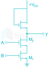
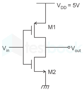
The circuit shown in the figure is:

  1. ((a))

    OR gate 

  2. ((b))

    NOR gate 

  3. ((c))

    NAND gate 

  4. ((d))

    AND gate 

Show Answer
Answer: ((c))

NAND gate 

Concept:

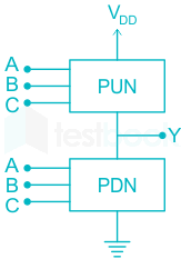
MOS logic circuit consists of two network transistors, a pull-down network (PDN) and a Pull-up Network (PUN) as shown:

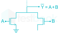
The PDN and PUN are connected in parallel to form OR logic function and they are connected in series to form AND logic as shown:


Application:

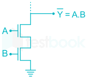
Since we have the two MOS transistors connected in series, the resultant output will be the AND operation, with inverted output, i.e.

Y=AB\overline Y= {AB}

Y=ABY=\overline {AB}

25

A source generates three symbols with probability 0.25, 0.25, 0.50 at a rate of 3000 symbols per second. Assuming independent generation of symbols, the most efficient source encoder would have average bit rate of

  1. ((a))

    6000 bits/sec

  2. ((b))

    4500 bits/sec

  3. ((c))

    3000 bits/sec 

  4. ((d))

    1500 bits/sec

Show Answer
Answer: ((b))

4500 bits/sec

Concept:

Information associated with the event is “inversely” proportional to the probability of occurrence.

Entropy: The average amount of information is called the “Entropy”.

\(H = ;\mathop \sum \limits_i {P_i}{\log _2}\left( {\frac{1}{{{P_i}}}} \right);bits/symbol\)

Rate of information = r.H

Calculation:

Given:

Three symbols with a probability of 0.25, 0.25, and 0.50 at the rate of 3000 symbols per second.

Entropy is given as;

 H=0.25log2(10.25)+0.25log210.25+0.5log210.5; H = 0.25{\log _2}\left( {\frac{1}{{0.25}}} \right) + 0.25{\log _2}\frac{1}{{0.25}} + 0.5{\log _2}\frac{1}{{0.5}};

=0.25×2+0.25×2+0.5×1 = 0.25 \times 2 + 0.25 \times 2 + 0.5 \times 1

= 1.5

Rate of information = r.H

= 1.5 × 3000

= 4500 bits/sec

26

For a co-axial cable, inner diameter of outer conductor and diameter of inner conductor are 1 cm and 0.01 cm respectively. If dielectric constant \(\epsilon{r}\) of the material filling in cable is 4, characteristic impedance of the co-axial cable is____Ω\Omega

Use μo=4π×107H/m, ϵo=10936πF/m{\mu _o} = 4\pi \times {10^{ - 7}}H/m,\ \epsilon{_o} = \frac{{{{10}^{ - 9}}}}{{36\pi }}F/m

  1. ((a))

    330 ohm

  2. ((b))

    150 ohm

  3. ((c))

    200 ohm

  4. ((d))

    138 ohm

Show Answer
Answer: ((d))

138 ohm

Inner diameter of outer conductor, D = 1 cm

Diameter of inner conductor, d = 0.01 cm

Characteristic impedance of coaxial cable, 

Z0=12πμϵ×ln(Dd)=138εrlogDd{Z_0} = \frac{1}{2\pi }\sqrt {\frac{\mu }{\epsilon}} \times ln\left( {\frac{D}{d}} \right) = \frac{{138}}{{\sqrt {{\varepsilon _r}} }}\log \frac{D}{d}

Zo=1382log10.01=138;Ω \Rightarrow {Z_o} = \frac{{138}}{2}\log \frac{1}{{0.01}} = 138;{\rm{\Omega }}

27

The radiation pattern of an antenna in spherical co-ordinates is given by

F(θ)=cos2θ,0θ;π;/2F\left( \theta \right) = {\cos ^2}\theta ,0 \le \theta \le ;\pi ;/2

The directivity of the antenna is

  1. ((a))

    10 dB

  2. ((b))

    12.6 dB

  3. ((c))

    11.5 dB

  4. ((d))

    18 dB

Show Answer
Answer: ((a))

10 dB

Radiation pattern F(θ)=cos2θ,0θ;π;/2F\left( \theta \right) = {\cos ^2}\theta ,0 \le \theta \le ;\pi ;/2

U(θ) = F2(θ)

Directivity of antenna is given as

D=4πUmaxPradD = \frac{{4\pi {U_{max}}}}{{{P_{rad}}}}

\({P_{rad}} = \mathop \smallint \limits_{\phi = 0}^{2\pi } \mathop \smallint \limits_{\theta = 0}^{\frac{\pi }{2}} \left( {{{\cos }^4}{\rm{\theta }}} \right)\left( {sin\theta } \right)d\theta .d\phi = 2\pi \mathop \smallint \limits_{\theta = 0}^{\frac{\pi }{2}} \left( {{{\cos }^4}{\rm{\theta }}} \right)\left( {\sin {\rm{\theta).(d\theta }}}\right)\)

\(= 2\pi \mathop \smallint \limits_{ - 1}^0 {t^4}dt = 2\pi \left. {\frac{{{t^5}}}{5}} \right|_{ - 1}^0 = \frac{{2\pi }}{5}\)

Umax=cos4θmax=1{U_{max}} = {\left. {{{\cos }^4}\theta } \right|_{max}} = 1

⇒ Directivity D=4π(1)(2π5)=1010log10=10;dBD = \frac{{4\pi \left( 1 \right)}}{{\left( {\frac{{2\pi }}{5}} \right)}} = 10 \Rightarrow 10\log 10 = 10;dB

28

If x[n] = (1/3)|n| - (1/2)n u[n], then the region of convergence (ROC) of its z-transforms in the z-plane will be

  1. ((a))

    z>3\left| z \right| > 3

  2. ((b))

    13<z<12\frac{1}{3} < \left| z \right| < \frac{1}{2}

  3. ((c))

    12<z<3\frac{1}{2} < \left| z \right| < 3

  4. ((d))

    13<z\frac{1}{3} < \left| z \right|

Show Answer
Answer: ((c))

12<z<3\frac{1}{2} < \left| z \right| < 3

x[n]=(13)n(12)nu[n] =(13)nu[n]+(13)n1u[n1](12)nu[n]\begin{array}{l} x\left[ n \right] = {\left( {\frac{1}{3}} \right)^{\left| n \right|}} - {\left( {\frac{1}{2}} \right)^n}u\left[ n \right]\ = {\left( {\frac{1}{3}} \right)^n}u\left[ n \right] + {\left( {\frac{1}{3}} \right)^{n - 1}}u\left[ { - n - 1} \right] - {\left( {\frac{1}{2}} \right)^n}u\left[ n \right] \end{array}

Taking Z-transform

\(\begin{array}{l} X\left[ z \right] = \mathop \sum \limits_{n = - \infty }^\infty {\left( {\frac{1}{3}} \right)^n}{z^{ - n}}u\left[ n \right] + \mathop \sum \limits_{n = - \infty }^\infty {\left( {\frac{1}{3}} \right)^{ - n}}{z^{ - n}}u\left[ { - n - 1} \right] - \mathop \sum \limits_{n = - \infty }^\infty {\left( {\frac{1}{2}} \right)^n}{z^{ - n}}u\left[ n \right]\ = \mathop \sum \limits_{n = 0}^\infty {\left( {\frac{1}{3}} \right)^n}{z^{ - n}} + \mathop \sum \limits_{n = - \infty }^{ - 1} {\left( {\frac{1}{3}} \right)^{ - n}}{z^{ - n}} - \mathop \sum \limits_{n = 0}^\infty {\left( {\frac{1}{2}} \right)^n}{z^{ - n}}\ = \underbrace {\mathop \sum \limits_{n = 0}^\infty {{\left( {\frac{1}{{3Z}}} \right)}^n}}I + \underbrace {\mathop \sum \limits{m = 1}^\infty {{\left( {\frac{Z}{3}} \right)}^m}}{II} - \underbrace {\mathop \sum \limits{n = 0}^\infty {{\left( {\frac{1}{{2Z}}} \right)}^n}}_{III} \end{array}\)

Series I converges if 13Z<1orZ>13\left| {\frac{1}{{3Z}}} \right| < 1or\left| Z \right| > \frac{1}{3}

Series II converges if 13z<1 or Z<3\left| {\frac{1}{3}z} \right| < 1\ or\ \left| Z \right| < 3

Series III converges if 12Z<1 or Z>12\left| {\frac{1}{{2Z}}} \right| < 1\ or\ \left| Z \right| > \frac{1}{2}

Region of convergence of X(Z) will be intersection of above three

So, ROC  12<Z<3\frac{1}{2}< |Z| < 3.

29

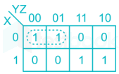
In the sum of products function f (X, Y, Z) = ∑ (2, 3, 4, 5) , the prime implicants are

  1. ((a))

    X̅Y, XY̅

  2. ((b))

    X̅Y, XY̅Z̅, XY̅Z

  3. ((c))

    X̅YZ̅, X̅YZ, XY̅

  4. ((d))

    X̅YZ̅, X̅YZ, XY̅Z̅, XY̅Z

Show Answer
Answer: ((a))

X̅Y, XY̅

Prime implicant is a minterm, which are obtained by combining maximum possible adjacent cell in k-map

F(x,y,z)=xˉyˉ+xyF\left( {x,y,z} \right) = \bar x\bar y + xy

30

A system with transfer function G(s) shown below is excited by sin(ωt) then the steady state output of the system is zero at

G(S)=(S2+16)(S+2)(S+1)(S+3)(S+5)G\left( S \right) = \frac{{\left( {{S^2} + 16} \right)\left( {S + 2} \right)}}{{\left( {S + 1} \right)\left( {S + 3} \right)\left( {S + 5} \right)}}

  1. ((a))

    ω = 1 rad/s

  2. ((b))

    ω = 2 rad/s

  3. ((c))

    ω = 3 rad/s

  4. ((d))

    ω = 4 rad/s

Show Answer
Answer: ((d))

ω = 4 rad/s

r(t) = sin(ωt) ⇒ R(s) is not zero for all time duration for any value of ω

C(S) = G(S) R(S)

For C(S) at steady state to be zero

|(GS)| = 0

∵ R(S) ≠ 0

G(jω)=(16ω2)(jω+2)(jω+1)(jω+3)(jω+5)=0 \Rightarrow \left| {G\left( {j\omega } \right)} \right| = \left| {\frac{{\left( {16 - {\omega ^2}} \right)\left( {j\omega + 2} \right)}}{{\left( {j\omega + 1} \right)\left( {j\omega + 3} \right)\left( {j\omega + 5} \right)}}} \right| = 0

Only possible if

16 – ω2 = 0

⇒ ω = 4 rad/s

31

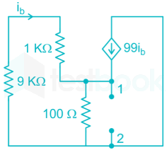
The impedance looking into nodes 1 and 2 in the given circuit is

  1. ((a))

    50 Ω

  2. ((b))

    100 Ω

  3. ((c))

    5 KΩ

  4. ((d))

    10.1 KΩ

Show Answer
Answer: ((a))

50 Ω

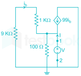
Assume a voltage source V between 1 and 2 ,

then VI=impendance\frac{V}{I} = impendance at 1 and 2

ib=0V10 KΩ{i_b} = \frac{{0 - V}}{{10\ K{\rm{\Omega }}}}         ___________(1)

Apply Nodal analysis then

ib+V10099ibI=0- {i_b} + \frac{V}{{100}} - 99{i_b} - I = 0

V = 104 ib + 100 I        ___________(2)

From (1) and (2) we get

V=104(V104)+100 IV = {10^4}\left( {\frac{{ - V}}{{{{10}^4}}}} \right) + 100\ I

2V = 100 I

Impendence =VI=50 Ω= \frac{V}{I} = 50\ {\rm{\Omega }}

∴ Option (1) is correct

32

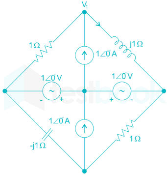
In the circuit shown below, the current through the inductor is

  1. ((a))

    21+jA\frac{2}{{1 + j}}A

  2. ((b))

    11+jA\frac{{ - 1}}{{1 + j}}A

  3. ((c))

    11+jA\frac{1}{{1 + j}}A

  4. ((d))

    0 A

Show Answer
Answer: ((c))

11+jA\frac{1}{{1 + j}}A

Applying nodal analysis at top node

V1+101+V1+10j1=10\frac{{{V_1} + 1\angle 0^\circ }}{1} + \frac{{{V_1} + 1\angle 0^\circ }}{{j1}} = 1\angle 0^\circ

V1 = (j1 + 1) + j1 + 1 ∠ 0° = j1

V1=11+j1 I1=V1=V1+10j1=1j+1+1j1=j(1+j)j=1(1+j)A\begin{array}{l} {V_1} = \frac{{ - 1}}{{1 + j1}}\ {I_1} = {V_1} = \frac{{{V_1} + 1\angle 0^\circ }}{{j1}} = \frac{{\frac{{ - 1}}{{j + 1}} + 1}}{{j1}} = \frac{j}{{\left( {1 + j} \right)j}} = \frac{1}{{\left( {1 + j} \right)}}A \end{array}

33

Given f(z)=1z+12z+3f(z)=\frac{1}{z+1}-\frac{2}{z+3}. If C is a counterclockwise path in the z-plane such that |z + 1| = 1, the value of 12πicf(z)dz\frac{1}{2\pi i}\int_c f(z)dz is

  1. ((a))

    -2

  2. ((b))

    -1

  3. ((c))

    1

  4. ((d))

    2

Show Answer
Answer: ((c))

1

f(z);=;1z+12z+3;=;z+1(z+1)(z+3)f\left( z \right); = ;\frac{1}{{z + 1}} - \frac{2}{{z + 3}}; = ;\frac{{ - z + 1}}{{\left( {z + 1} \right)\left( {z +3} \right)}}

The poles of f(z) are - 1 and -3 and -3 is outside of the circle |z + 1| = 1.

By Cauchy’s formula,

f(z)zadz;=;2πif(a) z+1(z+3)(z+1)dz;=;z+1(z+3)(z+1)dz\begin{array}{l} \smallint \frac{{f\left( z \right)}}{{z - a}}dz; = ;2\pi if\left( a \right)\ \smallint \frac{{ - z + 1}}{{\left( {z + 3} \right)\left( {z +1} \right)}}dz; = ;\smallint \frac{{\frac{{ - z +1}}{{\left( {z +3} \right)}}}}{{\left( {z + 1} \right)}}dz \end{array}

By Cauchy’s formula,

;2πif(1);=;2πi((1)+11+3);=;2πi ;12πif(z)dz;=;1\begin{array}{l} \Rightarrow ;2\pi if\left( { - 1} \right); = ;2\pi i\left( {\frac{{-(-1) + 1}}{{ - 1 + 3}}} \right); = ;2\pi i\ \Rightarrow ;\frac{1}{{2\pi i}}\smallint f\left( z \right)dz; = ;1 \end{array}

34

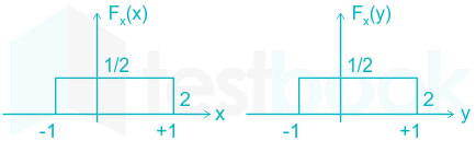
Two independent random variables X and Y are uniformly distributed in the interval [–1,1]. The probability that max[X, Y] is less than 1/2 is

  1. ((a))

    3/4

  2. ((b))

    9/16

  3. ((c))

    1/4

  4. ((d))

    2/3

Show Answer
Answer: ((b))

9/16

P(max(X,Y) < .5) = P(X <.5, Y < 0.5)

Since X and Y are independent random variable, therefore

P(X <.5, Y < 0.5) = P(X < .5) P(Y < .5)

X and Y are uniformly distributed in [-1,1]

PDF of X and Y are

Thus,

P(X > 2) P(Y > 2)

35

If x = √-1, then the value of xx is

  1. ((a))

    e-π/2

  2. ((b))

    eπ/2

  3. ((c))

    x

  4. ((d))

    1

Show Answer
Answer: ((a))

e-π/2

Let A = xx

Taking logarithm both the sides.

Log A = x log x = i log (0 + x)

As |x| = 1 and arg (x) = π/2,

Log A = x(log1 + xπ/2) = x(0 + x π/2)

Log A = -π/2

Hence, A = e- π/2

36

The source of a silicon (ni= 1010 per cm3) n-channel MOS transistor has an area of 1 sq μm and a depth of 1 μm. If the dopant density in the source is 1019/cm3, the number of holes in the source region with the above volume is approximately,

  1. ((a))

    10710^7

  2. ((b))

    100100

  3. ((c))

    1010

  4. ((d))

    00

Show Answer
Answer: ((d))

00

The volume of the region is calculated as:

=1μm2×1μm = 1\mu m^2 × 1\mu m( = {10^{ - 18}}{m^3}\)

For an n-channel MOS capacitor, the type of substrate is p-type.

Also, the type of doping for the source and the drain of an n-channel MOSFET is n-type.

The dopant density at the source is the donor density only as the source is n-type.

The concentration of holes in the source region will be calculated from the mass action law by:

ni2ND=(1010)21019=10 cm3=107m3\frac{{n_i^2}}{{{N_D}}} = \frac{{{{\left( {{{10}^{10}}} \right)}^2}}}{{{{10}^{19}}}}=10\ cm^{-3}=10^{7} m^{3}(\)

∴ The number of holes in that volume will be:

=10-18 × 107 = 10-11 ≈ 0

37

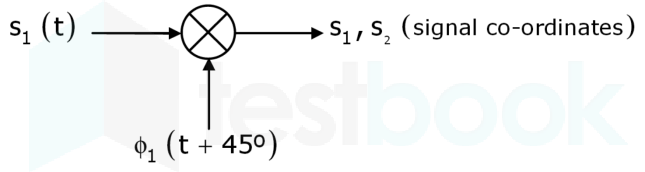
A BPSK schemes operating over an AWGN channel with noise spectral density No/2\rm {N_o}/2 uses equiprobable signals s1(t)=2ETsin(ωct)\rm {s_1}\left( t \right) = \sqrt {\frac{{2E}}{T}} \sin \left( {{\omega _c}t} \right) and s2(t)=2ETsin(ωct)\rm {s_2}\left( t \right) = - \sqrt {{\frac{{2E}}{T}}} \sin \left( {{\omega _c}t} \right) over the symbol interval, (0,T)\rm (0, T). If the local oscillator in a coherent receiver is ahead in phase by 45°\rm 45° with respect to the received signal, the probability of error in the resulting system is:

  1. ((a))

    Q(2ENo)\rm Q\left( {\sqrt {\frac{{2E}}{{No}}} } \right)

  2. ((b))

    Q(E4No)\rm Q\left( {\sqrt {\frac{E}{{4No}}} } \right)

  3. ((c))

    Q(E2No)\rm Q\left( {\sqrt {\frac{E}{{2No}}} } \right)

  4. ((d))

    Q(ENo)\rm Q\left( {\sqrt {\frac{E}{{No}}} } \right)

Show Answer
Answer: ((d))

Q(ENo)\rm Q\left( {\sqrt {\frac{E}{{No}}} } \right)

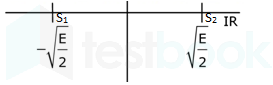
Based on the information given for the two symbols waveforms, we see that the basis function is 2Tsin(ωct)\rm \sqrt {\frac{2}{T}} \sin \left( {{\omega _c}t} \right). Now the oscillator frequency is

2Tsin(ωct+45)\rm \sqrt {\frac{2}{T}} \sin \left( {{\omega _c}t + {{45}^\circ }} \right)

Using this, we calculate the vectors of demodulated symbols of  s1(t)\rm {s_1}\left( t \right) and s2(t)\rm {s_2}\left( t \right) along the basis function and get the following result.

S1=E2\rm {S_1} = \sqrt {\frac{E}{2}} and S2=E2\rm {S_2} = - \sqrt {\frac{E}{2}}

Now, distance between vectors d=2E2\rm d = 2\sqrt {\frac{E}{2}}

Now, using the relation that Pe=Q(d22No)=Q(4×E22No)=Q(ENo)\rm {P_e} = Q\left( {\sqrt {\frac{{{d^2}}}{{2{N_o}}}} } \right) = Q\left( {\sqrt {\frac{{4 \times \frac{E}{2}}}{{2{N_o}}}} } \right) = Q\left( {\sqrt {\frac{E}{{{N_o}}}} } \right)

Alternate Solution:

For BPSK

For coherent detection when there is phase synchronization between the carrier and received signal:

Pe=Q(2EbNo)P_e= Q\left( {\sqrt {\frac{2E_b}{{{N_o}}}} } \right)

For coherent detection when there is phase shift of ϕ  between the carrier and received signal:

Pe=Q(2EbCos2ϕNo)P_e= Q\left( {\sqrt {\frac{2E_bCos^2\phi}{{{N_o}}}} } \right)

Substituting the values Cos2 ϕ = 1/2

Pe=Q(ENo)P_e = Q\left( {\sqrt {\frac{E}{{{N_o}}}} } \right)

38

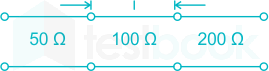
A transmission line with a characteristic impedance of 100 Ω is used to match a 50 Ω section to a 200 Ω section. If the matching is to be done both at 429 MHz and 1 GHz, the length of the transmission line can be approximately:

  1. ((a))

    82.5 cm

  2. ((b))

    1.05 m

  3. ((c))

    1.58 m

  4. ((d))

    1.75 m

Show Answer
Answer: ((c))

1.58 m

For 429 MHz, ;l1=λ14=c4f1;{l_1} = \frac{{{\lambda _1}}}{4} = \frac{c}{{4{f_1}}}

l1=0.175;m\Rightarrow {l_1} = 0.175;m

for 1GHz, l2=λ24=c4f2=0.075;m{l_2} = \frac{{{\lambda _2}}}{4} = \frac{c}{{4{f_2}}} = 0.075;m

The length of the transmission line l should be an odd integral multiple of both l1l_1and l2l_2

l=LCM(l1,l2)=0.525m \Rightarrow l = LCM\left( {{l_1},{l_2}} \right) = 0.525m .....(0.525=3×0.175=7×0.075)(0.525 = 3 × 0.175 = 7 × 0.075)

Since ll is not in options we have take integral of l:

l' = 3l = 1.575 m ≈ 1.58 m

39

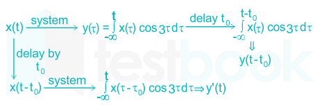
The input x(t) and output y(t) of a system are related as y(t)=tx(τ)cos(3τ)dτ.y(t)=\int_{-\infty}^t x(\tau)cos(3\tau)d\tau. The system is

  1. ((a))

    time-invariant and stable

  2. ((b))

    stable and not time-invariant

  3. ((c))

    time-invariant and not stable

  4. ((d))

    not time-invariant and not stable

Show Answer
Answer: ((d))

not time-invariant and not stable

  1. Time Invariant and Time Variant System:

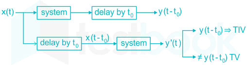
If in a system, a delay in the input leads to same delay in the output, then such system is known as time invariant system. Otherwise It will be time variant system.

  1. Stable and Unstable system:

The system is sold to be stable only when the bounded output for the input.

For a bounded input if output is unbounded then system is said to be UNSTABLE.

Condition:

\(\mathop \smallint \nolimits_{ - \infty }^\infty \left| {h\left( t \right)} \right|dt < \infty \) or finite.

Where h(t) is impulse response of system.

Solution:

Given, \(y\left( t \right) = \mathop \smallint \nolimits_{ - \infty }^t x\left( \tau \right)\cos \left( {3\tau} \right)d\tau\) 

Check for time-invariance:

Since y’(t) ≠ y (t – t0) so it is time-variant

Stability:

Suppose input x(t) = cos 3t

\(y\left( t \right) = \mathop \smallint \nolimits_{ - \infty }^t {\cos ^2}3\tau dt = \mathop \smallint \nolimits_{ - \infty }^t \left( {\frac{{1 + \cos 6\tau }}{2}} \right)d\tau ;\)

\(y\left( t \right) = [\left. {\frac{1}{2}t\tau } \right|{ - \infty }^t + \frac{1}{2}\sin \left. {\frac{{6\tau }}{6}} \right|{ - \infty }^t\)

Since y(t) → ∞, it is unbounded of P so this is an unstable system.

TRICK:

→ check for stability: try to find at least one input value for which output will be unbounded.

e.g. y(t)=ex(t5)t5y\left( t \right) = \frac{{{e^x}\left( {t - 5} \right)}}{{t - 5}} at t = 5 y(t) → ∞ - unbounded.

→ check for variance: If any coefficient if input is function of time (t) then it will be time variant.

e.g. tx(t), etx(t), sin t x(t)

40

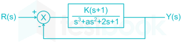
The feedback system shown below oscillates at 2 rads/sec. when

  1. ((a))

    k = 2 and a = 0.75

  2. ((b))

    k = 4 and a = 0.5

  3. ((c))

    k = 3 and a = 0.75

  4. ((d))

    k = 2 and a = 0.5

Show Answer
Answer: ((a))

k = 2 and a = 0.75

The characteristic equation is s3 + as2 + (k + 2) s + (k + 1) = 0

Routh array

s31k + 2
s2ak + 1
s1a(k+2)(k+1)a\frac{{a\left( {k + 2} \right) - \left( {k + 1} \right)}}{a}
s0k + 1
<br>

System oscillates if row of zero occurs

That occurs when a(k+2)(k+1)a=0\frac{{a\left( {k + 2} \right) - \left( {k + 1} \right)}}{a} = 0

ak + 2a = k + 1

a=k+1k+2a = \frac{{k + 1}}{{k + 2}}

System oscillates at ω = 2 rad/sec

as2 + k + 1 = 0

k+1k+2s2+k+1=0\frac{{k + 1}}{{k + 2}}{s^2} + k + 1 = 0

s2 = – (k + 2)

s=±k+2;js = \pm \sqrt {k + 2} ;j

Comparing

k = 2

a=k+1k+2=2+12+2=0.75a = \frac{{k + 1}}{{k + 2}} = \frac{{2 + 1}}{{2 + 2}} = 0.75

41

The Fourier transform of a signal h(t) is H (jω) = (2 cosω ) (sin2ω) / ω . The value of h(0) is

  1. ((a))

    ¼

  2. ((b))

    ½

  3. ((c))

    1

  4. ((d))

    2

Show Answer
Answer: ((c))

1

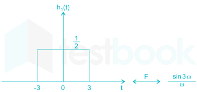
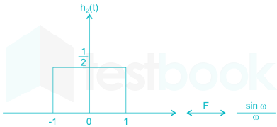
H(jω)=(2cosω)(sin2ω)ω =sin3ωω+sinωω\begin{array}{l} H\left( {j\omega } \right) = \frac{{\left( {2\cos \omega } \right)\left( {\sin 2\omega } \right)}}{\omega }\ = \frac{{\sin 3\omega }}{\omega } + \frac{{sin\omega }}{\omega } \end{array}

We know that the inverse Fourier transform of sinc function is a rectangular function.

A rect(tτ)Aτ Sa(ωτ2)A~rect(\frac{t}{\tau}) \leftrightarrow A \tau ~Sa(\frac{\omega \tau}{2})

Now,

Sa(ωτ2)=sin (ωτ2)ωτ2Sa(\frac{\omega \tau}{2}) = \frac{sin~(\frac{\omega \tau}{2})}{\frac{\omega \tau}{2}}

\(\frac{sin 3\omega}{\omega} = 3 \frac{sin(3\omega)}{3\omega}\)

By comparing, we get

τ/2=3,Aτ=3\tau/2 = 3, A\tau = 3

hence, A = 0.5

2) 

\(\frac{sin \omega}{\omega} = 1\times \frac{sin(\omega \times 1)}{\omega \times 1}\)

By comparing, we get

τ/2=1,Aτ=1\tau/2 = 1, A\tau = 1

hence, A = 0.5


So, inverse Fourier transform of H (jω)

h(t) = h(t) + h2(t)

h(0) = h1(0) + h2­­(0)

12+12=1\frac{1}{2}+\frac{1}{2} = 1

42

State variable description of an LTI system is given by

\(\left[ {\begin{array}{{20}{c}} {{{\dot x}_1}}\ {{{\dot x}_2}}\ {{{\dot x}_3}} \end{array}} \right] = \left[ {\begin{array}{{20}{c}} 0&{{a_1}}&0\ 0&0&{{a_2}}\ {{a_3}}&0&0 \end{array}} \right]\left[ {\begin{array}{{20}{c}} {{x_1}}\ {{x_3}}\ {{x_3}} \end{array}} \right] + \left[ {\begin{array}{{20}{c}} 0\ 0\ 1 \end{array}} \right]U\)

\(Y = \left[ {\begin{array}{{20}{c}} 1&0&0 \end{array}} \right]\left[ {\begin{array}{{20}{c}} {{x_1}}\ {{x_2}}\ {{x_3}} \end{array}} \right]\)

Where Y is the output and u is input. System is controllable for

  1. ((a))

    a1 ≠ 0, a2 = 0, a3 ≠ 0

  2. ((b))

    a1 = 0, a2 ≠ 0, a3 = 0

  3. ((c))

    a1 = 0, a2 ≠ 0, a3 ≠ 0

  4. ((d))

    a1 ≠ 0, a2 ≠ 0, a3 = 0

Show Answer
Answer: ((d))

a1 ≠ 0, a2 ≠ 0, a3 = 0

\({Q_c} = \left[ {\begin{array}{*{20}{c}} B&{AB}&{{A^2}B} \end{array}} \right]\)

\({Q_c} = \left[ {\begin{array}{*{20}{c}} 0&0&{{a_1}{a_2}}\ 0&{{a_2}}&0\ 1&0&0 \end{array}} \right]\)

System is controllable if |QC| ≠ 0

a1a2 (0 – a2) ≠ 0

a1a220- {a_1} \cdot a_2^2 \ne 0

Hence condition for controllability is

a1 ≠ 0, a2 ≠ 0, a3 = 0

43

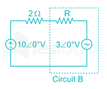
Assuming both the voltage sources are in phase, the value of R for which maximum power is transferred from circuit A to circuit B is

  1. ((a))

    0.8 Ω

  2. ((b))

    1.4 Ω

  3. ((c))

    2 Ω

  4. ((d))

    2.8 Ω

Show Answer
Answer: ((a))

0.8 Ω

We obtain Thevenin equivalent of circuit B

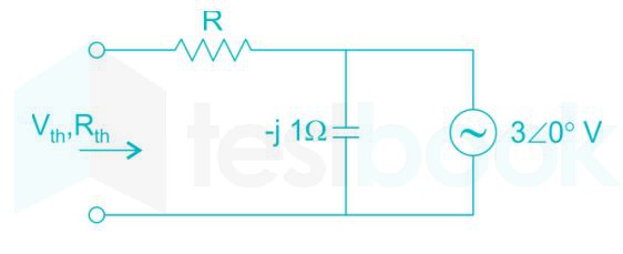
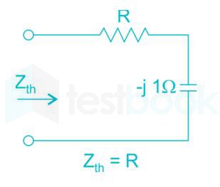
Thevenin impedance:

Thevenin Voltage: Vth = 3∠0° V

Now, circuit becomes as

Current in the circuit,

I1 = (10-3)/(2 + R)

Power transfer from circuit A to B

P = (I1)2R + 3 I1

= (42 + 70 R)/(2 + R)2

dP/dR = 0

⇒ (2 + R) [(2 + R) 70 – (42 + 70 R) 2] = 0

⇒ R = 0.8 Ω

44

Consider the differential equation

\(\frac{{{d^2}y\left( t \right)}}{{d{t^2}}} + 2\frac{{dy\left( t \right)}}{{dt}} + y\left( t \right) = \delta \left( t \right)\ with\ y\left( t \right){|{t = {0^ - }}} = - 2\ and\ \frac{{dy}}{{dt}}{|{t = {0^ - }}} = 0\)

The numerical value of dydtt=0+\frac{{dy}}{{dt}}{|_{t = {0^ + }}} is

  1. ((a))

    -2

  2. ((b))

    -1

  3. ((c))

    0

  4. ((d))

    1

Show Answer
Answer: ((d))

1

d2ydt2+2dydt+y=δ(t)\frac{{{d^2}y}}{{d{t^2}}} + \frac{{2dy}}{{dt}} + y = \delta \left( t \right)

Taking Laplace transform with initial conditions,

[s2y(s)sy(0)dydtt=0]+2[sy(s)y(0)]+y(s)=1 (s2y(s)+2s0)+2[sy(s)+2]+y(s)=1 y(s)(s2+2s+1)=12s4 y(s)=2s3s2+2s+1\begin{array}{l} \left[ {{s^2}y\left( s \right) - sy\left( 0 \right) - \frac{{dy}}{{dt}}{|_{t = 0}}} \right] + 2\left[ {sy\left( s \right) - y\left( 0 \right)} \right] + y\left( s \right) = 1\ \Rightarrow \left( {{s^2}y\left( s \right) + 2s - 0} \right) + 2\left[ {sy\left( s \right) + 2} \right] + y\left( s \right) = 1\ y\left( s \right)\left( {{s^2} + 2s + 1} \right) = 1 - 2s - 4\ y\left( s \right) = \frac{{ - 2s - 3}}{{{s^2} + 2s + 1}} \end{array}

We know that, If y(t)Zy(s)y\left( t \right)\mathop \leftrightarrow \limits^Z y\left( s \right)

Then, dydtZsy(s)y(0)\frac{{dy}}{{dt}}\mathop \leftrightarrow \limits^Z sy\left( s \right) - y\left( 0 \right)

So, sy(s)y(0)=s+2(s+1)2=1s+1+1(s+1)2sy\left( s \right) - y\left( 0 \right) = \frac{{s + 2}}{{{{\left( {s + 1} \right)}^2}}} = \frac{1}{{s + 1}} + \frac{1}{{{{\left( {s + 1} \right)}^2}}}

Taking inverse Laplace,

dydt=etu(t)+tetu(t)\frac{{dy}}{{dt}} = {e^{ - t}}u\left( t \right) + t{e^{ - t}}u\left( t \right)

At t=0+,dydtt=0+=e0+0=1t = {0^ + },\frac{{dy}}{{dt}}{|_{t = {0^ + }}} = {e^0} + 0 = 1

45

The direction of vector A is radially outward from the origin, with n |A| = krn where r2 = x2 + y2 + z2 and k is a constant. The value of n for which ∇⋅A = 0 is

  1. ((a))

    -2

  2. ((b))

    2

  3. ((c))

    1

  4. ((d))

    0

Show Answer
Answer: ((a))

-2

A=k.rn,r2=x2+y2+z2\left| {\vec A} \right| = k.{r^n},{r^2} = {x^2} + {y^2} + {z^2}

A=krn.a^r \Rightarrow \vec A = k{r^n}.{\hat a_r} ........ (Given radial outward) 

In spherical coordinates

.A=1r2r(r2Ar)+0+0=1r2;r(r2.krn)\vec \nabla .{\rm{\vec A}} = \frac{1}{{{{\rm{r}}^2}}}\frac{\partial }{{\partial {\rm{r}}}}\left( {{{\rm{r}}^2}{{\rm{A}}_{\rm{r}}}} \right) + 0 + 0 = \frac{1}{{{{\rm{r}}^2}}}{\rm{;}}\frac{\partial }{{\partial {\rm{r}}}}\left( {{{\rm{r}}^2}.{\rm{k}}{{\rm{r}}^{\rm{n}}}} \right)

.A=kr2r(r(n+2))=kr2(n+2)(r(n+1))\vec \nabla .{\rm{\vec A}} = \frac{{\rm{k}}}{{{{\rm{r}}^2}}}\frac{\partial }{{\partial {\rm{r}}}}\left( {{r^{\left( {n + 2} \right)}}} \right)=\frac{{\rm{k}}}{{{{\rm{r}}^2}}}(n+2){{}}\left( {{r^{\left( {n + 1} \right)}}} \right)

⇒ For  .A=0, n+2=0\vec \nabla .{\rm{\vec A}} = 0,~n+2 =0

n=2n = - 2

46

A fair coin is tossed till a head appears for the first time. The probability that the number of required tosses is odd is ______.

  1. ((a))

    1/3

  2. ((b))

    2/3

  3. ((c))

    1/2

  4. ((d))

    2/5

Show Answer
Answer: ((b))

2/3

Concept:

For a geometric progression given as:

a, ar2, ar3, …, ∞

Where,

a > 0 and 0 < r < 1

The sum is given by:

Sum=a1rSum=\frac{a}{1-r}

Calculation:

The probability of appearing a head is 1/2. If the number of required tosses is odd, we have the following sequence of events.

H, TTH, TTTTH, …..

The required Probability P will be:

P=12+(12)3+(12)5+P = \frac{1}{2} + {\left( {\frac{1}{2}} \right)^3} + {\left( {\frac{1}{2}} \right)^5} + \ldots

=12114=23 = \frac{{\frac{1}{2}}}{{1 - \frac{1}{4}}} = \frac{2}{3}

47

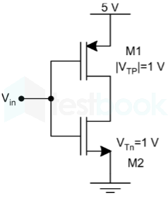
In the CMOS circuit shown, electron and hole mobilities are equal, and M1 and M2 are equally sized. The device M1 is in the linear region if

  1. ((a))

    Vin< 1.875 V

  2. ((b))

    1.875 V <Vin< 3.125 V

  3. ((c))

    Vin> 3.125 V

  4. ((d))

    0 <Vin< 5 V

Show Answer
Answer: ((a))

Vin< 1.875 V

M1 will be in linear region if Vout>Vin + VT

At the edge of the linear region Vout= Vin + VT

12Kn(VinVthn)2=Kp[(VDDVinVthp)(VDDVout)12(VDDVout)2] Or, 12Kn[VinVT]2=Kp[(VDDVinVT)(VDDVinVT)12(VDDVinVT)2] Or,   [VinVT]2=(VDDVinVT)2 Or,   (Vin1)2=(4Vin)2 Or,   Vin1=(4Vin) Or,   Vin=2.5\begin{array}{l} \frac{1}{2}{K_n}{\left( {{V_{in}} - {V_{thn}}} \right)^2} = {K_p}\left[ {\left( {{V_{DD}} - {V_{in}} - {V_{thp}}} \right)\left( {{V_{DD}} - {V_{out}}} \right) - \frac{1}{2}{{\left( {{V_{DD}} - {V_{out}}} \right)}^2}} \right]\ Or,\ \frac{1}{2}{K_n}{\left[ {{V_{in}} - {V_T}} \right]^2} = {K_p}\left[ {\left( {{V_{DD}} - {V_{in}} - {V_T}} \right)\left( {{V_{DD}} - {V_{in}} - {V_T}} \right) - \frac{1}{2}{{\left( {{V_{DD}} - {V_{in}} - {V_T}} \right)}^2}} \right]\ Or,\ \ \ {\left[ {{V_{in}} - {V_T}} \right]^2} = {\left( {{V_{DD}} - {V_{in}} - {V_T}} \right)^2}\ Or,\ \ \ {\left( {{V_{in}} - 1} \right)^2} = {\left( {4 - {V_{in}}} \right)^2}\ Or,\ \ \ {V_{in}} - 1 = \left( {4 - {V_{in}}} \right)\ Or,\ \ \ {V_{in}} = 2.5 \end{array}

So, for Vin< 2.5 the PMOS will be in a linear region so the correct option is (1)

48

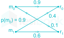
A two message communication system together with transition probabilities and priori probabilities is shown in the figure below. The optimum receiver used in such a system will contribute to a probability of error p(ε) equal to

  1. ((a))

    0.13

  2. ((b))

    0.1

  3. ((c))

    0.9

  4. ((d))

    0.87

Show Answer
Answer: ((b))

0.1

Concept:

The decision making algorithm used in optimum receiver is as follows:

If r0 is received, m0 is chosen only if:

p(r0 / m0) p(m0) > p(r0 / m1) p(m1)

And if r1 is received, m1 is chosen only if:

p(r1 / m1) p(m1) > p(r1 / m0) p(m0)

Analysis:

Given:

p(m0) = 0.9

p(m1) = 1 – 0.9 = 0.1

p(r0 / m0) = 0.9

p(r0 / m1) = 0.4

p(r1 / m0) = 0.1

p(r1 / m1) = 0.6

Now, test p(r0 / m0) p(m0) > p(r0 / m1) p(m1)

0.9 × 0.9 > 0.4 × 0.1 ; (true)

Decision: Choose m0 for received r0.

Test p(r1 / m1) p(m1) > p(r1 / m0) p(m0)

0.6 × 0.1 > 0.1 × 0.9 ; (not true)

Decision: Choose m0 for received r1.

In fact, in the given situation, the optimum receiver always decides in favor of m0 irrespective of whether r0 or r1 is received.

Now, the Probability of correct reception will be:

Pc = p(r0 / m0) p(m­0) + p(r1 / m0) p(m0)

= 0.9 × 0.9 + 0.1 × 0.9 = 0.9

BER = p(ε) = 1 - Pc

BER = 1 – 0.9 = 0.1

49

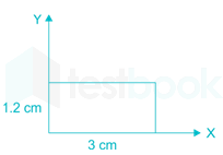
The magnetic field along the propagation direction inside a rectangular waveguide with the cross-section shown in the figure is

Hz=3cos(2.094×10²x)cos(2.618×10²y)cos(6.283×10¹⁰tβz)\rm {H_z} = 3\cos \left( {2.094 \times {{10}^2}x} \right)\cos \left( {2.618 \times {{10}^2}y} \right)\cos \left( {6.283 \times {{10}^{10}}t - \beta z} \right)

The phase velocity  of the wave inside waveguide satisfies:

  1. ((a))

    vp>c\rm {v_p} > c

  2. ((b))

    vp=c\rm {v_p} = c

  3. ((c))

    0<vp<c\rm 0 < {v_p} < c

  4. ((d))

    vp=0\rm {v_p} = 0

Show Answer
Answer: ((d))

vp=0\rm {v_p} = 0

We have the general equation of the z-axis directed magnetic field in a TE mode is given by

Hz=Hocos(mπax)cos(nπby)cos(6.283×10¹⁰tβz)\rm H_z=H_o\cos{\left(\frac{m\pi}{a}x\right)}\cos{\left(\frac{n\pi}{b}y\right)}\cos{\left(6.283\times 10^{10}t-\beta z\right)}

Comparing with 

Hz=3cos(2.094×10²x)cos(2.618×10²y)cos(6.283×10¹⁰tβz)\rm {H_z} = 3\cos \left( {2.094 \times {{10}^2}x} \right)\cos \left( {2.618 \times {{10}^2}y} \right)\cos \left( {6.283 \times {{10}^{10}}t - \beta z} \right)

we have

mπa=2.094×10²\rm \frac{m\pi}{a}=2.094\times 10^2

m=2.094×102×0.03π=2\rm \Rightarrow m=\frac{2.094\times 10^2\times 0.03}{\pi}=2

Similarly, nπa=2.618×10²\rm \frac{n\pi}{a}=2.618\times 10^2

n=2.618×102×0.012π=1\rm \Rightarrow n=\frac{2.618\times 10^2\times 0.012}{\pi}=1

Thus, the mode of propagation is TE21\rm {TE}_{21}

Now, cutoff frequency of this mode assuming air as the dielectric medium by default,

fc=c2(ma)2+(nb)2\rm f_c=\frac{c}{2}\sqrt{\left(\frac{m}{a}\right)^2+\left(\frac{n}{b}\right)^2}

fc=3×1082(20.03)2+(10.012)2\rm \Rightarrow f_c=\frac{3\times 10^8}{2}\sqrt{\left(\frac{2}{0.03}\right)^2+\left(\frac{1}{0.012}\right)^2}

fc=16 GHz\rm\Rightarrow f_c=16\ GHz

Now, operating frequency f=6.283×10102π=10 GHz\rm f=\frac{6.283\times 10^{10}}{2\pi}=10\ GHz

We see that operating frequency is less than the cut-off frequency. Hence there will be no propagation.

Thus, vp=0\rm v_p=0

50

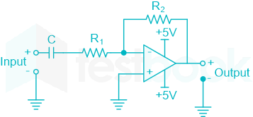
The circuit shown is a

  1. ((a))

    low pass filter with f3dB=1(R1+R2)C:rad/sf_{3dB}=\frac{1}{(R_1+R_2)C}:rad/s

  2. ((b))

    high pass filter with f3dB=1R1C:rad/sf_{3dB}=\frac{1}{R_1C}:rad/s

  3. ((c))

    low pass filter with f3dB=1R1C:rad/sf_{3dB}=\frac{1}{R_1C}:rad/s

  4. ((d))

    high pass filter with f3dB=1(R1+R2)C:rad/sf_{3dB}=\frac{1}{(R_1+R_2)C}:rad/s

Show Answer
Answer: ((b))

high pass filter with f3dB=1R1C:rad/sf_{3dB}=\frac{1}{R_1C}:rad/s

Active high pass filter:

The simplest HPF using an operational amplifier can be achieved by placing a capacitor in series with one of the resistors in the inverting amplifier circuit as shown.

Apply KCL at the inverting terminal node, we get

Vi0R1+1jωC=0V0R2\frac{{{V_i} - 0}}{{{R_1} + \frac{1}{{jω C}}}} = \frac{{0 - {V_0}}}{{{R_2}}}

V0Vi=R2R1+1jωC ⇒ \frac{{{V_0}}}{{{V_i}}} = \frac{{ - {R_2}}}{{{R_1} + \frac{1}{{jω C}}}}

Case 1:

If the frequency ω = 0 rad/sec

 V0Vi=R2R1+10=R2R1+=0 \Rightarrow \frac{{{V_0}}}{{{V_i}}} = \frac{{ - {R_2}}}{{{R_1} + \frac{1}{0}}} = \frac{{ - {R_2}}}{{{R_1} + ∞ }} = 0

So, for the frequency ω = 0, the output V0 =0

Case 2:

If the frequency ω = ∞ rad/sec

V0Vi=R2R1+1=R2R1+0=R2R1 \Rightarrow \frac{{{V_0}}}{{{V_i}}} = \frac{{ - {R_2}}}{{{R_1} + \frac{1}{∞ }}} = \frac{{ - {R_2}}}{{{R_1} + 0}} = \frac{{ - {R_2}}}{{{R_1}}}

So, for frequency ω = ∞ , the output V0=R2R1Vi{V_0} = \frac{{ - {R_2}}}{{{R_1}}}{V_i}

By, observing case 1 and case 2 we can say that the above circuit is allowing high frequencies but the lower frequencies are not allowed. Hence the above circuit is a high pass filter (HPF)

And the cutoff frequency or the breakpoint of the filter can be calculated very easily by working out of the frequency at which the reactance of the capacitor equals the resistance resistor to which the capacitor is connected in series.

So, Xc = R1

1ωc;C=R1 \Rightarrow \frac{1}{{{ω _c};C}} = {R_1}

ωc=1R1C \Rightarrow {ω _c} = \frac{1}{{{R_1}C}}

Where ωc is the cutoff frequency in rad/sec.

Hence the given circuit is a High pass filter with a cutoff frequency 1R1C\frac{1}{{{R_1}C}}.

51

Let y[n] denote the convolution of h[n] and g[n], where h[n] = (1/2)n u[n] and g[n] is a causal sequence. If y[0] = 1 and y[1] = ½, then g[1] equals

  1. ((a))

    0

  2. ((b))

    ½

  3. ((c))

    1

  4. ((d))

    3/2

Show Answer
Answer: ((a))

0

Convolution sum is defined as

\(y\left[ n \right] = h\left[ n \right]*g\left[ n \right] = \mathop \sum \limits_{k = - \infty }^\infty h\left[ k \right]g\left[ {n - k} \right]\)

For causal sequence,

y[n] = h[0] g[n] + h[1] g [n-1] + h[2] g[n-2] +….

For n = 0,

y[0] = h[0] g[0] + h[1] g[-1] +…..

= h [0] g[0]            (g[-1] = g[-2] =……..0)

y[0] = h[0] g[0]

For. n =1,  y [1] = h [0] g [1] + h [1] g [0] + h [2] g [-1] + ……

y [1] = h [0] g [1] + h [1] g [0] +....

12=g[1]+12g[0]\frac{1}{2} = g\left[ 1 \right] + \frac{1}{{2}}g\left[ 0 \right]

Now, g[0]=y[0]h[0]=11=1g\left[ 0 \right] = \frac{{y\left[ 0 \right]}}{{h\left[ 0 \right]}} = \frac{1}{1} = 1

g [1] = 0.5 - 0.5 = 0.

52

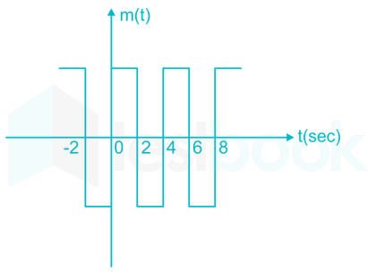
The signal m (t) as shown in figure below is applied both to a phase modulator (with kp as the phase constant) and a frequency modulator with (kf as the frequency constant) having the same carrier frequency(given m(t) maximum amplitude is 2). The ratio kp / kf (in rad/Hz) for the same maximum phase deviation is

  1. ((a))

  2. ((b))

    8 π

  3. ((c))

    π

  4. ((d))

Show Answer
Answer: ((a))

Given similar carrier frequency is used in both FM and PM modulation

Instantaneous phase in PM is given by θi(t) = ωct + kpm(t)

Instantaneous phase in FM is given by θi(t) = ωct + kf

Maximum phase deviation in PM is:

Δθ = Kp x Max (m(t)) 

= Kp x 2

While in FM, it will be:

kf x 2π x max (\( \mathop \smallint \limits_0^t m\left( t \right)dt\) )

= 2π kf x 4

Given phase deviation for both modulations are equal, we can write:

8 π kf = 2 Kp

kp / kf = 4π

53

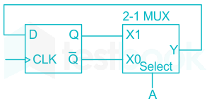
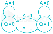
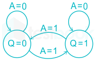
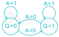
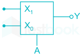
The state transition diagram for the logic circuit shown is

  1. ((a))

  2. ((b))

  3. ((c))

  4. ((d))

Show Answer
Answer: ((d))

Concept:

Output expression (Y) for 2 × 1 MUX is given as

Y = A̅ x0 + A x1          ---(1)

The next state (Qn + 1) of D flip flop is:

Qn + 1 = D           ---(2)

Analysis:

From given circuit:

D = Y, x1 = Q, x0 = Q̅

We know that

Y = A̅ x0 + A x1

From given data,

D = A̅ Q̅ + AQ

From eqn (2) θn+1 = A̅ Q̅ + A Q

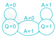
APresent state (Q)Next state (Qn+1)
00Q = 1
01Q = 0
10Q = 0
11Q = 1


So, the state transition diagram will be:

54

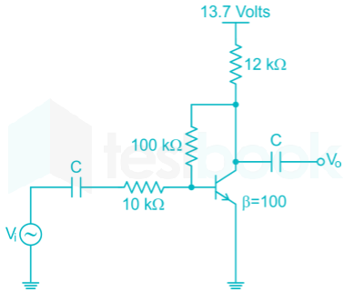
The voltage gain AV of the circuit shown below is

  1. ((a))

    |AV| ≈ 200

  2. ((b))

    |AV| ≈ 100

  3. ((c))

    |AV| ≈ 20

  4. ((d))

    |AV| ≈ 10

Show Answer
Answer: ((d))

|AV| ≈ 10

In ac analysis capacitor is short circuited and

VBEVin10K+VBEVout100K=0\frac{{{V_{BE}} - {V_{in}}}}{{10K}} + \frac{{{V_{BE}} - {V_{out}}}}{{100K}} = 0

VBE = 0.7 ≃ 0

Vin10=Vout100AV=VoutVin=10\therefore \frac{{ - {V_{in}}}}{{10}} = \frac{{{V_{out}}}}{{100}} \to \left| {{A_V}} \right| = \left| {\frac{{{V_{out}}}}{{{V_{in}}}}} \right| = 10

So option (4) is correct

55

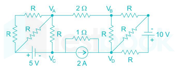
If VA – VB = 6 V then VC – VD is

  1. ((a))

    -5 V

  2. ((b))

    2 V

  3. ((c))

    3 V

  4. ((d))

    6 V

Show Answer
Answer: ((a))

-5 V

VA – VB = 6 V

So current in the branch will be

IAB = 6/2 = 3 A

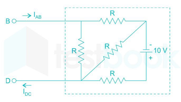
We can see, that the circuit is a one part circuit looking from terminal BD as shown below

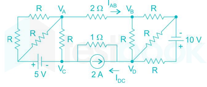
For a one port network current entering one terminal, equals the current leaving the second terminal. Thus the outgoing current from A to B will be equal to the incoming current from D to C as shown.

i.e. IDC = IAB = 3 A

The total current in the resistor 1 Ω will be

I1 = 2 + IDC

= 2 + 3 = 5 A

VCD = 1 × (-I1)

= -5 V

56

The maximum value of f(x) = x3 - 9x2 + 24x + 5 in the interval [1, 6] is

  1. ((a))

    21

  2. ((b))

    25

  3. ((c))

    41

  4. ((d))

    46

Show Answer
Answer: ((c))

41

f(x)=x39x2+24x+5;f\left( x \right) = {x^3} - 9{x^2} + 24x +5;

f(x)=3x218x+24{f^{'\left( x \right)}} = 3{x^2} - 18x + 24

f(x)=6x18{f^{''\left( x \right)}} = 6x - 18

To find maxima or minima

f(x)=0{f^{'\left( x \right)}} = 0

3x218x+24=03{x^2} - 18x + 24 = 0

x26x+8=0{x^2} - 6x + 8 = 0

x = 4 or x = 2

If x = 4

f'’(4) = 6

f'’(4) > 0

∴ minima may fall at 4 in the given domain

If x = 2

f'’(2) = -6

f'’(2) < 0

∴ maxima may fall at 2 in the given domain

Check the boundary condition along with x = 4 and x = 2

value of xf(x)
121
225
421
641


∴ The maximum value of given function is 41

57

Given that

A=[5320]:and:I=[1001]A=\left[ \begin{matrix} -5 && -3 \\ 2 && 0 \end{matrix} \right] :and:I=\left[ \begin{matrix} 1 && 0 \\ 0 && 1 \end{matrix} \right] the value of A3 is

  1. ((a))

    15A + 12I

  2. ((b))

    19A + 30I

  3. ((c))

    17A + 15I

  4. ((d))

    17A + 21I

Show Answer
Answer: ((b))

19A + 30I

Concept:

  • Cayley - Hamilton theorem states that every square matrix A satisfies its own characteristic equation. i.e. p(A) = 0.
  • The characteristic polynomial of a matrix A is defined as: p(λ) = |λI - A|.
  • Identity Matrix:

An identity matrix is a matrix in which the diagonal elements are 1 and all the other elements are 0.

A 3×3 identity matrix is I = \(\rm \begin{bmatrix} 1 & 0 & 0 \0 & 1 & 0 \0 & 0 & 1 \end{bmatrix}\).

Matrix Multiplication by an Identity matrix results in the same matrix.


Calculation:

Let us find the characteristic polynomial p(λ) of the given matrix A = [53 20]\rm \begin{bmatrix} -5 & -3\ 2 & 0 \end{bmatrix}.

p(λ) = |λI - A|

⇒ p(λ) = λ+53 2λ\rm \begin{vmatrix} \lambda+5 & 3\ -2 & \lambda \end{vmatrix}

⇒ p(λ) = (λ )(λ +5) + (2)(3)

⇒ p(λ) = λ2 + 5λ + 6 

According to the Cayley - Hamilton theorem, p(A) = 0.

⇒ A2 + 5A + 6I = 0  --------(1)

⇒ A2 = - 5A - 6I ---------(2)

By multiplying equation (1) with A, we get

A3 + 5A2 + 6A = 0

⇒ A3 = -5 A2 -6A = -5 (- 5A - 6I ) -6A = 19 A + 30I

Additional Information

Matrix Multiplication:

  • Multiplication is only possible when the number of columns of the first matrix is equal to the number of rows of the second matrix.
  • A m×n matrix multiplied by a n×p matrix results in a m×p matrix.
  • Matrices are multiplied by multiplying each element of a row of the first m×n matrix with the corresponding elements of all the columns of the second n×p matrix to obtain the first row of the product matrix with p columns, and so on for all the m rows of the first matrix.

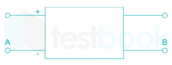
With 10 V dc connected at port A in the linear nonreciprocal two-port network shown below, the following were observed:

i)  1 Ω connected at port B draws a current of 3 A

ii)  2.5 Ω connected at port B draws a current of 2 A

58

With 10 V dc connected at port A, the current drawn by 7 Ω connected at port B is

  1. ((a))

    3/7 A

  2. ((b))

    5/7 A

  3. ((c))

    1 A

  4. ((d))

    9/7 A

Show Answer
Answer: ((c))

1 A

When 10 V is connected at port A the network is
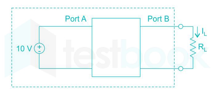
Now, we obtain Thevenin equivalent for the circuit seen at load terminal, let thevenin voltage is Vth ,10 V with 10 V applied at port A and thevenin resistance is Rth.
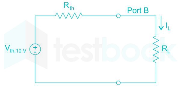
%MathType!Translator!2!1!LaTeX.tdl!LaTeX2.09andlater!%MathType!MTEF!2!1!+%feaagKart1ev2aqatCvAUfeBSjuyZL2yd9gzLbvyNv2CaerbuLwBLn%hiov2DGi1BTfMBaeXatLxBI9gBaerbd9wDYLwzYbItLDharqqtubsr%4rNCHbGeaGqiVu0Je9sqqrpepC0xbbL8F4rqqrFfpeea0xe9LqJc9%vqaqpepm0xbba9pwe9Q8fs0yqaqpepae9pg0FirpepeKkFr0xfrx%frxb9adbaqaaeGaciGaaiaabeqaamaabaabaaGcbaaeaaaaaaaaa8%qacaWGjbWdamaaBaaaleaapeGaamitaaWdaeqaaOWdbiabg2da9maa%laaapaqaa8qacaWGwbWdamaaBaaaleaapeGaamiDaiaadIgacaGGSa%GaaGymaiaaicdacaWGwbaapaqabaaakeaapeGaamOua8aadaWgaaWc%baWdbiaadshacaWGObaapaqabaGcpeGaey4kaSIaamOua8aadaWgaa%WcbaWdbiaadYeaa8aabeaaaaaaaa!45A9!IL=Vth,10VRth+RL%MathType!End!2!1!\% MathType!Translator!2!1!LaTeX.tdl!LaTeX 2.09 and later! \% MathType!MTEF!2!1!+- \% feaagKart1ev2aqatCvAUfeBSjuyZL2yd9gzLbvyNv2CaerbuLwBLn \% hiov2DGi1BTfMBaeXatLxBI9gBaerbd9wDYLwzYbItLDharqqtubsr \% 4rNCHbGeaGqiVu0Je9sqqrpepC0xbbL8F4rqqrFfpeea0xe9Lq-Jc9 \% vqaqpepm0xbba9pwe9Q8fs0-yqaqpepae9pg0FirpepeKkFr0xfr-x \% fr-xb9adbaqaaeGaciGaaiaabeqaamaabaabaaGcbaaeaaaaaaaaa8 \% qacaWGjbWdamaaBaaaleaapeGaamitaaWdaeqaaOWdbiabg2da9maa \% laaapaqaa8qacaWGwbWdamaaBaaaleaapeGaamiDaiaadIgacaGGSa \% GaaGymaiaaicdacaWGwbaapaqabaaakeaapeGaamOua8aadaWgaaWc \% baWdbiaadshacaWGObaapaqabaGcpeGaey4kaSIaamOua8aadaWgaa \% WcbaWdbiaadYeaa8aabeaaaaaaaa!45A9! {I_L} = \frac{{{V_{th,10V}}}}{{{R_{th}} + {R_L}}}\% MathType!End!2!1!

For RL = 1 Ω, IL = 3 A

%MathType!Translator!2!1!LaTeX.tdl!LaTeX2.09andlater!%MathType!MTEF!2!1!+%feaagKart1ev2aqatCvAUfeBSjuyZL2yd9gzLbvyNv2CaerbuLwBLn%hiov2DGi1BTfMBaeXatLxBI9gBaerbd9wDYLwzYbItLDharqqtubsr%4rNCHbGeaGqiVu0Je9sqqrpepC0xbbL8F4rqqrFfpeea0xe9LqJc9%vqaqpepm0xbba9pwe9Q8fs0yqaqpepae9pg0FirpepeKkFr0xfrx%frxb9adbaqaaeGaciGaaiaabeqaamaabaabaaGcbaaeaaaaaaaaa8%qacaaIZaGaeyypa0ZaaSaaa8aabaWdbiaadAfapaWaaSbaaSqaa8qa%caWG0bGaamiAaiaacYcacaaIXaGaaGimaiaadAfaa8aabeaaaOqaa8%qacaWGsbWdamaaBaaaleaapeGaamiDaiaadIgaa8aabeaak8qacqGH%RaWkcaaIXaaaaaaa!430C!3=Vth,10VRth+1%MathType!End!2!1!\% MathType!Translator!2!1!LaTeX.tdl!LaTeX 2.09 and later! \% MathType!MTEF!2!1!+- \% feaagKart1ev2aqatCvAUfeBSjuyZL2yd9gzLbvyNv2CaerbuLwBLn \% hiov2DGi1BTfMBaeXatLxBI9gBaerbd9wDYLwzYbItLDharqqtubsr \% 4rNCHbGeaGqiVu0Je9sqqrpepC0xbbL8F4rqqrFfpeea0xe9Lq-Jc9 \% vqaqpepm0xbba9pwe9Q8fs0-yqaqpepae9pg0FirpepeKkFr0xfr-x \% fr-xb9adbaqaaeGaciGaaiaabeqaamaabaabaaGcbaaeaaaaaaaaa8 \% qacaaIZaGaeyypa0ZaaSaaa8aabaWdbiaadAfapaWaaSbaaSqaa8qa \% caWG0bGaamiAaiaacYcacaaIXaGaaGimaiaadAfaa8aabeaaaOqaa8 \% qacaWGsbWdamaaBaaaleaapeGaamiDaiaadIgaa8aabeaak8qacqGH \% RaWkcaaIXaaaaaaa!430C! 3 = \frac{{{V_{th,10V}}}}{{{R_{th}} + 1}}\% MathType!End!2!1!

For RL = 2.5 Ω, IL = 2 A

%MathType!Translator!2!1!LaTeX.tdl!LaTeX2.09andlater!%MathType!MTEF!2!1!+%feaagKart1ev2aqatCvAUfeBSjuyZL2yd9gzLbvyNv2CaerbuLwBLn%hiov2DGi1BTfMBaeXatLxBI9gBaerbd9wDYLwzYbItLDharqqtubsr%4rNCHbGeaGqiVu0Je9sqqrpepC0xbbL8F4rqqrFfpeea0xe9LqJc9%vqaqpepm0xbba9pwe9Q8fs0yqaqpepae9pg0FirpepeKkFr0xfrx%frxb9adbaqaaeGaciGaaiaabeqaamaabaabaaGcbaaeaaaaaaaaa8%qacaaIYaGaeyypa0ZaaSaaa8aabaWdbiaadAfapaWaaSbaaSqaa8qa%caWG0bGaamiAaiaacYcacaaIXaGaaGimaiaadAfaa8aabeaaaOqaa8%qacaWGsbWdamaaBaaaleaapeGaamiDaiaadIgaa8aabeaak8qacqGH%RaWkcaaIYaGaaiOlaiaaiwdaaaaaaa!447D!2=Vth,10VRth+2.5%MathType!End!2!1!\% MathType!Translator!2!1!LaTeX.tdl!LaTeX 2.09 and later! \% MathType!MTEF!2!1!+- \% feaagKart1ev2aqatCvAUfeBSjuyZL2yd9gzLbvyNv2CaerbuLwBLn \% hiov2DGi1BTfMBaeXatLxBI9gBaerbd9wDYLwzYbItLDharqqtubsr \% 4rNCHbGeaGqiVu0Je9sqqrpepC0xbbL8F4rqqrFfpeea0xe9Lq-Jc9 \% vqaqpepm0xbba9pwe9Q8fs0-yqaqpepae9pg0FirpepeKkFr0xfr-x \% fr-xb9adbaqaaeGaciGaaiaabeqaamaabaabaaGcbaaeaaaaaaaaa8 \% qacaaIYaGaeyypa0ZaaSaaa8aabaWdbiaadAfapaWaaSbaaSqaa8qa \% caWG0bGaamiAaiaacYcacaaIXaGaaGimaiaadAfaa8aabeaaaOqaa8 \% qacaWGsbWdamaaBaaaleaapeGaamiDaiaadIgaa8aabeaak8qacqGH \% RaWkcaaIYaGaaiOlaiaaiwdaaaaaaa!447D! 2 = \frac{{{V_{th,10V}}}}{{{R_{th}} + 2.5}}\% MathType!End!2!1!

%MathType!Translator!2!1!LaTeX.tdl!LaTeX2.09andlater!%MathType!MTEF!2!1!+%feaagKart1ev2aqatCvAUfeBSjuyZL2yd9gzLbvyNv2CaerbuLwBLn%hiov2DGi1BTfMBaeXatLxBI9gBaerbd9wDYLwzYbItLDharqqtubsr%4rNCHbGeaGqiVu0Je9sqqrpepC0xbbL8F4rqqrFfpeea0xe9LqJc9%vqaqpepm0xbba9pwe9Q8fs0yqaqpepae9pg0FirpepeKkFr0xfrx%frxb9adbaqaaeGaciGaaiaabeqaamaabaabaaGcbaaeaaaaaaaaa8%qacqGHshI3daWcaaWdaeaapeGaaG4maaWdaeaapeGaaGOmaaaacqGH%9aqpdaWcaaWdaeaapeGaamOua8aadaWgaaWcbaWdbiaadshacaWGOb%aapaqabaGcpeGaey4kaSIaaGOmaiaac6cacaaI1aaapaqaa8qacaWG%sbWdamaaBaaaleaapeGaamiDaiaadIgaa8aabeaak8qacqGHRaWkca%aIXaaaaaaa!469D!32=Rth+2.5Rth+1%MathType!End!2!1!\% MathType!Translator!2!1!LaTeX.tdl!LaTeX 2.09 and later! \% MathType!MTEF!2!1!+- \% feaagKart1ev2aqatCvAUfeBSjuyZL2yd9gzLbvyNv2CaerbuLwBLn \% hiov2DGi1BTfMBaeXatLxBI9gBaerbd9wDYLwzYbItLDharqqtubsr \% 4rNCHbGeaGqiVu0Je9sqqrpepC0xbbL8F4rqqrFfpeea0xe9Lq-Jc9 \% vqaqpepm0xbba9pwe9Q8fs0-yqaqpepae9pg0FirpepeKkFr0xfr-x \% fr-xb9adbaqaaeGaciGaaiaabeqaamaabaabaaGcbaaeaaaaaaaaa8 \% qacqGHshI3daWcaaWdaeaapeGaaG4maaWdaeaapeGaaGOmaaaacqGH \% 9aqpdaWcaaWdaeaapeGaamOua8aadaWgaaWcbaWdbiaadshacaWGOb \% aapaqabaGcpeGaey4kaSIaaGOmaiaac6cacaaI1aaapaqaa8qacaWG \% sbWdamaaBaaaleaapeGaamiDaiaadIgaa8aabeaak8qacqGHRaWkca \% aIXaaaaaaa!469D! \Rightarrow \frac{3}{2} = \frac{{{R_{th}} + 2.5}}{{{R_{th}} + 1}}\% MathType!End!2!1!

⇒ Rth = 2 Ω

Vth,10 V = 3 (2 + 1) = 9 V

Note than it is a nonreciprocal two port network thevenin voltage seen at port B depends on the voltage connected at port A. therefore we took subscript Vth,10 V . This is thevenin voltage only when 10 V source is connected at input port A. If the voltage connected to port A is different, then thevenin voltage will be different. However, Thevenin’s resistance remains same. Now, the circuit is

For RL = 7 Ω 

%MathType!Translator!2!1!LaTeX.tdl!LaTeX2.09andlater!%MathType!MTEF!2!1!+%feaagKart1ev2aqatCvAUfeBSjuyZL2yd9gzLbvyNv2CaerbuLwBLn%hiov2DGi1BTfMBaeXatLxBI9gBaerbd9wDYLwzYbItLDharqqtubsr%4rNCHbGeaGqiVu0Je9sqqrpepC0xbbL8F4rqqrFfpeea0xe9LqJc9%vqaqpepm0xbba9pwe9Q8fs0yqaqpepae9pg0FirpepeKkFr0xfrx%frxb9adbaqaaeGaciGaaiaabeqaamaabaabaaGcbaaeaaaaaaaaa8%qacaWGjbWdamaaBaaaleaapeGaamitaaWdaeqaaOWdbiabg2da9maa%laaapaqaa8qacaWGwbWdamaaBaaaleaapeGaamiDaiaadIgacaGGSa%GaaGymaiaaicdacaWGwbaapaqabaaakeaapeGaaGOmaiabgUcaRiaa%dkfapaWaaSbaaSqaa8qacaWGmbaapaqabaaaaOWdbiabg2da9maala%aapaqaa8qacaaI5aaapaqaa8qacaaIYaGaey4kaSIaaG4naaaacqGH%9aqpcaaIXaGaaiiOaiaadgeaaaa!4B6F!IL=Vth,10V2+RL=92+7=1;A%MathType!End!2!1!\% MathType!Translator!2!1!LaTeX.tdl!LaTeX 2.09 and later! \% MathType!MTEF!2!1!+- \% feaagKart1ev2aqatCvAUfeBSjuyZL2yd9gzLbvyNv2CaerbuLwBLn \% hiov2DGi1BTfMBaeXatLxBI9gBaerbd9wDYLwzYbItLDharqqtubsr \% 4rNCHbGeaGqiVu0Je9sqqrpepC0xbbL8F4rqqrFfpeea0xe9Lq-Jc9 \% vqaqpepm0xbba9pwe9Q8fs0-yqaqpepae9pg0FirpepeKkFr0xfr-x \% fr-xb9adbaqaaeGaciGaaiaabeqaamaabaabaaGcbaaeaaaaaaaaa8 \% qacaWGjbWdamaaBaaaleaapeGaamitaaWdaeqaaOWdbiabg2da9maa \% laaapaqaa8qacaWGwbWdamaaBaaaleaapeGaamiDaiaadIgacaGGSa \% GaaGymaiaaicdacaWGwbaapaqabaaakeaapeGaaGOmaiabgUcaRiaa \% dkfapaWaaSbaaSqaa8qacaWGmbaapaqabaaaaOWdbiabg2da9maala \% aapaqaa8qacaaI5aaapaqaa8qacaaIYaGaey4kaSIaaG4naaaacqGH \% 9aqpcaaIXaGaaiiOaiaadgeaaaa!4B6F! {I_L} = \frac{{{V_{th,10V}}}}{{2 + {R_L}}} = \frac{9}{{2 + 7}} = 1;A\% MathType!End!2!1!
59

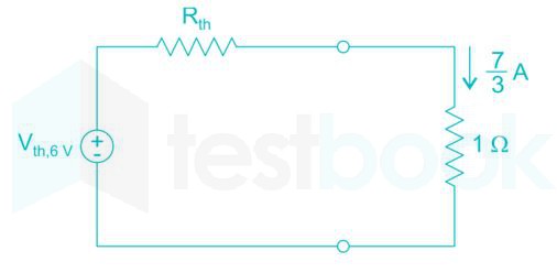
With 6 V dc connected at port A, 1 Ω connected at port B draws 7/3 A. If 8 V dc is connected to port A, the open circuit voltage at port B is

  1. ((a))

    6 V

  2. ((b))

    7 V

  3. ((c))

    8 V

  4. ((d))

    9 V

Show Answer
Answer: ((c))

8 V

Now, when 6 V connected at port A let thevenin voltage seen at port B is Vth,6 V . Here RL = 1 Ω and IL = 7/3 A

%MathType!Translator!2!1!LaTeX.tdl!LaTeX2.09andlater!%MathType!MTEF!2!1!+%feaagKart1ev2aqatCvAUfeBSjuyZL2yd9gzLbvyNv2CaerbuLwBLn%hiov2DGi1BTfMBaeXatLxBI9gBaerbd9wDYLwzYbItLDharqqtubsr%4rNCHbGeaGqiVu0Je9sqqrpepC0xbbL8F4rqqrFfpeea0xe9LqJc9%vqaqpepm0xbba9pwe9Q8fs0yqaqpepae9pg0FirpepeKkFr0xfrx%frxb9adbaqaaeGaciGaaiaabeqaamaabaabaaGcbaaeaaaaaaaaa8%qacaWGwbWdamaaBaaaleaapeGaamiDaiaadIgacaGGSaGaaGOnaiaa%dAfaa8aabeaak8qacqGH9aqpcaWGsbWdamaaBaaaleaapeGaamiDai%aadIgaa8aabeaak8qacqGHxdaTdaWcaaWdaeaapeGaaG4naaWdaeaa%peGaaG4maaaacqGHRaWkcaaIXaGaey41aq7aaSaaa8aabaWdbiaaiE%daa8aabaWdbiaaiodaaaaaaa!4931!Vth,6V=Rth×73+1×73%MathType!End!2!1!\% MathType!Translator!2!1!LaTeX.tdl!LaTeX 2.09 and later! \% MathType!MTEF!2!1!+- \% feaagKart1ev2aqatCvAUfeBSjuyZL2yd9gzLbvyNv2CaerbuLwBLn \% hiov2DGi1BTfMBaeXatLxBI9gBaerbd9wDYLwzYbItLDharqqtubsr \% 4rNCHbGeaGqiVu0Je9sqqrpepC0xbbL8F4rqqrFfpeea0xe9Lq-Jc9 \% vqaqpepm0xbba9pwe9Q8fs0-yqaqpepae9pg0FirpepeKkFr0xfr-x \% fr-xb9adbaqaaeGaciGaaiaabeqaamaabaabaaGcbaaeaaaaaaaaa8 \% qacaWGwbWdamaaBaaaleaapeGaamiDaiaadIgacaGGSaGaaGOnaiaa \% dAfaa8aabeaak8qacqGH9aqpcaWGsbWdamaaBaaaleaapeGaamiDai \% aadIgaa8aabeaak8qacqGHxdaTdaWcaaWdaeaapeGaaG4naaWdaeaa \% peGaaG4maaaacqGHRaWkcaaIXaGaey41aq7aaSaaa8aabaWdbiaaiE \% daa8aabaWdbiaaiodaaaaaaa!4931! {V_{th,6V}} = {R_{th}} \times \frac{7}{3} + 1 \times \frac{7}{3}\% MathType!End!2!1!
%MathType!Translator!2!1!LaTeX.tdl!LaTeX2.09andlater!%MathType!MTEF!2!1!+%feaagKart1ev2aqatCvAUfeBSjuyZL2yd9gzLbvyNv2CaerbuLwBLn%hiov2DGi1BTfMBaeXatLxBI9gBaerbd9wDYLwzYbItLDharqqtubsr%4rNCHbGeaGqiVu0Je9sqqrpepC0xbbL8F4rqqrFfpeea0xe9LqJc9%vqaqpepm0xbba9pwe9Q8fs0yqaqpepae9pg0FirpepeKkFr0xfrx%frxb9adbaqaaeGaciGaaiaabeqaamaabaabaaGcbaaeaaaaaaaaa8%qacqGH9aqpcaaIYaGaey41aq7aaSaaa8aabaWdbiaaiEdaa8aabaWd%biaaiodaaaGaey4kaSYaaSaaa8aabaWdbiaaiEdaa8aabaWdbiaaio%daaaGaeyypa0JaaG4naiaadAfaaaa!410C!=2×73+73=7V%MathType!End!2!1!\% MathType!Translator!2!1!LaTeX.tdl!LaTeX 2.09 and later! \% MathType!MTEF!2!1!+- \% feaagKart1ev2aqatCvAUfeBSjuyZL2yd9gzLbvyNv2CaerbuLwBLn \% hiov2DGi1BTfMBaeXatLxBI9gBaerbd9wDYLwzYbItLDharqqtubsr \% 4rNCHbGeaGqiVu0Je9sqqrpepC0xbbL8F4rqqrFfpeea0xe9Lq-Jc9 \% vqaqpepm0xbba9pwe9Q8fs0-yqaqpepae9pg0FirpepeKkFr0xfr-x \% fr-xb9adbaqaaeGaciGaaiaabeqaamaabaabaaGcbaaeaaaaaaaaa8 \% qacqGH9aqpcaaIYaGaey41aq7aaSaaa8aabaWdbiaaiEdaa8aabaWd \% biaaiodaaaGaey4kaSYaaSaaa8aabaWdbiaaiEdaa8aabaWdbiaaio \% daaaGaeyypa0JaaG4naiaadAfaaaa!410C! = 2 \times \frac{7}{3} + \frac{7}{3} = 7V\% MathType!End!2!1!
This is a linear network, so Vth­ at port B can be written as

Vth = V1 α + β

Where V1 is the input applied at port A.

We have V1 = 10 V, Vth,10 V = 9 V

9 = 10 α + β

when V1 = 6 V, Vth,6 V = 9 V

7 = 6 α + β

⇒ α = 0.5, β = 4

Thus, with any voltage V1 applied at port A, thevenin voltage or open circuit voltage at port B will be

%MathType!Translator!2!1!LaTeX.tdl!LaTeX2.09andlater!%MathType!MTEF!2!1!+%feaagKart1ev2aqatCvAUfeBSjuyZL2yd9gzLbvyNv2CaerbuLwBLn%hiov2DGi1BTfMBaeXatLxBI9gBaerbd9wDYLwzYbItLDharqqtubsr%4rNCHbGeaGqiVu0Je9sqqrpepC0xbbL8F4rqqrFfpeea0xe9LqJc9%vqaqpepm0xbba9pwe9Q8fs0yqaqpepae9pg0FirpepeKkFr0xfrx%frxb9adbaqaaeGaciGaaiaabeqaamaabaabaaGcbaaeaaaaaaaaa8%qacaWGwbWdamaaBaaaleaapeGaamiDaiaadIgacaGGSaGaamOva8aa%daWgaaadbaWdbiaaigdaa8aabeaaaSqabaGcpeGaeyypa0JaaGimai%aac6cacaaI1aGaaiiOaiaadAfapaWaaSbaaSqaa8qacaaIXaaapaqa%baGcpeGaey4kaSIaaGinaaaa!43E8!Vth,V1=0.5;V1+4%MathType!End!2!1!\% MathType!Translator!2!1!LaTeX.tdl!LaTeX 2.09 and later! \% MathType!MTEF!2!1!+- \% feaagKart1ev2aqatCvAUfeBSjuyZL2yd9gzLbvyNv2CaerbuLwBLn \% hiov2DGi1BTfMBaeXatLxBI9gBaerbd9wDYLwzYbItLDharqqtubsr \% 4rNCHbGeaGqiVu0Je9sqqrpepC0xbbL8F4rqqrFfpeea0xe9Lq-Jc9 \% vqaqpepm0xbba9pwe9Q8fs0-yqaqpepae9pg0FirpepeKkFr0xfr-x \% fr-xb9adbaqaaeGaciGaaiaabeqaamaabaabaaGcbaaeaaaaaaaaa8 \% qacaWGwbWdamaaBaaaleaapeGaamiDaiaadIgacaGGSaGaamOva8aa \% daWgaaadbaWdbiaaigdaa8aabeaaaSqabaGcpeGaeyypa0JaaGimai \% aac6cacaaI1aGaaiiOaiaadAfapaWaaSbaaSqaa8qacaaIXaaapaqa \% baGcpeGaey4kaSIaaGinaaaa!43E8! {V_{th,{V_1}}} = 0.5;{V_1} + 4\% MathType!End!2!1!
V1 = 8 V

Vth,8 V = (0.5 × 8) + 4 = 8 = open circuit voltage

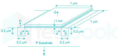
In the three dimensional view of a silicon n-channel MOS transistor shown below, d = 20 nm. The transistor is of width 1 μm. The depletion width formed at every p-n junction is 10 nm. The relative permittivities of SiO2 and Si, respectively, are 3.9 and 11.7, and ε0 = 8.9 × 10⁻¹² F/m.

60

The gate-source overlap capacitance is approximately

  1. ((a))

    0.7 fF

  2. ((b))

    0.7 pF

  3. ((c))

    0.35 fF

  4. ((d))

    0.24 pF

Show Answer
Answer: ((a))

0.7 fF

Gate to source overlap capacitance is approximately

Cgs;ov=ϵsio2AD{C_{gs;ov}} = \frac{{{\epsilon_{si{o_2}}}A}}{D}    (Where, A = d x width)

=3.9×8.9×1012×(1μm×20nm)1nm = \frac{{3.9 \times 8.9 \times {{10}^{ - 12}} \times \left( {1\mu m \times 20nm} \right)}}{{1nm}}

=;0.7;×;1015 = ;0.7; \times ;{10^{-15}}

=;0.7;fF = ;0.7;fF

61

The source–body junction capacitance is approximately.

  1. ((a))

    2 fF

  2. ((b))

    7 fF

  3. ((c))

    2 pF

  4. ((d))

    7 pF

Show Answer
Answer: ((b))

7 fF

The source touches the body on all the five side except the top face. Hence, the total side wall area in contact with body is

A=(0.2μm×1μm)+(0.2μm×1μm)+(0.2μm×1μm)+2(0.2μm×0.2μm)\rm A = (0.2 μm × 1μm) + (0.2 μm × 1μm) + (0.2 μm × 1μm) + 2 (0.2 μm ×0.2 μm)

=0.68×10¹²m2\rm = 0.68 × 10^{–12} m^2

Now,

CSB=ϵsiAW\rm {C_{SB}} = \frac{{{\epsilon_{si}}A}}{W}

Where, W = width of the depletion region = 10nm

CSB=11.7×8.9×1012×0.68×101210×109\rm \therefore {C_{SB}} = \frac{{11.7 × 8.9 × {{10}^{ - 12}} × 0.68 × {{10}^{ - 12}}}}{{10 × {{10}^{ - 9}}}}

=;70.8;×;1014 = ;70.8; × ;{10^{-14}}

 = 7 × 10-15 F

Sine 10-15 is called as Femto (f), we can write:

CSB=;7;fFC_{SB} = ;7;fF

An infinitely long uniform solid wire of radius a carries a uniform dc current of density J\vec J .

62

The magnetic field at a distance r from the center of the wire is proportional to

  1. ((a))

    r for r < a and 1/r2 for r > a

  2. ((b))

    0 for r < a and 1/r for r > a

  3. ((c))

    r for r < a and 1/r for r > a

  4. ((d))

    0 for r < a and 1/r2 for r > a

Show Answer
Answer: ((c))

r for r < a and 1/r for r > a

Magnetic flux density at a distance ‘r’ from the wire is

B=μo.I2πr\left| {\vec B} \right| = \frac{{{\mu _o}.I}}{{2\pi r}}

For r<a,;I=J.πr2r < a,;I = J.\pi {r^2}.......(uniform current density)

B=μo.Jπa22πr=μoJa22.1rB1r \Rightarrow \left| {\vec B} \right| = \frac{{{\mu _o}.J\pi {a^2}}}{{2\pi r}} = \frac{{{\mu _o}J{a^2}}}{2}.\frac{1}{r} \Rightarrow \left| {\vec B} \right| \propto \frac{1}{r}

for r > a

63

A hole of radius b (b < a) is now drilled along the length of the wire at a distance d from  the center of the wire as shown below.

The magnetic field inside the hole is

  1. ((a))

    uniform and depends only on d

  2. ((b))

    uniform and depends only on b

  3. ((c))

    uniform and depends on both b and d

  4. ((d))

    non uniform

Show Answer
Answer: ((a))

uniform and depends only on d

At all points in the hole, magnetic field depends on current enclosed, which will depend on surface area of wire conducting the current. This can be calculated by simple geometry which depends on only on the distance vector between radius of wire and radius of hole.

The transfer function of a compensator is given as

Gc(S)=s+as+bG_c(S)=\frac{s+a}{s+b}

64

Gc(s) is a lead compensator if

  1. ((a))

    a = 1, b = 2

  2. ((b))

    a = 3, b = 2

  3. ((c))

    a = -3, b = -1

  4. ((d))

    a = 3, b = 1

Show Answer
Answer: ((a))

a = 1, b = 2

Concept:

The general expression for a lead compensator is;

G(s)=(α)(1+Ts)(1+αTs)G\left( s \right)=\frac{\left( \alpha \right)\left( 1+Ts \right)}{\left( 1+\alpha Ts \right)}

And for a lead compensator α < 1

Analysis:

Given lead compensator expression is;

Gc(s)=k(s+a)(s+b){{G}_{c}}\left( s \right)=\frac{k\left( s+a \right)}{\left( s+b \right)}

On comparing it with the standard expression we get;

T=1a ,  αT=1bT=\frac{1}{a}~,~~\alpha T=\frac{1}{b}

αa=1bα=ab\Rightarrow \frac{\alpha }{a}=\frac{1}{b}\Rightarrow \alpha =\frac{a}{b}

⇒ a < b

Only two options are valid as per the above condition, options 1 and 3

But we can't go with option 3, because for lead compensator zero is near to the origin compared to pole.

Hence, a = 1, b = 2

65

The phase of the above lead compensator is maximum at

  1. ((a))

    √2 rad/s

  2. ((b))

    √3 rad/s

  3. ((c))

    √6 rad/s

  4. ((d))

    1/√3 rad/s

Show Answer
Answer: ((a))

√2 rad/s

Maximum phase at frequency

 ωm=1Tα\rm {\omega _m} = \frac{1}{{T\sqrt \alpha }}   (for Gc(s)=1+sT1+αsT;α<1)\rm \left( {{\rm{for}}\ {G_c}\left( s \right) = \frac{{1 + sT}}{{1 + \alpha sT}};\alpha < 1} \right)

Gc(s)=s+1s+2=1+s1+0.5s\rm {G_c}\left( s \right) = \frac{{s + 1}}{{s + 2}} = \frac{{1 + s}}{{1 + 0.5s}}

Comparing T=1,αT=0.5\rm T = 1, αT = 0.5

α=0.5\rm α = 0.5

ωm=110.5=2 rad/sec\rm {\omega _m} = \frac{1}{{1\sqrt {0.5} }} = \sqrt 2\ {\rm{rad}}/{\rm{sec}}

Attempt this paper under real exam conditions

Timed interface, section switching, instant scoring, and question-by-question analytics — free.

Start Timed Attempt