Official Paper

GATE EC 2011 Official Paper (Previous Year Paper)

65 questions · 180 minutes · with answers · free

General Aptitude (10 questions)

1

The question below consists of a pair of related words followed by four pairs of words. Select the pair that best expresses the relation in the original pair:

Gladiator ∶ Arena

  1. ((a))

    Dancer ∶ Stage

  2. ((b))

    Commuter ∶ Train

  3. ((c))

    Teacher ∶ Classroom

  4. ((d))

    Lawyer ∶ Courtroom

Show Answer
Answer: ((d))

Lawyer ∶ Courtroom

The Gladiator fights in the Arena to win battles. 

Similarly; 

A lawyer fights in the court to win cases.

Hence, "Lawyer ∶ Courtroom" is the correct answer.

Additional Information1) Dancer ∶ Stage →

Dancer dances on the Stage.

2) Commuter ∶ Train →

Commuter travels in train or Traveller travels in Train. (commuter means traveler)

3) Teacher ∶ Classroom →

Teacher teaches in Classroom.

2

There are two candidates P and Q in an election. During the campaign, 40% of the voters promised to vote for P, and rest for Q. However, on the day of election 15% of the voters went back on their promise to vote for P and instead voted for Q. 25% of the voters went back on their promise to vote for Q and instead voted for P. Suppose, P lost by 2 votes, then what was the total number of voters? 

  1. ((a))

    100

  2. ((b))

    110

  3. ((c))

    90

  4. ((d))

    95

Show Answer
Answer: ((a))

100

Explanation:

Let; Total number of voters = X

Number of voters P was supposed to get = 0.4X

Number of voters Q was supposed to get =  0.6X

According to the given information;

Number of voters P got = 85/100 (0.4X) + 25/100 (0.6X)

Number of voters Q got = 75/100 (0.6X) + 15/100 (0.4X)

Q - P = 2

⇒ 75/100 (0.6X) + 15/100 (0.4X) - 85/100 (0.4X) - 25/100 (0.6X) = 2

⇒ 50/100 (0.6X) - 70/100 (0.4X) = 2

⇒ 30X - 28X = 200

⇒ 2X = 200

⇒ X = 100

Hence, total number of voters are 100.

3

Choose the most appropriate word from the options given below to complete the following sentence:

It was her view that the country's problems had been _______ by foreign technocrats, so that to invite them to come back would be counter-productive.

  1. ((a))

    identified

  2. ((b))

    ascertained

  3. ((c))

    exacerbated

  4. ((d))

    analysed

Show Answer
Answer: ((c))

exacerbated

The correct answer is 'exacerbated'.

Key Points

  • Let's explore options;
  • identified: establish or indicate who or what (someone or something) is.
  • Example: Even the smallest baby can identify its mother by her voice.
  • ascertained: find (something) out for certain; make sure of.
  • Example: The police have so far been unable to ascertain the cause of the explosion.
  • exacerbated: make (a problem, bad situation, or negative feeling) worse.
  • Example: This attack will exacerbate the already tense relations between the two communities.
  • analysed: discover or reveal (something) through detailed examination.
  • Example: Researchers analysed the purchases of 6,300 households.
  • Thus, from above, we can conclude that 'exacerbated' will be used in the blank because of the keyword 'counterproductive' which suggests technocrats must have done something to make the situation worse.
  • Therefore, the correct answer is option 3.
4

Choose the word from the options given below that is most nearly opposite in meaning to the given word:

Frequency

  1. ((a))

    periodicity

  2. ((b))

    rarity

  3. ((c))

    gradualness

  4. ((d))

    persistency

Show Answer
Answer: ((b))

rarity

The correct answer is 'rarity'.

Key Points

  • Frequency: the fact of being frequent or happening often.
  • Example: Complaints about the frequency of buses rose in the last year.
  • Rarity: the state or quality of being rare.
  • Example: Snow in Florida is a rarity.
  • Thus, the correct answer is option 2.

Additional Information

  • Let's explore the other options:
  • periodicity: the quality or character of being periodic; the tendency to recur at intervals.
  • gradualness: Occurring or developing slowly or by small increments
  • persistency: the continued or prolonged existence of something.
5

Choose the most appropriate word from the options given below to complete the following sentence:

Under ethical guidelines recently adopted by the Indian Medical Association, human genes are to be manipulated only to correct diseases for which _______ treatments are unsatisfactory.

  1. ((a))

    similar

  2. ((b))

    most

  3. ((c))

    uncommon

  4. ((d))

    available

Show Answer
Answer: ((d))

available

The correct answer is 'available'.

Key Points

  • Let's explore options:
  • similar: a person or thing similar to another.
  • Example: My father and I have similar views on politics.
  • most: a large number of.
  • Example: What's the most you've ever won at poker?
  • uncommon: out of the ordinary; unusual.
  • Example: Accidents due to failure of safety equipment are uncommon nowadays.
  • available: able to be used or obtained.
  • Example: Is this dress available in a larger size?
  • Thus, from above, we can conclude that the correct answer is option 4.

Therefore, the correct sentence is: Under ethical guidelines recently adopted by the Indian Medical Association, human genes are to be manipulated only to correct diseases for which available treatments are unsatisfactory.

6

The horse has played a little known but very important role in the field of medicine. Horses were injected with toxins of diseases until their blood built up immunities. Then a serum was made from their blood. Serums to fight with diphtheria and tetanus were developed this way.

It can be inferred from the passage, that horses were

  1. ((a))

    given immunity to diseases

  2. ((b))

    generally quite immune to diseases

  3. ((c))

    given medicines to fight toxins

  4. ((d))

    given diphtheria and tetanus serums

Show Answer
Answer: ((b))

generally quite immune to diseases

The correct answer is 'generally quite immune to diseases'.

Key Points

  • Let's refer to the following lines of the passage:
  • Horses were injected with toxins of diseases until their blood built up immunities. Then a serum was made from their blood.
  • From above it can be inferred that the horses are quite immune to diseases as they themselves build the immunities in their blood to fight the toxins.
  • Thus, the correct answer is option 2.
7

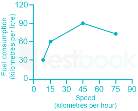
The fuel consumed by a motorcycle during a journey while traveling at various speeds a indicated in the graph below.

The distances covered during four laps of the journey are listed in the table below:

LapDistance
(kilometres)
Average speed
(kilometres per hour)
P1515
Q7545
R4075
S1010
<br>

From the given data, we can conclude that the fuel consumed per kilometre was least during the lap

  1. ((a))

    P

  2. ((b))

    Q

  3. ((c))

    R

  4. ((d))

    S

Show Answer
Answer: ((b))

Q

Calculation:

Consumption (km/liter) means distance covered by the car in 1 liter of fuel

⇒ Fuel consumption per liter = 1Consumption (km/liter)\frac{1}{Consumption\ (km/liter)}

PQRS
Distance15754010
Speed15457510
Consumption (km/liter)60907530
Fuel consumption per km160\frac{1}{60} = 0.016190\frac{1}{90} = 0.011​​175\frac{1}{75}​ = 0.013130\frac{1}{30} = 0.033


From the above table, fuel consumption per km was least during the lap Q.

∴ The correct answer is Q.

8

Three friends, R, S and T shared toffee from a bowl. R took 1/3rd of the toffees, but returned four to the bowl. S took 1/4th of what was left but returned three toffees to the bowl. T took half of the remainder but returned two back into the bowl. If the bowl had 17 toffees left, how many toffees were originally there in the bowl?

  1. ((a))

    38

  2. ((b))

    31

  3. ((c))

    48

  4. ((d))

    41

Show Answer
Answer: ((c))

48

Let the total number of toffees in bowl be x

R took 1/3 of toffees and returned 4 to the bowl

∴ Number of toffees with R = x/3 - 4

Remaining of toffees in bowl = 2x/3 + 4

Number of toffees with S=14[23x+4]3S = \frac{1}{4}[\frac{2}{3}x+4]-3

Remaining toffees in bowl = 34[23x+4]+3 \frac{3}{4}[\frac{2}{3}x+4]+3

Number of toffees with T = 12[34(23x+4)+3]2\frac{1}{2}[\frac{3}{4}(\frac{2}{3}x+4)+3]-2

Remaining toffees in bowl = 12[34(23x+4)+3]+2\frac{1}{2}[\frac{3}{4}(\frac{2}{3}x+4)+3]+2

Given: 12[34(23x+4)+3]+2=17\frac{1}{2}[\frac{3}{4}(\frac{2}{3}x+4)+3]+2=17

⇒ x = 48

∴ There were 48 toffees in the bowl.

9

Given that f(y) = |y|/y, and q is any non-zero real number, the value of |f(q) - f(-q)| is 

  1. ((a))

    0

  2. ((b))

    -1

  3. ((c))

    1

  4. ((d))

    2

Show Answer
Answer: ((d))

2

Given

f(y) = |y|/y

f(q) = |q|/q      ----(1)

f(-q) = |-q|/(-q)

f(-q) = |q|/-(q) 

f(-q) = - |q|/q     ----(2)

From (1) and (2)

|f(q) - f(-q)| = 2|q|/q = 2

∴ The correct answer is 2.

10

The sum of n terms of the series 4 + 44 + 444 + ... is

  1. ((a))

    (4/81) [10n+1 - 9n - 1]

  2. ((b))

    (4/81) [10n-1 - 9n - 1]

  3. ((c))

    (4/81) [10n+1 - 9n - 10]

  4. ((d))

    (4/81) [10n - 9n - 10]

Show Answer
Answer: ((c))

(4/81) [10n+1 - 9n - 10]

Let S = 4(1 + 11 + 111 + ...) = 49(9+99+999+...)\frac{4}{9}(9 + 99 + 999 + ...)

49[(101)+(1021)+(1031)+...]\Rightarrow\frac{4}{9}[(10 - 1) + (10^2-1)+(10^3-1)+...]

49[(10+102+...10n)n]=49[10(10n1)9n]\Rightarrow\frac{4}{9}[(10 + 10^2 +...10^n)-n]=\frac{4}{9}[10\frac{(10^n-1)}{9}-n]

481[10n+19n10]\Rightarrow \frac{4}{81}[10^{n+1}-9n-10]

Electronics and Communication Engineering (55 questions)

11

Consider the following statements regarding the complex Poynting vector P\vec P  for the power radiated by a point source in an infinite homogeneous and lossless medium. Re(P)Re\left( {\vec P} \right) denotes the real part of  P\vec P , S denotes a spherical surface whose centre is at the point source, and n^\hat ndenotes the unit surface normal on S. which of the following statements is TRUE ?

  1. ((a))

    Re(P)Re\left( {\vec P} \right) remains constant at any radian distance from the source

  2. ((b))

    Re(P)Re\left( {\vec P} \right) increases with increasing radial distance from the source

  3. ((c))

    sRe(P)n^ ds∯_s Re\left( {\vec P } \right)\cdot \hat n\ d\vec s remains constant at any radial distance from the source

  4. ((d))

    sRe(P)n^ ds∯_s Re\left( {\vec P } \right)\cdot \hat n\ d\vec s decreases with increasing radial distance from the source

Show Answer
Answer: ((d))

sRe(P)n^ ds∯_s Re\left( {\vec P } \right)\cdot \hat n\ d\vec s decreases with increasing radial distance from the source

Poynting vector:

It states that the cross product of electric field vector (E) and magnetic field vector (H) at any point is a measure of the rate of flow of electromagnetic energy per unit area at that point that is 

S=E×H \vec S = \vec E \times \vec H

S = Poynting vector

E = Electric field and

H = Magnetic field

The Poynting vector describes the magnitude and direction of the flow of energy in electromagnetic waves per unit volume.

sRe(P)n^ ds∯_s Re\left( {\vec P } \right)\cdot \hat n\ d\vec s,  gives average power and it decreases with the increasing radial distance from the source.

12

A transmission line of characteristic impedance 50 Ω is terminated by a 50 Ω load. When excited by a sinusoidal voltage source at 10 GHz, the phase difference between two points spaced 2 mm apart on the line is found to be π/4 radians. The phase velocity of the wave along the line is

  1. ((a))

    0.8 × 10⁸ m/s

  2. ((b))

    1.2 × 10⁸ m/s

  3. ((c))

    1.6 × 10⁸ m/s

  4. ((d))

    3 × 10⁸ m/s

Show Answer
Answer: ((c))

1.6 × 10⁸ m/s

Concept:

Phase velocity: 

v = f.λ 

Calculation:

Phase difference for the distance,

 2mm=π42mm = \frac{\pi }{4}

Distance for phase difference,

 2π=2mm×(8)2\pi = 2mm \times \left( 8 \right) 

;λ;=;16mm\Rightarrow ;λ ; = ;16mm

Excitation frequency f = 10 GHz

Phase velocity,

 v=f.;λ=(10×109)×(16×;103)=1.6×10⁸ m/sv = f.;λ = \left( {10 \times {{10}^9}} \right) \times \left( {16 \times ;{{10}^{ - 3}}} \right) = 1.6 \times {10^8}~m/s

13

An analog signal is bandlimited to 4 KHz, sampled at Nyquist rate and the samples are quantized into 4 levels. The quantized levels are assumed to be independent and equally probable. If we transmit two quantized samples per sec, the information rate is

  1. ((a))

    1 bit / s

  2. ((b))

    2 bit / s

  3. ((c))

    3 bit / s

  4. ((d))

    4 bit / s

Show Answer
Answer: ((d))

4 bit / s

Entropy for equiprobable and independent bits.

H=log2N=log24=2 bits/symbolH = {\log _2}N = {\log _2}4 = 2~bits/symbol

Now, two symbols are transmitted per second.

So,Information rate = rH = 2 × 2 = 4 bit/s.

14

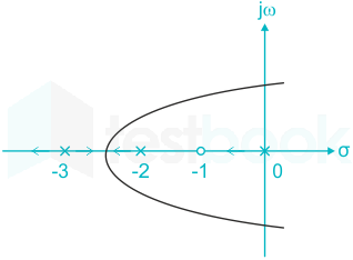
The root locus plot for a system is given below. The open loop transfer function corresponding to this plot is given by(double pole at -3)

  1. ((a))

    G(s)H(s)=ks(s+1)(s+2)(s+3)G\left( s \right)H\left( s \right) = k\frac{{s\left( {s + 1} \right)}}{{\left( {s + 2} \right)\left( {s + 3} \right)}}

  2. ((b))

    G(s)H(s)=k(s+1)s(s+2)(s+3)2G\left( s \right)H\left( s \right) = k\frac{{\left( {s + 1} \right)}}{{s\left( {s + 2} \right){{\left( {s + 3} \right)}^2}}}

  3. ((c))

    G(s)H(s)=k1s(s1)(s+2)(s+3)G\left( s \right)H\left( s \right) = k\frac{1}{{s\left( {s - 1} \right)\left( {s + 2} \right)\left( {s + 3} \right)}}

  4. ((d))

    G(s)H(s)=k(s+1)s(s+2)(s+3)G\left( s \right)H\left( s \right) = k\frac{{\left( {s + 1} \right)}}{{s\left( {s + 2} \right)\left( {s + 3} \right)}}

Show Answer
Answer: ((b))

G(s)H(s)=k(s+1)s(s+2)(s+3)2G\left( s \right)H\left( s \right) = k\frac{{\left( {s + 1} \right)}}{{s\left( {s + 2} \right){{\left( {s + 3} \right)}^2}}}

Concept:

Every branch of a root locus diagram starts at a pole (K = 0) and terminates at a zero (K = ∞) of the open-loop transfer function.

Application:

Zero = -1

Notice that there are two-locus lines going out from the pole at -3, which implies that there are two poles at s = -3,

Pole = 0, -2, -3, -3

On the real axis to the right side of any section, if the sum of total number of poles and zeros are odd, root locus diagram exists in that section.

∴ 

G(s)H(s)=k(s+1)s(s+2)(s+3)2G\left( s \right)H\left( s \right) = \frac{{k\left( {s + 1} \right)}}{{s\left( {s + 2} \right){{\left( {s + 3} \right)}^2}}}

Important Points

  1. Root locus diagram is symmetrical with respect to the real axis. 2. Number of branches of the root locus diagram are:

N = P if P ≥ Z

= Z, if P ≤ Z

3. Number of asymptotes in a root locus diagram = |P – Z| 4. Centroid: It is the intersection of the asymptotes and always lies on the real axis. It is denoted by σ.

σ=PiZiPZ\sigma = \frac{{\sum {P_i} - \sum {Z_i}}}{{\left| {P - Z} \right|}}

ΣPi is the sum of real parts of finite poles of G(s)H(s)

ΣZi is the sum of real parts of finite zeros of G(s)H(s)

5. Angle of asymptotes: θl=(2l+1)πPZ{\theta _l} = \frac{{\left( {2l + 1} \right)\pi }}{{P - Z}}

l = 0, 1, 2, … |P – Z| – 1

6. Break-in/away points: These exist when there are multiple roots on the root locus diagram.

At the breakpoints gain K is either maximum and/or minimum.

So, the roots of dKds\frac{{dK}}{{ds}} are the break points.

15

A system is defined by its impulse response h(n) = 2nu(n - 2). The system is

  1. ((a))

    stable and causal

  2. ((b))

    causal but not stable

  3. ((c))

    stable but not causal

  4. ((d))

    unstable and non-causal

Show Answer
Answer: ((b))

causal but not stable

h(n) = 2nu(n - 2)

h(n) is existing for n > 2; so that h(n) = 0; n < 0 ⇒ causal

n=h(n)=n=2n=\sum_{n = -\infty} ^{\infty} |h(n) = \sum_{n = \infty} ^{\infty}2^n = \infty \Rightarrow System is unstable

16

If the unit step response of a network is (1 – e-αt ), then its unit impulse response will be _______.

  1. ((a))

    αet/α

  2. ((b))

    1/(αe-αt)

  3. ((c))

    (1 – α)eαt

  4. ((d))

    αe-αt

Show Answer
Answer: ((d))

αe-αt

Concept:

  • The derivative of a unit-step function [u(t)] is an impulse function [δ(t)]
  • Impulse function = ddt\frac{d}{{dt}} (Unit step response)
  • Unit step function = ddt\frac{d}{{dt}} (Response of ramp function)
  • Ramp function = ddt\frac{d}{{dt}} (Response of parabolic function)


Calculation:

The unit step response of network is:

c(t) = 1 - e-αt​​​​

ddt(unit;step;response)=impulse;response\frac{d}{{dt}}\left( {unit;step;response} \right) = impulse;response

ddt(1eαt)=αeαt \frac{d}{{dt}}\left( {1 - {e^{ -α t}}} \right) = α {e^{ -α t}}

17

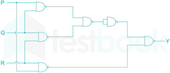
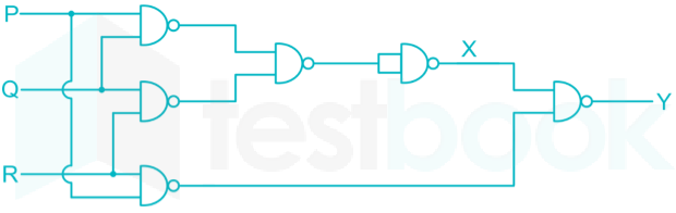
The output Y in the following circuit shown below is always 1 when

  1. ((a))

    Two or more of the inputs are zero

  2. ((b))

    Two or more of the inputs are one

  3. ((c))

    Any even number of inputs are zero

  4. ((d))

    Any even number of inputs are one

Show Answer
Answer: ((b))

Two or more of the inputs are one

From the figure,

X=PQ.QR=(PQ+QR)\rm X = \overline {PQ} .\overline {QR} = \left( {\overline {PQ + QR} } \right)

Y=(PQ+QR)PR=PQ+QR+PR\rm \therefore Y = \overline {\left( {\overline {PQ + QR} } \right)\overline {PR} } = PQ + QR + PR

if two (or) more inputs are zero,

→ Y = 0

if two (or) more inputs are one,

→ Y = 1

18

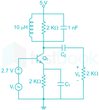
In the circuit shown below, capacitors C1C_1 and C2C_2 are very large and are shorts  at the input frequency. Vi  is a small signal input. Then the gain magnitude V0V1\left| {\frac{{{V_0}}}{{{V_1}}}} \right| at 10 M rad/s is

  1. ((a))

    maximum

  2. ((b))

    minimum

  3. ((c))

    unity

  4. ((d))

    zero

Show Answer
Answer: ((a))

maximum

For the parallel RLC circuit, the resonant frequency is

wr=1LC=110×106×1×109=10 M rad/sec{w_r} = \frac{1}{{\sqrt {LC} }} = \frac{1}{{\sqrt {10 \times {{10}^{ - 6}} \times 1 \times {{10}^{ - 9}}} }} = 10\ M\ rad/sec

∴ given circuit is in resonance

∴ impedance of parallel RLC = Zmax = R = 2KΩ

∴ gain = - gm (ZC || RL)

= - gm (2K || 2K)

∴ gain is maximum at resonance

∴ option (1) is correct

19

Drift current in semiconductors depends upon

  1. ((a))

    only the electric field

  2. ((b))

    only the carrier concentration gradient

  3. ((c))

    both the electric field and carrier concentration

  4. ((d))

    both the electric field and carrier concentration gradient

Show Answer
Answer: ((c))

both the electric field and carrier concentration

Drift currently density in a material can be given by​

J=σE\rm{J=σE}

=e(nμn+pμp)E\rm = e\left( {n{\mu _n} + p{\mu _p}} \right)E

So, Drift current in semiconductors depends upon

1) Electric charge ( 1.6 x 10⁻¹⁹  C)

  1. Mobility of charge carriers 

3) Electric Field

4) Carrier concentration

20

A zener diode, when used in voltage stabilization circuits, is biased in 

  1. ((a))

    Reverse bias region below the breakdown voltage

  2. ((b))

    Reverse breakdown region

  3. ((c))

    Forward bias region

  4. ((d))

    Forward bias constant current mode

Show Answer
Answer: ((b))

Reverse breakdown region

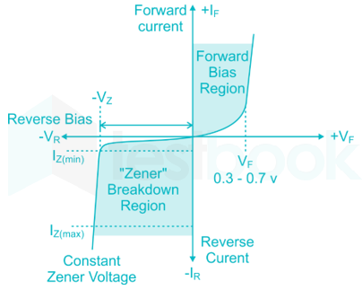
  • The forward voltage rating of Zener diode is the same as a normal diode
  • A zener diode is used as a voltage regulator in reversed biased where voltage across it remains constant as shown in the figure
  • The slope (V/I) is positive
  • At reverse breakdown voltage (typically around 5V), there is a sharp breakdown at a reverse voltage as shown in the figure

21

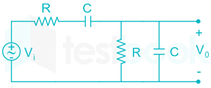
The circuit shown below is driven by a sinusoidal input, Vi=Vpcos(tRC).{V_i} = {V_p}\cos \left( {\frac{t}{{RC}}} \right). The steady state output V0{V_0} is,

  1. ((a))

    VP3cos(tRC)\frac{{{V_P}}}{3}{\rm{cos}}\left( {\frac{t}{{RC}}} \right)

  2. ((b))

    VP3sin(tRC)\frac{{{V_P}}}{3}{\rm{sin}}\left( {\frac{t}{{RC}}} \right)

  3. ((c))

    VP2cos(tRC)\frac{{{V_P}}}{2}{\rm{cos}}\left( {\frac{t}{{RC}}} \right)

  4. ((d))

    VP2sin(tRC)\frac{{{V_P}}}{2}{\rm{sin}}\left( {\frac{t}{{RC}}} \right)

Show Answer
Answer: ((a))

VP3cos(tRC)\frac{{{V_P}}}{3}{\rm{cos}}\left( {\frac{t}{{RC}}} \right)

We can see from the circuit,

VoutVin=(RXc)(RXc)+R+Xc\begin{array}{l} \frac{{{V_{out}}}}{{{V_{in}}}} = \frac{{(R||{X_c})}}{{(R||{X_c}) + R + {X_c}}} \end{array}

Solving the above by putting Xc=1jωCX_c=\frac{1}{j\omega C} we get,

VoutVin=jωRCjωRC+(1+jωRC)2\frac{{{V_{out}}}}{{{V_{in}}}} = \frac{{jω RC}}{{jω RC + {{\left( {1 + jω RC} \right)}^2}}}

Given:

Vin=cos(tRC)V_{in}=\cos \left( {\frac{t}{{RC}}} \right)    ---(1)

By comparing (1) with cos(ωt), we get

  ω=1RCω = \frac{1}{{RC}} 

∴ VoutVin=jj+(1+j)2=13\frac{{{V_{out}}}}{{{V_{in}}}} = \frac{j}{{j + {{\left( {1 + j} \right)}^2}}} = \frac{1}{3}

Vout=13Vi∴ {V_{out}} = \frac{1}{3}{V_i}

=Vp3 cos(tRC)= \frac{{{V_p}}}{3}~{\rm{cos}}( {\frac{t}{{RC}}})

22

Consider a closed surface S surrounding volume V. If r{\rm{\vec r}} is the position vector of a point inside S, with the unit normal n{\rm{\vec n}} on S, the value of the integral \(\smallint \mathop \smallint \limits_{\rm{s}}^{\rm{;}} 5{\rm{\vec r}} \cdot {\rm{\vec nds;}}\)is

  1. ((a))

    3V

  2. ((b))

    5V

  3. ((c))

    10V

  4. ((d))

    15V

Show Answer
Answer: ((d))

15V

From Divergence theorem, we have Adv=s;An^;ds\int \int \int \vec \nabla \cdot {\rm{\vec Adv}} = \mathop \oint \limits_{\rm{s}}^{\rm{;}} {\rm{\vec A}} \cdot {\rm{\hat n;ds}}

The position vector  \({\rm{\vec r}} = \left( {{{{\rm{\hat u}}}{\rm{x}}}{\rm{x}} + {{{\rm{\hat u}}}{\rm{y}}}{\rm{y}} + {{{\rm{\hat u}}}_{\rm{z}}}{\rm{z}}} \right)\)

Here,;A=;5r,;thus{\rm{Here}},{\rm{;\vec A}} = {\rm{;}}5{\rm{\vec r}},{\rm{;thus}}

\(\nabla \cdot {\rm{\vec A}} = \left( {{{{\rm{\hat u}}}{\rm{x}}}\frac{\partial }{{\partial {\rm{;x}}}} + {{{\rm{\hat u}}}{\rm{y}}}\frac{\partial }{{\partial {\rm{;y}}}} + {{{\rm{\hat u}}}{\rm{z}}}\frac{\partial }{{\partial {\rm{;z}}}}} \right) \cdot 5\left( {{{{\rm{\hat u}}}{\rm{x}}}{\rm{x}} + {{{\rm{\hat u}}}{\rm{y}}}{\rm{y}} + {{{\rm{\hat u}}}{\rm{z}}}{\rm{z}}} \right)\)

=(xx+yy+zz)5=3×5=15 = \left( {\frac{{{\rm{\partial x}}}}{{{\rm{\partial x}}}} + \frac{{{\rm{\partial y}}}}{{{\rm{\partial y}}}} + \frac{{{\rm{\partial z}}}}{{{\rm{\partial z}}}}} \right)5 = 3 \times 5 = 15

So, !!!s;5;rn^;ds=;15;dv=15;V\mathop \int!!!\int \limits_{\rm{s}}^{\rm{;}} 5{\rm{;\vec r}} \cdot {\rm{\hat n;ds}} = \int \int \int {\rm{;}}15{\rm{;dv}} = 15{\rm{;V}}

23

The modes in a rectangular waveguide are denoted by TEmn/TMmn where m and n are the eigen numbers along the larger and smaller dimensions of the waveguide respectively. Which one of the following statements is TRUE?

  1. ((a))

    The TM10 mode of the waveguide does not exist

  2. ((b))

    The TE10 mode of the waveguide does not exist

  3. ((c))

    The TM10 and the TE10 modes both exist and have the same cut-off frequencies

  4. ((d))

    The TM10 and the TM01 modes both exist and have the same cut-off frequencies

Show Answer
Answer: ((a))

The TM10 mode of the waveguide does not exist

For a TEmn mode to exist, We need to have  m,n = 0,1,2,......

but does not exist for m = n = 0. For all other combinations TEmn exists.

For a TMmn mode to exist, We need to have m,n = 1,2,3, ....... i.e m & n both must be non-zero

⇒ TM01, TM10 modes do not exist

Important Points Waveguides only allow frequencies above the cut-off frequency to pass through. It blocks or attenuates the frequencies below the cut-off frequencies.

The cut off frequency is mathematically calculated as:

fc(min)=c2(ma)2+(nb)2{{f}_{c\left( min \right)}}=\frac{c}{2}\sqrt{{{\left( \frac{m}{a} \right)}^{2}}+{{\left( \frac{n}{b} \right)}^{2}}}

Where a and b are the dimensions of the waveguide

m and n are mode numbers TEmn.

24

The solution of the differential equation (dy/dx) = ky, y(0) = c is

  1. ((a))

    x = ce-ky

  2. ((b))

    x = kecy

  3. ((c))

    y = cekx

  4. ((d))

    y = ce-kx

Show Answer
Answer: ((c))

y = cekx

The given differential equation is, (dy/dx) = ky

dyy=kdx\frac{{dy}}{y} = kdx

On integrating both the sides, we get

ln y = kx + ln c

y = cekx

25

The list 1 lists the attribution and List II lists the modulation system. Match the attribute to the modulation system that best matches it

List IList II
P.         Power efficient transmission of signal.1.Conventional AM
Q.        Most bandwidth efficient transmission of voice signals.2. FM
R.        Simplest receiver structure.3. VSB
S.         B.W efficient transmission of signals with significant DC component.4. SSB
  1. ((a))

    P – 4, Q – 2, R - 1, S – 3

  2. ((b))

    P – 2, Q – 4, R – 1, S– 3

  3. ((c))

    P – 3, Q – 2, R – 1, S– 4

  4. ((d))

    P – 2, Q – 4, R – 3, S– 1

Show Answer
Answer: ((b))

P – 2, Q – 4, R – 1, S– 3

Advantages of FM over AM are:

  • Improved signal to noise ratio.
  • Smaller geographical interference between neighbouring stations.
  • Less radiated power.
  • Well defined service areas for given transmitter power.
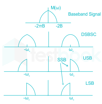
  • In SSB (Single Side-band), only one side-band is necessary for the transmission of information.
  • This reduces the Bandwidth requirement to half.
  • A typical SSB transmission spectrum is as shown:


  • For SSB transmission, it does not matter whether the upper or lower sideband is used, since the information is contained in both.

Vestigial Side Band (VSB):

VSB (vestigial sideband) transmission transmits one sideband fully and the other sideband partially thus, reducing the bandwidth requirement.

26

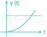
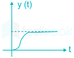
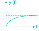
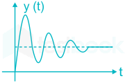
The differential equation 100dydt220dydt+y=x(t)100\frac{d^y}{dt^2}- 20\frac{dy}{dt}+ y = x(t) describes a system with an input x(t) and an output y(t). The system, which is initially relaxed, is excited by a unit step input. The output y(t) can be represented by the waveform

  1. ((a))

  2. ((b))

  3. ((c))

  4. ((d))

Show Answer
Answer: ((a))

100d2ydt220dydt+y=x(t)\frac{100d^2y}{dt^2}-\frac{20dy}{dt}+ y = x(t)

Apply L.T. both sides

(100s2 - 20s + 1) Y(s) = 1s\frac{1}{s}  [x(t)×(s)=13][\because x(t) \times (s) = \frac{1}{3}]

Y(s)=1s(100s220s+1)Y(s) = \frac{1}{s(100s^2 - 20s + 1)}

So we have poles with positive real part ⇒ system is unstable.

27

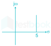
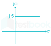
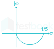
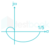
For the transfer function G (jω) = 5 + jω, the corresponding Nyquist plot for positive frequency has the form

  1. ((a))

  2. ((b))

  3. ((c))

  4. ((d))

Show Answer
Answer: ((a))

G (jω) = 5 + jω

 ω = 0  

 G (jω) = 5 + j 0 

 ω = 10  

 G (jω) = 5 + j 10 

 ω = ∞ 

 G (jω) = 5 + j ∞ 

 ∴ G (jω) is a straight line parallel to jω axis

28

The trigonometric Fourier series of an even function does not have the

  1. ((a))

    DC terms

  2. ((b))

    Sine terms

  3. ((c))

    Cosine terms

  4. ((d))

    Odd harmonic terms

Show Answer
Answer: ((b))

Sine terms

The Fourier series for the function f(x) in the interval α < x < α + 2π is given by

\(f\left( x \right) = \frac{{{a_o}}}{2} + \mathop \sum \limits_{n = 1}^\infty {a_n}\cos nx + \mathop \sum \limits_{n = 1}^\infty {b_n}\sin nx\)

where

\({a_o} = \frac{1}{\pi }\mathop \smallint \limits_\alpha ^{\alpha + 2\pi } f\left( x \right)dx;;{a_n} = \frac{1}{\pi }\mathop \smallint \limits_\alpha ^{\alpha + 2\pi } f\left( x \right)\cos nxdx;;{b_n} = \frac{1}{\pi }\mathop \smallint \limits_\alpha ^{\alpha + 2\pi } f\left( x \right)\sin nxdx\)

An even function is any function f such that f(-x) = f(x)

Example: cos x, sec x, x2, x4, x6 …….., x-2, x-4 ……..

An odd function is any function f such that f(-x) = -f(x)

Example: sin x, tan x, cosec x, cot x, n, x3 ……., x-1, x-3 ……..

\(\mathop \smallint \limits_{ - L}^L f\left( x \right)dx = \left{ {\begin{array}{*{20}{c}} {2\mathop \smallint \limits_0^L f\left( x \right)dx,;;when;f\left( x \right);is;an;even;function}\ {0,;;when;f\left( x \right);is;an;odd;function} \end{array}} \right.\)

When f is an even periodic function of period 2L, then its Fourier series contains only cosine (include possibly, the constant term) terms.

\(f\left( x \right) = \frac{{{a_o}}}{2} + \mathop \sum \limits_{n = 1}^\infty {a_n}\frac{{\cos n\pi x}}{L}\)

\({a_o} = \frac{1}{L}\mathop \smallint \limits_{ - L}^L f\left( x \right)dx = \frac{2}{L}\mathop \smallint \limits_0^L f\left( x \right)dx\)

\({a_n} = \frac{1}{L}\mathop \smallint \limits_{ - L}^L f\left( x \right)\cos \frac{{n\pi x}}{L}dx = \frac{2}{L}\mathop \smallint \limits_0^L f\left( x \right)\cos \frac{{n\pi x}}{L}dx\)

When f is an odd periodic function of period 2L, then its Fourier series contains only sine terms.

\(f\left( x \right) = \mathop \sum \limits_{n = 1}^\infty {b_n}\sin \frac{{n\pi x}}{L}\)

\({b_n} = \frac{1}{L}\mathop \smallint \limits_{ - L}^L f\left( x \right)\sin \frac{{n\pi x}}{L}dx = \frac{2}{L}\mathop \smallint \limits_0^L f\left( x \right)\sin \frac{{n\pi x}}{L}dx\)


SymmetryConditionFourier series
Evenf(t) = f(-t)The DC and cosine terms can exist
Oddf(t) = -f(-t)Sine terms can exist
Half wavef(t ± T/2) = -f(t)Odd harmonics
f(t ± T/2) = f(t)Even harmonics
29

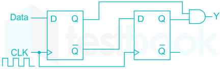
When the output Y in the circuit below is ‘’1’’, it implies that data has

  1. ((a))

    Changed from “0” to “1”

  2. ((b))

    Changed from “1” to “0”

  3. ((c))

    Changed in either direction

  4. ((d))

    Not changed

Show Answer
Answer: ((a))

Changed from “0” to “1”

Concept:

D flip-flop can be built using NAND gate or with NOR gate. Whenever the clock signal is LOW, the input is never going to affect the output state. The clock has to be high for the inputs to get active. Thus, D flip-flop is a controlled Bi-stable latch where the clock signal is the control signal. Again, this gets divided into positive edge triggered D flip flop and negative edge triggered D flip-flop

Truth table of D Flip-Flop:

ClockINPUTOUTPUT
DQQ’
LOWx01
HIGH001
HIGH110


New,

 yn=Q1nQ2n{y_n} = {Q_{{1_n}}}{Q_{{2_n}}}

=Q1nD2n= {Q_{{1_n}}}{D_{{2_n}}}

=Q1nQ1(n1)= {Q_{{1_n}}}\overline {{Q_{{1_{\left( {n - 1} \right)}}}}}

=D1nD1(n1) = {D_{{1_n}}}\overline {{D_{{1_{\left( {n - 1} \right)}}}}}

The output will be high when,

 D1(n1)=0 and D1n=1{D_{{1_{\left( {n - 1} \right)}}}} = 0\ and\ {D_{{1_n}}} = 1

i.e when the data changes from ‘0’ to ‘1’

30

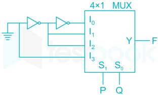
The logic function implemented by the multiplexer circuit is (ground implies a logic “0”)

  1. ((a))

    F = AND (P, Q)

  2. ((b))

    F = OR (P, Q)

  3. ((c))

    F = XNOR (P, Q)

  4. ((d))

    F = XOR (P, Q)

Show Answer
Answer: ((d))

F = XOR (P, Q)

Concept:

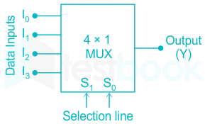
In a 4 × 1 MUX

Truth-Table

S1S0V
00I0
01I1
10I2
11I3


Y = Output = S̅1 0 I0 + S̅1 S0 I1 + S10 I2 + S1 S0 I3

MUX contains AND gate followed by OR gate

Calculation:

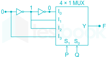
By re-drawing circuit diagram

∴ I0 = 0, I1 = 1, I2 = 1, I3 = 0 & (P = S1, Q = S0)

Now output of 4 × 1 MUX is

Y = F = (P̅ Q̅) 0 + (P̅ Q)1 + (P Q̅) 1 + (P Q)0

∴ F = P Q̅ + P̅ Q = P ⊕ Q

∴ F = XOR (P, Q)

31

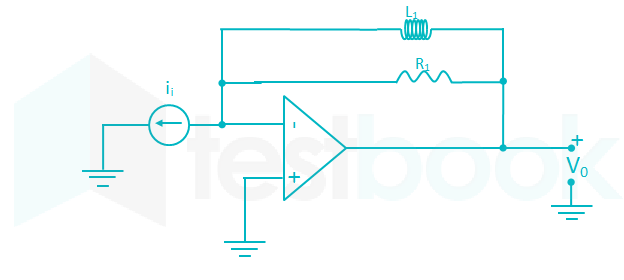
The circuit below implements a filter between input current i1 and output voltage v0. Assume that the opamp is ideal. The filter implemented is a

  1. ((a))

     Low pass filter

  2. ((b))

    Band pass filter                                                           

  3. ((c))

    Band stop filter

  4. ((d))

    High pass filter

Show Answer
Answer: ((d))

High pass filter

At low frequencies,

 i.e. w=0: L S.Ci.e. \ w=0 : \ L\rightarrow\ S.C

 V0 =0V\therefore\ V_0\ =0V

similarly at higher frequencies,

 i.e.w=:L O.Ci.e. w=\infty:L\rightarrow\ O.C

 V0=iiR1\therefore\ V_0=i_iR_1  

So, the given circuit passes only high frequencies so it acts like a high pass filter.

32

A silicon PN junction is forward biased with a constant current at room temperature. When the temperature is increased by 10°C, the forward bias voltage across the PN junction  

  1. ((a))

    Increases by 60 mV

  2. ((b))

    Decreases by 60 mV

  3. ((c))

    Increase by 25 mV

  4. ((d))

    Decreases by 25 mV

Show Answer
Answer: ((d))

Decreases by 25 mV

For Si diode:

The forward bias voltage change by – 2.5mV/°C.

Thus, for 10°C change in temperature change in forward bias.

ΔV=2.5mVC×10C;{\rm{\Delta }}V = - 2.5\frac{{mV}}{{^\circ C}} \times 10^\circ C;

=25mV=-25 mV

Note : It may be noted here that reverse saturation current doubles for every 10 °C rise in temperature

33

In the circuit shown below, Norton equivalent current in Ampere with respect to terminal P & Q is

  1. ((a))

    6.4j 4.86.4 - j\ 4.8

  2. ((b))

    6.56j 7.876.56 - j\ 7.87

  3. ((c))

    10j 5010 - j\ 50

  4. ((d))

    16j 016 - j\ 0

Show Answer
Answer: ((a))

6.4j 4.86.4 - j\ 4.8

Converting current source into voltage source form, we get

The capacitor is connected across the short circuited branch hence it can be removed.

ISC=400040+j30 =6.4j4.8 A\begin{array}{l} \therefore {I_{SC}} = \frac{{400\angle {0^\circ }}}{{40 + j30}}\ = 6.4 - j4.8\ A \end{array}

(1) is correct.

34

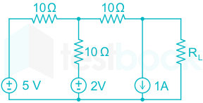
In the circuit shown below, the value of RL such that the power transferred to RL is maximum is

  1. ((a))

    5 Ω

  2. ((b))

    10 Ω

  3. ((c))

    15 Ω

  4. ((d))

    20 Ω

Show Answer
Answer: ((c))

15 Ω

Concept:

From LMS

Calculation:

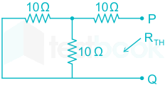
RTH = (10 || 10) + 10 = 15 Ω

35

The value of the integral c;3z+5z2+4z+5dz\mathop \oint \limits_c^; \frac{{ - 3z + 5}}{{{z^2} + 4z + 5}}dz where C is the circle |z| = 1 is given by,

  1. ((a))

    0

  2. ((b))

    110\frac{1}{{10}}

  3. ((c))

    45\frac{4}{5}

  4. ((d))

    1

Show Answer
Answer: ((a))

0

Concept:

Cauchy’s Theorem:

If f(z) is an analytic function and f’(z) is continuous at each point within and on a closed curve C, then

Cf(z)dz=0\mathop \oint \limits_C f\left( z \right)dz = 0

Calculation:

c;3z+5z2+4z+5dz\mathop \oint \limits_c^; \frac{{ - 3z + 5}}{{{z^2} + 4z + 5}}dz

Where c is circle |z| = 1

Here poles are at,

z = -2 ± j which are outside the unit circle

Hence,

 c;3z+5z2+4z+5dz=0\mathop \oint \limits_c^; \frac{{ - 3z + 5}}{{{z^2} + 4z + 5}}dz = 0

36

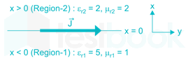
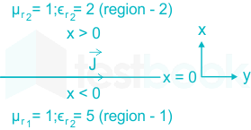
A current sheet J=10u^y;A/m\vec J = 10{\hat u_y};A/m lies on the dielectric interface x = 0 between two dielectric media with εr1;=;5,;μr1;=;1{\varepsilon _{r1}}; = ;5,;{\mu _{r1}}; = ;1 in Region–1 (x < 0) and εr2;=;2,;μr2;=;2{\varepsilon _{r2}}; = ;2,;{\mu _{r2}}; = ;2 Region–2 (x > 0). If the magnetic field in Region-1 at x = 0 is H1=3u^x+30u^y;A/m{\vec H_1} = 3{\hat u_x} + 30{\hat u_y};A/m the magnetic field in Region-2 at x = 0+ is 

  1. ((a))

    H2=1.5u^x+30u^y10u^zAm{\vec H_2} = 1.5{\hat u_x} + 30{\hat u_y} - 10{\hat u_z}\frac{A}{m}

  2. ((b))

    H2=3u^x+30u^y10u^zAm{\vec H_2} = 3{\hat u_x} + 30{\hat u_y} - 10{\hat u_z}\frac{A}{m}

  3. ((c))

    H2=1.5u^x+40u^yAm{\vec H_2} = 1.5{\hat u_x} + 40{\hat u_y}\frac{A}{m}

  4. ((d))

    H2=3u^x+30u^y+10u^zAm{\vec H_2} = 3{\hat u_x} + 30{\hat u_y} + 10{\hat u_z}\frac{A}{m}

Show Answer
Answer: ((a))

H2=1.5u^x+30u^y10u^zAm{\vec H_2} = 1.5{\hat u_x} + 30{\hat u_y} - 10{\hat u_z}\frac{A}{m}

Boundary conditions for magnetic field are

Bn1=Bn2{B_{{n_1}}} = {B_{{n_2}}} and Ht1Ht2=Js×a^n{H_{{t_1}}} - {H_{{t_2}}} = - {\vec J_s} \times {\hat a_n}

Bx1=Bx2 \Rightarrow {B_{{x_1}}} = {B_{{x_2}}} .......(x is normal direction) 

Hx2=1×3u^x2\Rightarrow {H_x}_2 = \frac{{1 \times 3{{\hat u}_x}}}{2}

Hx2=1.5u^x{H_x}_2 = 1.5{\hat u_x}

Now, 

(Ht1Ht2)=;(10u^y)×(u^x)\left( {{H_t}_1 - {H_t}_2} \right) = ; - \left( {10{{\hat u}_y}} \right) \times \left( {{{\hat u}_x}} \right)

 =;10;u^z\ = {\rm{;}}10{\rm{;}}{\hat u_z}

Ht2=Ht110u^z=30u^y10u^z{H_{{t_2}}} = {H_{{t_1}}} - 10{\hat u_z} = 30{\hat u_y} - 10{\hat u_z}

Ht2=30u^y10u^z\Rightarrow {H_t}_2 = 30{\hat u_y} - 10{\hat u_z}

\(\Rightarrow {\vec H_2} = {\vec H_x}2 + {\vec H{{t_2}}} = 1.5{\hat u_x} + 30{\hat u_y} - 10{\hat u_z}\)

37

A transmission line of characteristic impedance 50 Ω is terminated in a load impedance ZL. The VSWR of the line is measured as 5 and first of the voltage maxima in the line is observed at a distance of λ/4 from the load. The value of ZL is

  1. ((a))

    10 Ω

  2. ((b))

    250 Ω

  3. ((c))

    (19.23 + j46.15) Ω

  4. ((d))

    (19.23 – j46.15) Ω

Show Answer
Answer: ((a))

10 Ω

VSWR =;5;=;1+Γ1ΓΓ=23Γ=±23= ;5; = ;\frac{{1 + \left| \Gamma \right|}}{{1 - \left| \Gamma \right|}} \Rightarrow \left| \Gamma \right| = \frac{2}{3} \Rightarrow \Gamma = \pm \frac{2}{3}

Maxima at distance  λ4\frac{\lambda }{4} from load

⇒ minima at load itself

ZL<ZΓ=23\Rightarrow {Z_L} < Z \Rightarrow \Gamma = - \frac{2}{3}


Γ=ZLZoZL+Zo=23ZL50ZL+50=23ZL=10;Ω \Rightarrow \Gamma = \frac{{{Z_L} - {Z_o}}}{{{Z_L} + {Z_o}}} = - \frac{2}{3} \Rightarrow \frac{{{Z_L} - 50}}{{{Z_L} + 50}} = - \frac{2}{3} \Rightarrow {Z_L} = 10;\Omega

38

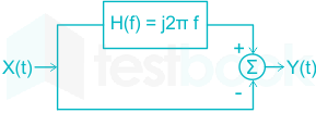
X(t) is a stationary random process with autocorrelation function Rx(τ) = exp(-πτ2). This process is passed through the system shown below. The power spectral density of the output process Y(t) is

  1. ((a))

    (4π2f2 + 1) exp(-πf2)

  2. ((b))

    (4π2f2 - 1) exp(-πf2)

  3. ((c))

    (4π2f2 + 1) exp(-πf)

  4. ((d))

    (4π2f2 - 1) exp(-πf)

Show Answer
Answer: ((a))

(4π2f2 + 1) exp(-πf2)

The total transfer function H(f) = (j2πf - 1)

Sx(f) = |H(f)|2 Sx(f) Rx(τ) F\overset{F}{\large\leftrightarrow} Sx(f)

= (4π2f2 + 1)e-πt2 (∵ e-πt2 F\overset{F}{\large\leftrightarrow} e-πt2)

39

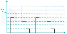
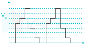
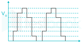
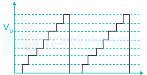
The output of a 3-stage Johnson (twisted-ring) counter is fed to a digital-to-analog (D/A) converter as shown in the figure below. Assume all states of the counter to be unset initially. The waveform which represents the D/A converter output Vo is

  1. ((a))

  2. ((b))

  3. ((c))

  4. ((d))

Show Answer
Answer: ((a))

The initial state of the Johnson counter is as follows –

                                    D2        D1        D0

            State -1            0          0          0

            State-2             1          0          0

            State-3             1          1          0

            State-4             1          1          1

            State-5             0          1          1

            State-6             0          0          1

            State-7             0          0          0                      (it is equivalent to state 1)

            So the corresponding digital output assuming LSB bit contribute unit Analog output is –

State 10
State 24
State 36
State 47
State 53
State 61
<br>

So, option (1) is correct.

40

Two D flip-flops are connected as a synchronous counter that goes through the following QBQA sequence 00 “ 11 “ 01 “ 10 “ 00 “ … The combination of the inputs DA and DB are

  1. ((a))

    DA = QB ; DB = QA

  2. ((b))

    DA = QA ; DB = QB

  3. ((c))

    DA = (Q̅AQ̅B + QAQB ; DB = QA

  4. ((d))

    DA = (Q̅AB + QAQB) ; DB = Q̅B

Show Answer
Answer: ((d))

DA = (Q̅AB + QAQB) ; DB = Q̅B

Concept:

Synchronous Counters are so-called because the clock input of all the individual flip-flops within the counter are all clocked together at the same time by the same clock signal.

With the Synchronous Counter, the external clock signal is connected to the clock input of EVERY individual flip-flop within the counter so that all of the flip-flops are clocked together simultaneously (in parallel) at the same time giving a fixed time relationship.

Example of the Synchronous up counter with the waveforms is shown below:


Calculation:

Given counting sequence is 

The construction of the truth table is explained below:

Excitation table of D flip flop

Output equations for the flip flops are

For DB

<sub>

</sub>

\({{\bf{D}}{\bf{B}}} = \overline {{{\bf{Q}}{\bf{B}}}} \)

For DA

<sub>

</sub>

DA=QB;QA+QBQA{D_A} = \overline {{Q_B}} ;\overline {{Q_A}} + {Q_B}{Q_A}

\({{\bf{D}}{\bf{A}}} = {{\bf{Q}}{\bf{B}}} \odot {{\bf{Q}}_{\bf{A}}}\)

41

In the circuit shown below, for the MOS transistors μnCOX = 100 μA/V2 and the threshold voltage VT = 1V. The voltage Vx at the source of the upper transistor is 

  1. ((a))

    1 V

  2. ((b))

    2 V

  3. ((c))

    3 V

  4. ((d))

    3.67 V

Show Answer
Answer: ((c))

3 V

Since the Gate and Drain of pull-down transistor is shorted. So it has operated in the saturation region, let pull up transistor operated in the saturation region.

Then ID1 = ID2

\(\frac{1}{2}{\mu n}{C{ox}}{\left( {\frac{\omega }{L}} \right)1}{\left( {{V{GS1}} - V_{T1}} \right)^2}\)

\( = \frac{1}{2}{\mu n}{C{ox}}{\left( {\frac{\omega }{L}} \right)2}{\left( {{V{Gs2}} - V_{T2}} \right)^2}\)

4 [5 – Vx - 1]2 = 1[Vx - 1]2

2(4 - Vx) = Vx – 1

9 = 3 Vx → Vx = 3V

VGS1 = 5 – 3 = 2, VDS1 = 6 – 3 = 3V

∴ VDS1 > (VGS1 – VT1)

So our assumption is correct

∴ Vx = 3 V

So option (3) is correct.

42

An input x(t) = exp(-2t) u(t) + δ(t - 6) is applied to an LTI system with impulse response h(t) = u(t). The output is

  1. ((a))

    [1 - exp(-2t) u(t)] + u(t + 6)

  2. ((b))

    [1 - exp(-2t)] u(t) + u(t + 6)

  3. ((c))

    0.5[1 - exp(-2t)] u(t) + u(t + 6)

  4. ((d))

    0.5[1 - exp(-2t)] u(t) + u(t - 6)

Show Answer
Answer: ((d))

0.5[1 - exp(-2t)] u(t) + u(t - 6)

X(s)=1s+2+e6sand H(s)=1sX(s) = \frac{1}{s + 2} + e^{-6s} \text {and H}(s) = \frac{1}{s}

Y(s)=H(s)×(s)=1s(s+2)+e6ss=121s12(s+2)+e6ssY(s) = H(s) \times (s) = \frac{1}{s(s+2)}+\frac{e^{-6s}}{s}=\frac{1}{2}\frac{1}{s}-\frac{1}{2(s+2)}+\frac{e^{-6s}}{s}

⇒ y(t) = 0.5(1 - e-2t) u(t) + u(t - 6)

43

For a BJT, the common-base current gain α;=;0.98\alpha ; = ;0.98 and the collector base junction reverse bias saturation current ICO = 0 .6 μA. This BJT is connected in the common emitter mode and operated in the active region with a base drive current IB = 20 μA  . The collector current IC for this mode of operation is:

  1. ((a))

    0.98mA

  2. ((b))

    0.99mA

  3. ((c))

    1.0mA

  4. ((d))

    1.01mA

Show Answer
Answer: ((d))

1.01mA

Concept:

Current gain β is given as:

β=α1α\beta = \frac{\alpha }{{1 - \alpha }}

Collector current in terms of reverse bias saturation current is given as:

Ic=βIB+(1+β)Is{I_c}={β{I_B}}+{\left(1+β\right)}I_s

Calculation:

Given:

Is = 0.6μA

α=0.98

IB= 20µA

β=0.9810.98=49\beta = \frac{0.98}{{1 - 0.98}}=49

putting values,

Ic=49×20μA+(50)×0.6μA{I_c}={49\times{20μ{A}}}+{\left(50\right)}\times0.6μ{A}

Ic=0.98mA+0.03mA=1.01mA{I_c}=0.98{m}A+0.03{m}A=1.01mA

44

If F(s)=L[f(t)]=(2s+1)s2+4s+7F(s) = L[f(t)] = \frac{(2s+1)}{s^2 + 4s + 7} then the initial and final values of f(t) are respectively.

  1. ((a))

    0, 2

  2. ((b))

    2, 0

  3. ((c))

    0, 2/7

  4. ((d))

    2/7, 0

Show Answer
Answer: ((b))

2, 0

Concept:

By initial value theorem,

Initial value of f(t) is given by,

limt0f(t)=limssF(s)\mathop {\lim }\limits_{t \to 0} f\left( t \right) = \mathop {\lim }\limits_{s \to \infty } sF\left( s \right)      ---(1)

Final value of f(t) is given by,

limtf(t)=lims0;sF(s)\mathop {\lim }\limits_{t \to \infty } f\left( t \right) = \mathop {\lim }\limits_{s \to 0} ;sF\left( s \right)      ---(2)

Calculation:

limtof(t)=lim(s)s(2s+1)s2+4s+7=2\displaystyle\lim_{t \rightarrow o}f(t) = \displaystyle\lim_{(s \rightarrow \infty)} \frac{s(2s + 1)}{s^2 + 4s + 7}=2

limtf(t)=lim(s0)s(2s+1)s2+4s+7=0\displaystyle\lim_{t \rightarrow \infty}f(t) = \displaystyle\lim_{(s \rightarrow 0)} \frac{s(2s + 1)}{s^2 + 4s + 7}=0

45

In the circuit shown below, current I is equal to

  1. ((a))

    1.4 0 A1.4\ \angle {0^\circ }\ A

  2. ((b))

    2.0 0 A2.0\ \angle {0^\circ }\ A

  3. ((c))

    2.8 0 A2.8\ \angle {0^\circ }\ A

  4. ((d))

    3.2 0 A3.2\ \angle {0^\circ }\ A

Show Answer
Answer: ((b))

2.0 0 A2.0\ \angle {0^\circ }\ A

From star to delta conversion

R1=RaRbRa+Rb+Rc=2 Ω{R_1} = \frac{{{R_a}{R_b}}}{{{R_a} + {R_b} + {R_c}}} = 2\ \Omega

Similarly,   R2=R3=R1=2 Ω{R_2} = {R_3} = {R_1} = 2\ \Omega

∴The circuit will be like

Z=((2+j4))(2j4))+2 Z=204+2=7;Ω I=VZ=1407=20A\begin{array}{l} \therefore Z = \left( {\left( {2 + j4} \right)} \right)||\left( {2 - j4} \right)) + 2\ Z=\frac{20}{4}+2 = 7; \Omega \ \therefore I =\frac{V}{Z}= \frac{{14\angle {0^\circ }}}{7} = 2\angle {0^\circ }A \end{array}

46

A numerical solution of the equation f(x)=x+x3=0f(x) = x + \sqrt x - 3 = 0can be obtained using Newton-Raphson method. If the starting value is x = 2 for the iteration, the value of x that is to be used for the next step is

  1. ((a))

    1.693

  2. ((b))

    1.683

  3. ((c))

    1.720

  4. ((d))

    1.673

Show Answer
Answer: ((a))

1.693

Concept:

Using Newton-Raphson method

x1=x0f(x0)ddxf(x0)\mathop x\nolimits_1 = \mathop x\nolimits_0 - \frac{{f(\mathop x\nolimits_0 )}}{{\frac{d}{{dx}}f(\mathop x\nolimits_0 )}}

Calculation:

xo=2\mathop x\nolimits_o = 2

ddxf(x)=1+12x\frac{d}{{dx}}f(x) = 1 + \frac{1}{{2\sqrt x }}

at x0 = 2

ddxf(2)=1+122\frac{d}{{dx}}f(2) = 1 + \frac{1}{{2\sqrt 2 }}

x1=2f(2)ddxf(2)=2[2+23][1+122]=1.693 \begin{array}{l} \mathop x\nolimits_1 = 2 - \frac{{f(2)}}{{\frac{d}{{dx}}f(2)}} = 2 - \frac{{\left[ {2 + \sqrt 2 - 3} \right]}}{{\left[ {1 + \frac{1}{{2\sqrt 2 }}} \right]}} = 1.693\ \end{array}

47

The electric and magnetic fields for a TEM wave of frequency 14 GHz in a homogenous medium of relative permittivity εr and relative permeability μr = 1 are given by

\(\vec E = {E_P}{e^{j\left( {\omega t - 280\pi y} \right)}}{\hat u_z}\frac{V}{m}\) and H=3 ej(ωt280πy) u^xAmH = 3~{e^{j\left( {\omega t - 280\pi y} \right)}}~{\hat u_x}\frac{A}{m}

Assuming the speed of light in free space to be 3 × 10⁸ m/s, the intrinsic impedance of free space to be 120π, the relative permittivity εr of the medium and the electric field amplitude EpE_p are

  1. ((a))

    εr = 3, Ep = 120π

  2. ((b))

    εr = 3, Ep = 360π

  3. ((c))

    εr = 9, Ep = 360π

  4. ((d))

    εr = 9, Ep = 120π

Show Answer
Answer: ((d))

εr = 9, Ep = 120π

E=Ep.ej(ωt280πy);;u^z vm\vec E = {E_p}.{e^{j\left( {\omega t - 280\pi y} \right)}};;{\hat u_z}~\frac{v}{m}

\(H = 3~{e^{j\left( {\omega t - 280\pi y} \right)}}{\hat u_x}\frac{A}{m}\)

c=3×10⁸ m/sc = 3 \times {10^8}~m/s  (speed of light)

β=280;π=2πλ\beta = 280;\pi = \frac{{2\pi }}{\lambda }

 λ=1140m \lambda = \frac{1}{{140}}m

v=fλ v = f\lambda

v=14×109×1140v= 14 \times {10^9} \times \frac{1}{{140}}

v=1×10⁸v = 1 \times {10^8}

v=cϵr\Rightarrow v = \frac{c}{{\sqrt {{\epsilon_r}} }}

ϵr=(cv)2 {\epsilon_r} = {\left( {\frac{c}{v}} \right)^2}

ϵ=(3×1081×108)2=9\epsilon= {\left( {\frac{{3 \times {{10}^8}}}{{1 \times {{10}^8}}}} \right)^2} =9

Ep=Hη=H.ηoϵr{E_p} = \left| {\vec H} \right|\eta = \frac{{\left| {\vec H} \right|.{\eta _o}}}{{\sqrt {{\epsilon_r}} }}

=3×120π9=120;π= \frac{{3 \times 120\pi }}{{\sqrt 9 }} = \textbf{120};\pi

48

A message signal m(t);=;cos2000πt+4cos;4000πtm\left( t \right); = ;cos2000\pi t + 4cos;4000\pi t modulates the carrier c(t)=cos2πfctc\left( t \right) = cos2\pi {f_c}t where fc = 1 MHz to produce AM. For demodulating the generated AM signal using an envelope defector, the time constant RC of the defector should satisfy

  1. ((a))

    0.5 < RC < 1 ms

  2. ((b))

    1μs ≪ RC < 0.5 ms

  3. ((c))

    RC ≪ 1μs

  4. ((d))

    RC > 0.5 ms

Show Answer
Answer: ((b))

1μs ≪ RC < 0.5 ms

For faithful demodulation, the time constant should satisfy the following condition.

1fc<RC<1fm\frac{1}{{{f_c}}} < RC < \frac{1}{{{f_m}}}

Time constant should be length than 1fm\frac{1}{f_m}

And time constant should be far greater than 1fm\frac{1}{f_m}

fm=4000a2a=2000f_m = \frac{4000 a}{2a} = 2000

1fc<<Rc<12000\frac{1}{f_c}<< Rc< \frac{1}{2000}

1 μs << RC << 0.5 ms

49

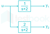
The block diagram of a system with one input u and two outputs y1 and y2 is given below.

A state space model of the above system in terms of the state vector x\underline x and the output vector 

\(\underline y = {\left[ {\begin{array}{*{20}{c}} {{y_1}}&{{y_2}} \end{array}} \right]^T}\)is

  1. ((a))

    \(\underline {\dot x} = \left[ 2 \right]\underline x + \left[ 1 \right]u;;;\underline y = \left[ {\begin{array}{*{20}{c}} 1&2 \end{array}} \right]\underline x\)

  2. ((b))

    \(\underline {\dot x} = \left[ { - 2} \right]\underline x + \left[ 1 \right]u;;;\underline y = \left[ {\begin{array}{*{20}{c}} 1\ 2 \end{array}} \right]\underline x\)

  3. ((c))

    \(\underline {\dot x} = \left[ {\begin{array}{{20}{c}} { - 2}&0\ 0&{ - 2} \end{array}} \right]\underline x + \left[ {\begin{array}{{20}{c}} 1\ 1 \end{array}} \right]u;;;\underline y = \left[ {\begin{array}{*{20}{c}} 1&2 \end{array}} \right]\underline x\)

  4. ((d))

    \(\underline {\dot x} = \left[ {\begin{array}{{20}{c}} 2&0\ 0&2 \end{array}} \right]\underline x + \left[ {\begin{array}{{20}{c}} 1\ 1 \end{array}} \right]u;;;\underline y = \left[ {\begin{array}{*{20}{c}} 1\ 2 \end{array}} \right]\underline x\)

Show Answer
Answer: ((b))

\(\underline {\dot x} = \left[ { - 2} \right]\underline x + \left[ 1 \right]u;;;\underline y = \left[ {\begin{array}{*{20}{c}} 1\ 2 \end{array}} \right]\underline x\)

x = yx˙=dy1dx\dot x = \frac{{d{y_1}}}{{dx}}

\(\underline y = \left[ {{y_2}} \right] = \left[ {\begin{array}{{20}{c}} 2\ {2x} \end{array}} \right] = \left[ {\begin{array}{{20}{c}} 1\ 2 \end{array}} \right]x\)

y1=1s+2u{y_1} = \frac{1}{{s + 2}}u

y˙1+2y1=u{\dot y_1} + 2{y_1} = u

x˙+2x=u\dot x + 2x = u

x˙+2x=u\dot x + 2x = u

x˙=[2]x+[1]u\underline {\dot x} = \left[ { - 2} \right]\underline x + \left[ 1 \right]u

Alternate solution 

Assume x be a state variable

[X(s)=1s+2u(s)][{\rm{X}}\left( {\rm{s}} \right) = \frac{1}{{s + 2}}u\left( s \right)]

sX(s)+2X(s) = U(S)

taking inverse laplace transform

x(t)’ + 2 x(t) = u(t)

x’(t)= u(t) – 2x(t)

output equation is given by

y1(t) = x

y2(t) = 2 x

50

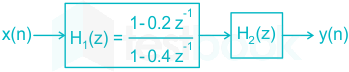
Two systems H1(z) and H2(z) are connected in cascade as shown below. The overall output y(n) is the same as the input x(n) with a one-unit delay. The transfer function of the second system H2(z) is

  1. ((a))

    10.4z1z1(10.2z1)\frac{{1 - 0.4{z^{ - 1}}}}{{{z^{ - 1}}\left( {1 - 0.2{z^{ - 1}}} \right)}}

  2. ((b))

    z1(10.4z1)(10.2z1)\frac{{{z^{ - 1}}\left( {1 - 0.4{z^{ - 1}}} \right)}}{{\left( {1 - 0.2{z^{ - 1}}} \right)}}

  3. ((c))

    z1(10.2z1)(10.4z1)\frac{{{z^{ - 1}}\left( {1 - 0.2{z^{ - 1}}} \right)}}{{\left( {1 - 0.4{z^{ - 1}}} \right)}}

  4. ((d))

    10.2z1z1(10.4z1)\frac{{1 - 0.2{z^{ - 1}}}}{{{z^{ - 1}}\left( {1 - 0.4{z^{ - 1}}} \right)}}

Show Answer
Answer: ((b))

z1(10.4z1)(10.2z1)\frac{{{z^{ - 1}}\left( {1 - 0.4{z^{ - 1}}} \right)}}{{\left( {1 - 0.2{z^{ - 1}}} \right)}}

The overall output y(n) is the same as the input x(n) with a one-unit delay.

y(n) = x(n - 1)

By applying z-transform,

Y(z) = z-1X(z)

H(z)=Y(z)X(z)=z1 \Rightarrow H\left( z \right) = \frac{{Y\left( z \right)}}{{X\left( z \right)}} = {z^{ - 1}} 

⇒ H1(z) H2(z) = z-1

(10.2z110.4z1)H2(z)=z1 \Rightarrow \left( {\frac{{1 - 0.2{z^{ - 1}}}}{{1 - 0.4{z^{ - 1}}}}} \right){H_2}\left( z \right) = {z^{ - 1}} 

H2(z)=z1(10.4z1)10.2z1\Rightarrow {H_2}\left( z \right) = \frac{{{z^{ - 1}}\left( {1 - 0.4{z^{ - 1}}} \right)}}{{1 - 0.2{z^{ - 1}}}}

51

An 8085 assembly language program is given below. Assume that the carry flag is initially unset. The content of the accumulator after the execution of the program is

MVI A, 07H

RLC

MOV B, A

RLC

RLC

ADD B

RRC

  1. ((a))

    8C H

  2. ((b))

    64 H

  3. ((c))

    23 H

  4. ((d))

    15 H

Show Answer
Answer: ((c))

23 H

MVI A, 07 H ⇒ 0000 0111 ← The content of 'A'

RLC ⇒ 0000 1110 ← The content of 'A'

MOVT B, A ⇒ 0000 1110 ← The content of 'B'

RLC ⇒ 0001 1100 ← The content of 'B'

RLC ⇒ 0011 1000 ← The content of 'B'

ADD B

\(\frac{A \space 0000 \space 1110\\

  • \
    B \space 0011 \space 1000}{0100 \space 0110}\)

RCC001020011323HRCC \rightarrow \frac{0010}{2}\frac{0011}{3} 23 H

52

The first six points of the 8 point DFT of a real-valued sequence are 5, 1 – 3j, 0, 3 – 4j, 0 and 3 + 4j. The last two points of the DFT will be respectively:

  1. ((a))

    0, 1 – 3;

  2. ((b))

    0, 1 + 3j

  3. ((c))

    1 + 3j, 5

  4. ((d))

    1 – 3j, 5

Show Answer
Answer: ((b))

0, 1 + 3j

Concept:

N-point DFT of a sequence x(n) defined for n = 0, 1, 2 ... N-1 is given by:

X(k)=n=0N1x(n)ejkωnX\left( k \right)=\sum_{n=0}^{N-1}x\left( n \right){{e}^{-jk\omega n}}

Also If x(n)DFTX(k)x(n)\overset{DFT}{\longleftrightarrow} X(k)

The Conjugate symmetric property of DFT states:

X(k) = X*(N – k) 'or' X(N – k) = X*(k) 

Calculation:

Given, X(k) = {5, 1 - 3j, 0, 3 – 4j, 0, 3 + 4j, A, B]

Where A and B are the missing variable values.

Using the conjugate symmetric property of DFT: X(k) = X*(N – k)

We find X(6) = A = X*(8 – 6) = X*(2)

With X(2) = 0, X*(2) = 0

So, X(6) = A = 0

Similarly,

B = X(7) = X*(8 – 7) = X*(1)

With, X(1) = 1 – 3j

X(7) = X*(1) = 1+3j

So, A = 0 and B = 1 + 3j

Option (2) is therefore correct.

53

For the BJT Q1 in the circuit shown below, β = ∞, VBEon = 0.7 V,  VCCEsat = 0.7 V. The switch is initially closed. At time t = 0, the switch is opened. The time t at which Q1 leaves the active region is

  1. ((a))

    10 ms

  2. ((b))

    25 ms

  3. ((c))

    50 ms

  4. ((d))

    100 ms

Show Answer
Answer: ((c))

50 ms

Apply KVL at input side, we get

 + 5 + 0.7 + 4.3 K(IE) – 10 = 0

IE = 1 mA ≃ IC    (∵ β = ∞)

Apply Nodal at output Node we get

  • 0.5 + 1 +ic = 0

Current through the  capacitor is , ic = - 0.5 mA

Also, VE(10)4.3k=1 mAVE=4.310=5.7 V\frac{{{V_E} - \left( { - 10} \right)}}{{4.3k}} = 1\ mA \to {V_E} = 4.3 - 10 = - 5.7\ V

Q1 leaves the active region means enters into saturation

∴ VCE(sat) = 0.7

VC – VE = 0.7

VC = 0.7 + VE = 0.7 – 5.7 = - 5 V

But iC=Cd(Vc0)dT{i_C} = C\frac{{d\left( {{V_c} - 0} \right)}}{{dT}}

\(\begin{array}{l} {V_C} = \frac{1}{C}\mathop \smallint \nolimits {i_c}.dt = \frac{{{i_C}}}{C}.\left( {{t_1}} \right)\ \left( { - 5} \right) = \frac{{\left( { - 0.5 \times {{10}^{ - 3}}} \right)}}{{5 \times {{10}^{ - 6}}}}{t_1}\ \therefore {t_1} = \frac{{25 \times {{10}^{ - 6}}}}{{5 \times {{10}^{ - 4}}}} = 5 \times {10^{ - 2}} = 50\ ms \end{array}\)

∴ Option (3) is correct

54

In the circuit shown below, network N is described by following Y-matrix:

\(Y = \left[ {\begin{array}{*{20}{c}} {0.1S}&{ - 0.01S}\ {0.01S}&{0.1S} \end{array}} \right]\).

Voltage gain V2V1\frac{{{V_2}}}{{{V_1}}} is:

  1. ((a))

    190\frac{1}{{90}}

  2. ((b))

    190- \frac{1}{{90}}

  3. ((c))

    199- \frac{1}{{99}}

  4. ((d))

    111- \frac{1}{{11}}

Show Answer
Answer: ((d))

111- \frac{1}{{11}}

Concept:

The Y-parameter equation for two-port network is given by:

I1 = Y11V1 + Y12V2

I2 = Y21V1 + Y22V2

Calculation:

Given Y11 = 0.1, Y12 = 0.01, Y21 = 0.01 and Y22 = 0.1

Putting the respective values in the standard equation, we get:

I1=0.1V10.01V2{I_1} = 0.1{V_1} - 0.01{V_2}   ---(1)

I2=0.01V1+0.1V2{I_2} = 0.01{V_1} + 0.1{V_2}   ---(2)

Applying KVL at the output loop we get:

V2=100I2{V_2} = - 100{I_2}

I2=1100V2I_2=-\frac{1}{100}V_2

Putting this in Equation (2), we get:

1100V2=0.01V1+0.1V2-\frac{1}{100}V_2=0.01V_1+0.1V_2

  • 0.01V2 = 0.01V1 + 0.1V2

0.11V2 = - 0.01V1

V2V1=111\frac{{{V_2}}}{{{V_1}}} = \frac{{ - 1}}{{11}}

55

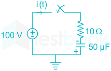
In the circuit shown below, the initial charge on the capacitor is 2.5 mC, with the voltage polarity as indicated. The switch is closed at time t = 0. The current i(t) at a time t after the switch is closed is 

  1. ((a))

    i(t) = 15 exp(-2 × 10³t)A

  2. ((b))

    i(t) = 5 exp(-2 × 10³t)A

  3. ((c))

    i(t) = 10 exp(-2 × 10³t)A

  4. ((d))

    i(t) = -5 exp(-2 × 10³t)A

Show Answer
Answer: ((a))

i(t) = 15 exp(-2 × 10³t)A

Q = 2.5 mC

Vinitial=2.5×10³C50×106FV_{initial} = \frac{2.5 × 10^{-3}C}{50 × 10^{-6}F}

Vinitial = 50 V 

Thus the net voltage = 100 + 50 = 150 V

The initial current at t = 0+ will be:

I = 150/10 = 15 A

The current at any time 't' will now be:

i(t)=15050i(t) = \frac{150}{50} exp(-2 × 10³t) A = 15 exp(-2 × 10³t)A

56

The system of equations

x + y + z = 6;

x + 4y + 6z = 20;

x + 4y + λz = μ

has NO solution for values of λ and μ given by

  1. ((a))

    λ = 6, μ = 20

  2. ((b))

    λ = 6, μ ≠ 20

  3. ((c))

    λ ≠ 6, μ = 20

  4. ((d))

    λ ≠ 6, μ ≠ 20

Show Answer
Answer: ((b))

λ = 6, μ ≠ 20

Concept:

The number of solutions can be determined by finding out the rank of the Augmented matrix and the rank of the Coefficient matrix.

  • If rank(Augmented matrix) = rank(Coefficient matrix) = no. of variables then no of solutions = 1.
  • If rank(Augmented matrix)  ≠ rank(Coefficient matrix) then no of solutions = 0.
  • If rank(Augmented matrix) = rank(Coefficient matrix) < no. of variables, no of solutions = infinite.


Calculation:

The augmented matrix for the system of equations is

\(\left[ {A{\rm{|}}B} \right] = \left[ {\left. {\begin{array}{{20}{c}} 1&1&1\ 1&4&6\ 1&4&\lambda \end{array}} \right|\begin{array}{{20}{c}} 6\ {20}\ \mu \end{array}} \right]\)

Performing: R3 → R3 – R2

\(\left[ {A{\rm{|}}B} \right] = \left[ {\left. {\begin{array}{{20}{c}} 1&1&1\ 1&4&6\ 0&0&{\lambda - 6} \end{array}} \right|\begin{array}{{20}{c}} 6\ {20}\ {\mu - 20} \end{array}} \right]\)      …

If λ = 6 and μ ≠ 20 then

Rank (A | B) = 3 and Rank (A) = 2

∵ Rank (A | B) ≠ Rank (A)

∴ Given the system of equations has no solution for λ = 6 and μ ≠ 20

57

A fair dice is tossed two times. The probability that the second toss results in a value that is higher than the first toss is

  1. ((a))

    2/36 

  2. ((b))

    2/6

  3. ((c))

    5/12 

  4. ((d))

    1/2

Show Answer
Answer: ((c))

5/12 

Total outcome are 36 out of which favourable outcomes are: (1, 2), (1, 3), (1, 4), (1, 5), (1, 6), (2, 3), (2, 4), (2, 5), (2, 6),(3, 4), (3, 5), (3, 6), (4, 5), (4, 6), (5, 6) which are 15.

Thus P(E)=No.;;of;favourable;outcomesNo.;;of;total;outcomes{\rm{P}}\left( {\rm{E}} \right) = \frac{{{\rm{No}}.{\rm{;;of;favourable;outcomes}}}}{{{\rm{No}}.{\rm{;;of;total;outcomes}}}}

P(E)=1536=512P(E)= \frac{{15}}{{36}} = \frac{5}{{12}}

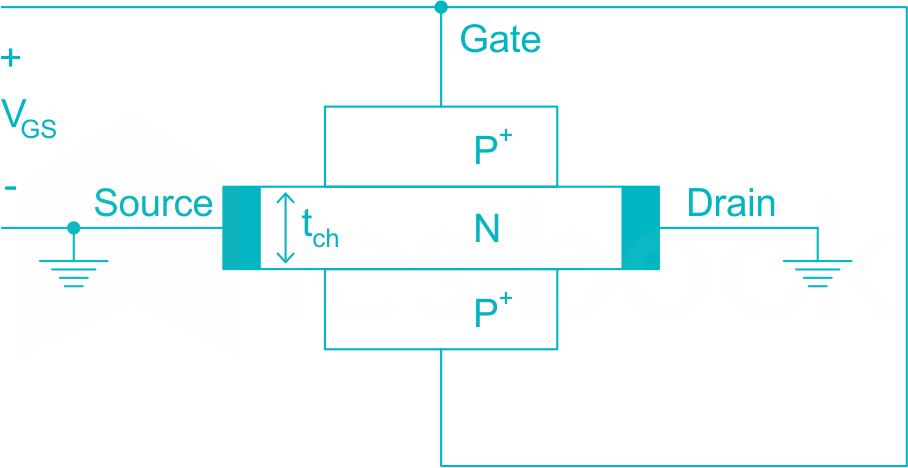
The channel resistance of an N-channel JFET shown in the figure below is 600 Ω when the full channel thickness (tch) of 10 μm is available for conduction. The built-in voltage of the gate P+ N junction (Vbi) is – 1 V. When the gate to source voltage (VGS) is 0 V, the channel is depleted by 1 μm on each side due to the built-in voltage and hence the thickness available for conduction is only 8 μm.

58

The channel resistance when VGS = -3 V is

  1. ((a))

    360 Ω

  2. ((b))

    917 Ω

  3. ((c))

    1000 Ω

  4. ((d))

    3000 Ω

Show Answer
Answer: ((c))

1000 Ω

1V built in potential deplete 1μm channel on each side. so, with an applied voltage of – 3V the width of the depletion region will be,

W2=W1Vbi+VRVbi=1μm[1+31]1/2=2μm{W_2} = {W_1}\sqrt {\frac{{{V_{bi}} + {V_R}}}{{{V_{bi}}}}} = 1\mu m{\left[ {\frac{{1 + 3}}{1}} \right]^{1/2}} = 2\mu m

So, with bias the effective channel width –

tch3=10μm2W2{t_{c{h_3}}} = 10\mu m - 2{W_2}( = 10\mu m - 2 \times 2=6\mu m\)

∴Channel resistance, rd3=rd1(tch1tch3){r_{{d_3}}} = {r_{{d_1}}}\left( {\frac{{{t_{c{h_1}}}}}{{{t_{c{h_3}}}}}} \right)( = 600\frac{{10\mu m}}{{6\mu m}}= 1000\ Ω\)

59

The channel resistance when VGS = 0 V is

  1. ((a))

    480 Ω

  2. ((b))

    600 Ω

  3. ((c))

    750 Ω

  4. ((d))

    1000 Ω

Show Answer
Answer: ((c))

750 Ω

Resistance of the FET with respect with respect to channel thickness is given by

rd1tch{r_d} \propto \frac{1}{{{t_{ch}}}}

rd1rd2=tch2tch1\therefore \frac{{{r_{{d_1}}}}}{{{r_{{d_2}}}}} = \frac{{{t_{c{h_2}}}}}{{{t_{c{h_1}}}}}

or, 600Ωrd2=810=750Ω\frac{{600{\rm{\Omega }}}}{{{{\rm{r}}_{{{\rm{d}}_2}}}}} = \frac{{8}}{10} = 750{\rm{\Omega }}

60

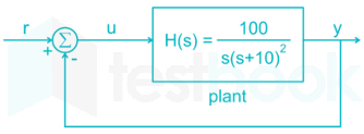
The input-output transfer function of a plant  H(s)=100s(s+10)2;.H\left( s \right) = \frac{{100}}{{s{{\left( {s + 10} \right)}^2}}};.The plant is placed in a unity negative feedback configuration as shown in the figure below.

The gain margin of the system under closed loop unity negative feedback is

  1. ((a))

    0 dB

  2. ((b))

    20 dB

  3. ((c))

    26 dB

  4. ((d))

    46 dB

Show Answer
Answer: ((c))

26 dB

For determining phase cross over frequency ∠G(jω)H(jω) = - 180°

G(s)H(s)=100s(s+10)2G\left( s \right)H\left( s \right) = \frac{{100}}{{s{{\left( {s + 10} \right)}^2}}}

G(s)H(s)=902tan1(ωp10)=180 \Rightarrow \angle G\left( s \right)H\left( s \right) = - 90^\circ - 2{\tan ^{ - 1}}\left( {\frac{{{\omega _p}}}{{10}}} \right) = - 180^\circ

tan1(ωp10)=45{\tan ^{ - 1}}\left( {\frac{{{\omega _p}}}{{10}}} \right) = 45^\circ

ωp=10;rad/s{\omega _p} = 10;rad/s

GM=20log10G(jωp)H(jωp)GM = - 20{\log _{10}}\left| {G\left( {j{\omega _p}} \right)H\left( {j{\omega _p}} \right)} \right|

=20log10(10010(102+100))=20log10(120)=26;dB= - 20{\log _{10}}\left( {\frac{{100}}{{10\left( {{{10}^2} + 100} \right)}}} \right) = - 20{\log _{10}}\left( {\frac{1}{{20}}} \right) = 26;dB

61

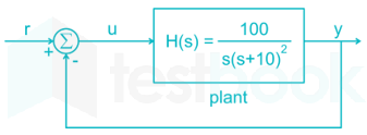
The input-output transfer of a plant H(s)=100s(s+10)2;.H\left( s \right) = \frac{{100}}{{s{{\left( {s + 10} \right)}^2}}};.The plant is placed in a unity negative feedback configuration as shown in the figure below.

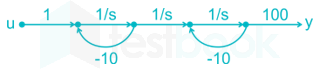
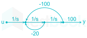
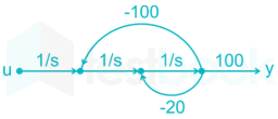
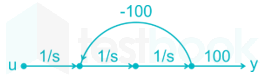
The signal flow graph that DOES NOT model the plant transfer function  H(s)=100s(s+10)2H(s) = \frac{{100}}{{s{{\left( {s + 10} \right)}^2}}} is:

1. 

2. 

3. 

4. 

  1. ((a))

    1 and 2

  2. ((b))

    4

  3. ((c))

    2 and 3

  4. ((d))

    2 and 4

Show Answer
Answer: ((b))

4

Let us go by SFG one by one, 

1:

Forward paths: 100/s3

Loops: -10/s, -10/s

Non touching loops: -10/s × -10/s

Transfer function = 100s31+100s2+20s\frac{\frac{100}{s^3}}{1+\frac{100}{s^2}+\frac{20}{s}}

=100s3s2+100+20ss2=100s(s+10)2= \frac{\frac{100}{s^3}}{\frac{s^2+100+20s}{s^2}} = \frac{100}{s(s+10)^2}

2:

Forward path: 100/s3

Loops: -20/s, -100/s2

Transfer function = 100s31+100s2+20s\frac{\frac{100}{s^3}}{1+\frac{100}{s^2}+\frac{20}{s}}

=100s3s2+100+20ss2=100s(s+10)2= \frac{\frac{100}{s^3}}{\frac{s^2+100+20s}{s^2}} = \frac{100}{s(s+10)^2}

2 and 3 are very similar. 

4:

Forward paths: 100/s3

Loops: -100/s2

Transfer function = 100s31+100s2\frac{\frac{100}{s^3}}{1+\frac{100}{s^2}}

=100s3s2+100s2=100s(s2+100)= \frac{\frac{100}{s^3}}{\frac{s^2+100}{s^2}} = \frac{100}{s(s^2+100)}

T.F=H(s)=100s(s2+100)100s(s+10)2T.F = H\left( s \right) = \frac{{100}}{{s\left( {{s^2} + 100} \right)}} \ne \frac{{100}}{{s{{\left( {s + 10} \right)}^2}}}

4 does not represent the given transfer function.

62

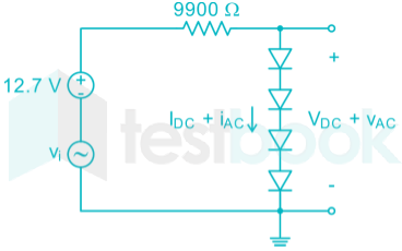
In the circuit shown below, assume that the voltage drop across a forward biased diode is 0.7 V. The thermal voltage Vt = KT/q = 25 mV. The small signal input Vi = VPcos (ωt) where

VP = 100 mV

The bias current IDC through the diodes is

  1. ((a))

    1 mA

  2. ((b))

    1.28 mA

  3. ((c))

    1.5 mA

  4. ((d))

    2 mA

Show Answer
Answer: ((a))

1 mA

Apply DC analysis    → Diode acts as a voltage source of 0.7 V

idc=12.74(0.7)9900=1 mA\therefore {i_{dc}} = \frac{{12.7 - 4\left( {0.7} \right)}}{{9900}} = 1\ mA

∴ Option (1) is correct

63

In the circuit shown below, assume that the voltage drop across a forward biased diode is 0.7 V. The thermal voltage VTV_T = KT/q = 25 mV. The small signal input ViV_i = VPV_Pcos (ωt) where

VPV_P = 100 mV


The ac output voltage Vac  is

  1. ((a))

    0.25 cos(ωt) mV

  2. ((b))

    1 cos (ωt) mV

  3. ((c))

    2 cos (ωt) mV

  4. ((d))

    0.22 cos (ωt) mV

Show Answer
Answer: ((b))

1 cos (ωt) mV

In DC analysis 

Idc=12.74(0.7)9900=1;mA{I_{dc}} = \frac{{12.7 - 4\left( {0.7} \right)}}{{9900}} = 1;mA

In AC analysis Diode acts like a resistor whose value is

rac=ηVTIdc=25mV1mA=25Ω{r_{ac}} = \frac{{\eta {V_T}}}{{{I_{dc}}}} = \frac{{25mV}}{{1mA}} = 25{\rm{\Omega }}


VAC=VPcos t×(25+25+25+25)9900+4(25)=100cosωt×100×10310000=1 cosωt mV\therefore {V_{AC}} = \frac{{{V_P}cos\ t \times \left( {25 + 25 + 25 + 25} \right)}}{{9900 + 4\left( {25} \right)}} = \frac{{100cos\omega t \times 100 \times {{10}^{ - 3}}}}{{10000}} = 1\ cos\omega t\ mV

∴ option (2) is correct

64

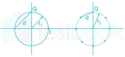
A four phase and an eight phase signal constellation are shown in figure

For the constraint that the minimum distance between  pairs of signal points be d for both constellation the radii r1\rm r_1 and r2\rm r_2 of the circle are

  1. ((a))

    r1 = 0.707 d, r2 = 2.782 d

  2. ((b))

    r1 = 0.707d, r2 = 1.932d

  3. ((c))

    r1 = 0.707 d, r2 = 1.54 d

  4. ((d))

    r1 = 0.707 d, r2 = 1.307 d

Show Answer
Answer: ((d))

r1 = 0.707 d, r2 = 1.307 d

\(\rm \eqalign{ & \rm r_1^2 + r_1^2 = {d^2} \cr & \rm 2r_1^2 = {d^2} \cr & \rm {r_1} = \frac{d}{{\sqrt 2 }} = 0.707;d \cr} \)

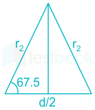
For constellation 2, two radii lines from the center to two consecutive points and the line between them form an isosceles triangle as shown below

\(\eqalign{ & \rm \cos 67.5 = \frac{{d/2}}{{{r_2}}} \cr & \rm {r_2} = 1.307d \cr} \)

65

Assuming high SNR and that all signals are equally probable, the additional average transmitted signal energy required by 8-ary PSK signal to achieve the same error probability as the 4-ary PSK is

  1. ((a))

    11.90 dB\rm 11.90\ dB

  2. ((b))

    8.73 dB\rm 8.73 \ dB

  3. ((c))

    6.79 dB\rm 6.79 \ dB

  4. ((d))

    5.33 dB\rm 5.33 \ dB

Show Answer
Answer: ((d))

5.33 dB\rm 5.33 \ dB

Probability of error In M- PSK is given by 

Pe=2erfc2EsN0sin2πM{P_e} = 2erfc\sqrt {\frac{{2{E_s}}}{{{N_0}}}{{\sin }^2}\frac{\pi }{M}}

M = 4 for 4 ary  PSK 

, =8 for 8 PSK

Pe;4PSK=2erfc2Es;4PSKN0sin2π4{P_{e;4PSK}} = 2erfc\sqrt {\frac{{2{E_{s;4PSK}}}}{{{N_0}}}{{\sin }^2}\frac{\pi }{4}}

Pe;8PSK=2erfc2Es;8PSKN0sin2π8{P_{e;8PSK}} = 2erfc\sqrt {\frac{{2{E_{s;8PSK}}}}{{{N_0}}}{{\sin }^2}\frac{\pi }{8}}

Equating the two equations

ES8PSKES4PSK=(sinπ4sinπ8)2\frac{{{E_{S8PSK}}}}{{{E_{S4PSK}}}} = {\left( {\frac{{\sin \frac{\pi }{4}}}{{\sin \frac{\pi }{8}}}} \right)^2} = 3.414

E 8PSK db - E 4 PSK db = 10 Log( 3.414) = 5.33 dB

Attempt this paper under real exam conditions

Timed interface, section switching, instant scoring, and question-by-question analytics — free.

Start Timed Attempt